
Performance Enhancement of MIMO-OFDM Using Redundant Residue Number System
Volume 3, Issue 4, Page No 01-07, 2018
Author’s Name: Mohamed Abd Elghany Khalifaa), Amr Elsayed Emam, Mohamed Ibrahim Youssef
View Affiliations
Al-Azhar university, Electrical Engineering Department, Faculty of Engineering, Cairo, Egypt
a)Author to whom correspondence should be addressed. E-mail: mohamedgheth@yahoo.com
Adv. Sci. Technol. Eng. Syst. J. 3(4), 01-07 (2018); ![]() DOI: 10.25046/aj030401
DOI: 10.25046/aj030401
Keywords: Conventional Codes, Equalizers, Error Detection and Correction, Redundant Residue Number System, Wireless Communication.

Export Citations
The data transmitted over wireless communication systems are affected by various elements as noise, interference or distortion, and to be able to combat these factors the paper propose the utilization of Redundant Residue Number System (RR NS) coding as a Forward Error Correction (FEC) technique to enhance the performance of MIMO-OFDM communication system compared to other conventional coding and equalization techniques.
The system Bit Error Rate (BER) and Peak-to-Average Power Ratio (PAPR) were measured through a MATLAB programs for different simulated channel conditions, including the effect of signal amplitude reduction and multipath delay spreading. The simulation results had shown that RRNS coding scheme provides an enhancement BER performance and reduced PAPR in comparison to conventional error detection and correction schemes through using the distinct features of Residue Number System (RNS).
Received: 24 May 2018, Accepted: 27 June 2018, Published Online: 02 July 2018
1. Introduction
The wireless communication systems defined in IEEE standards (802.11n WLAN and 802.16 WMAN), are based on Multiple-Input-Multiple-Output (MIMO) antenna along with Orthogonal Frequency Division Multiplexing (OFDM) technology, which are referred to as MIMO-OFDM system.
The MIMO-OFDM system, provide an attractive wireless communication system that fits future wireless networks through providing high-data-rate wireless access at high Quality of Service (QoS) taking into accounts that the spectrum is a rare resource element and propagation conditions are difficult due to existence of fading and interference from other signals. [1]
The MIMO antenna technology from its side provides efficient frequency spectrum usage through spatial multiplexing gain, and enhanced communication link reliability because of the transmit system diversity gain [2]. On the other hand, the OFDM block distribute data over multiple numbers of closely spaced orthogonal carriers providing higher spectral efficiency by spacing the channels closer together without fearing from harmful effect of inter-carrier interference as carriers are orthogonal to each other.
Still, the wireless digital networks are prone to bit errors during transmission, thus error detection and correction techniques are implemented to reduce bit-error effects and ensure receiver eventually is able to restore the correct packet of information.
A new coding scheme for error detection and correction in MIMO-OFDM communication systems is provided in the paper using a Redundant Residue Number System (RRNS) instead of the current error control codes, where the RRNS had showed an enhanced system performance over conventional error correction techniques.
The paper starts with a short description on the Forward Error Correction (FEC) Methodology as seen in section 2, then in section 3 the Residue Number System and redundancy features and applications are given, followed in section 4 by illustration for RRNS error detection and correction implementation. In section 5, the overall system architecture is provided, and in section 6 methods of system evaluation are given. In section 7 simulation results are provided for the analysis of the communication system performance and finally in section 8 a conclusion was drawn.
2. Forward Error Correction Methodology
The Forward Error Corrections are methods which are used to enhance the channel capacity through adding redundant data to the message in a way that it can be restored at the receiving side even if there are a errors present during the transmission process. This redundant data allow receiver to detect and correct errors without needing to retransmit the message again and without requiring a handshaking process between Transmit/Receive systems. [3]
The advantage of FEC schemes is shown in noisy channels where a large number of retransmissions would be required – in case of its absence – before a packet is received free of errors. Also, it is used in cases where no feedback exists between the receiver and the transmitter.
The encoded message could be systematic coded if portion of the output is directly resembling the input or non-systematic coded if the output is a modified form of the original information through shuffling original message symbols across several code using an inter-leaver to improve the performance of FEC codes, and thus the errors would have a more uniform distribution form.[4]
The coding techniques used as FEC schemes in previous literature [5, 6], could be categorized as block error correction codes, and convolutional error correction codes. The first ones are as Hamming, BCH, Reed-Solomon, and turbo codes, while the second ones are as Viterbi, and Low-Density Parity Check Code (LDPC).
3. Residue Number System Review
The RNS provides an efficient and effective arithmetic computation through transformation of large integers into smaller sets of digits.
The Residue numbers has unique features, as it is a carry-free arithmetic, which implies its ability to perform the operations related to the individual residue digits of different moduli independently. Also, the residue representations carry no weight-information which prevents the propagation of error in other digit-positions [7].
The RNS defined through selecting v positive pair-wise relative primes mi (i = 1, 2, 3 … v) referred to as moduli, such that any integer N, describing a message, is given by the sequence (r1, r2 ..rv) in the range 0<N<MI in a unique matter;
![]() Where;
Where;
ri is remainder that is least positive when N is divided by modulus mi
![]() Where;
Where;
MI is the dynamic range of information symbols’.
Then; to restore the symbols, two approaches are available; a parallel implementation scheme through using the Chinese Reminder Theorem (CRT) or a sequential approach that use the Mixed Radix Conversion (MRC) algorithm. In the coming subsection a description of the two methods are provided.
3.1. Chinese Remainder Theorem Method
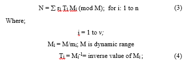
The method relies on a mathematical idea that was given in the 4th century AD in china [8 – 10]; where for any v-tuple (r1, r2 ….rv) such that 0≤ri<mi; there is only one integer N where 0 ≤ N < Mi and ri = N (mod mi) which allows to recover the message. The numerical value of N is calculated based on equation (3):
3.2. Mixed Radix Conversion Method
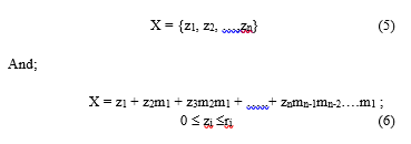
For a of pair-wise relatively prime moduli set {m1, m2, ….,mn} and a residue state {r1, r2, ….rn} of a number X, that number can be uniquely represented in mixed-radix form as given in equation (5) and (6): [11]
 So, all what is required is to obtain the value of zi to determine X. Where each value of z is represented as function of the moduli and residue representations as seen in table (1);
Table (1): Representation of zi
| Parameter | Representation |
| z1 | = r1 |
| z2 | = ||m1-1|m2 (r2-z1)|m2 |
| z3 | = ||(m2m1)-1|m3 (r3 – (z2m1 + z1)|m3 |
| zn | = ||( mn……m2m1)-1|mn (rn – rn-1 mn-2 ….. z2m1 + z1)|mn |
And as seen in table (1), the Mixed Radix Conversion (MRC) is considered a sequential process, where obtaining zi requires generating zi-1 first.
4. Proposed Error Detection and Correction Algorithm
The provided error detection and correction scheme use a set of RNS moduli’s as an information symbols and additional RNS moduli’s as a redundant symbol, all are which addressed as Redundant Residue Number System (RRNS). Through the use of RRNS it gives the designer, advantages both in terms of error detection and correction capabilities and in terms of maximum operating frequency. In fact, the operations on each residue digit are independent and so the mathematical operations as addition, subtraction, and multiplication on the full dynamic range are split in various channels and executed in a parallel way on each of the moduli over a smaller dynamic range.
In this scheme the redundant moduli’s’ are selected to be greater than any of the other chosen moduli set and are not used in determining the dynamic range of the system. So, the RRNS is obtained by inserting an additional (u − v) number of moduli mv+1;mv+2; …..;mu, where mv+j ³ max{m1;m2; ……;mv} as a redundant modulus, to the previously introduced RNS, to form an RRNS of u positive, pairwise relative prime moduli. [12, 13]
So, an integer N in the range [0;MI] is represented as a u-tuple residue sequence, (r1; r2; …….; ru) with respect to the u moduli. The properties of the RNS indicated in the previous section; especially the independence of digits allows recovering the integer N by any v out of u residue digits using their related moduli, which would enable the redundant residue number to be used for self-checking, error-detection and correction in digital processors as seen in Figure (1). In addition, the RRNS technique is the only one that is capable of using the same arithmetic module for generating both the original information part and the parity part of a RRNS code-word [7].
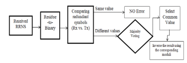 Figure 1. Error detection and correction algorithm
From Figure (1) seen above; the received redundant symbols are converted back to binary system and compared to the expected ones, and through this comparison the system would detect the occurrence of an error in the transmitted message.
Then, for error correction it is required to identify the modulus that generated the error either in m3, or m2 or m1. Using the MRC method [11], a test on each of the information moduli with the two redundant moduli is performed and through this test it was able to identify and correct the bit which generated the error [14]. Thus, through the detection and correction algorithm, the error would be detected and corrected without the need to re-transmit again the information.
5. System Model
The communication system, as shown in Figure (2) is initialized with a binary data random source, that is converted to residue numbers and protected from errors by adding parity residue symbols using the RRNS encoding algorithm provided in section 4 instead of using LDPC encoder currently used in DVB-S2 communication systems, then the packet is modulated, coded through the Space-Time Block Coding (STBC) encoder that configure the way information are routed on multiple antenna system using algorithms as alamouti scheme [15], passed to a Serial-To-Parallel (S/P) converter for parallel transmission and then through an Inverse Fast Fourier Transform (IFFT) block where both act as an OFDM transmitter, and again converted back to serial sequence through Parallel-To-Serial (P/S) converter to the transmission antenna array system.
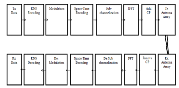 Figure 2. MIMO-OFDM System model
Before transmission a Cyclic prefix (CP) is inserted to combat the effect of Inter Symbol Interference (ISI) and Inter Carrier Interference (ICI) that would be caused by the multipath channel [16]. This CP is an image of the last section of the OFDM symbol that is inserted in the front of transmitted OFDM symbol.
To represent the satellite channel in the model shown in Figure (2), several channel fading are given; starting with Additive White Gaussian Noise (AWGN) channel, and then adding multipath fading factors through using Rice-Log-Normal distribution (RLN) distribution fading model [17].
The receiver blocks are the reverse blocks of the transmitter; where the CP is removed from the received stream, Serial-To-Parallel (S/P) converter for parallel transformation then passed to a Fast Fourier Transform (FFT) that is used to demodulate the signals for each residue sub-channel, and then converted back again to serial sequence through Parallel-To-Serial (P/S) converter. Then, the signal is decoded using the STBC, demodulated and recovered after R/B (Residue-to-Binary conversion).
6. Evaluation Methods
The RRNS-based MIMO-OFDM system performance is evaluated through the parameters defined and presented in this section.
6.1. Bit Error Rate (BER) measurements
The error probability for M-PSK modulated transmission in AWGN is given by:
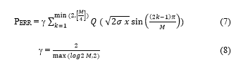 Where;
M is the constellation size,
r is the SNR per symbol.
x is a chi-square distributed random variable.
6.2. PAPR Evaluation Method
The performance is evaluated by measuring the Peak-to-Average Power Ratio (PAPR) of the signal x(t) [18], as seen in equation (9);
![]() Where;
Where;
E = Expectation operator
6.3. Channel Capacity
A way to characterize the channel performance of the system is through the Shannon channel capacity metric. Shannon in [19] defined the capacity as the maximum information rate a channel can support at a low error probability. The capacity of MIMO system is given in equation (10) as;
![]() Where;
Where;
In : n × n identity matrix
N: The number of transmit antennas
HH: Conjugate transpose of H
7. Simulation Results
The proposed system performance was investigated using MATLAB tool, which involves the transmission of data streams through a FEC coding scheme whose integrity depends on OFDM with 512-ary QAM and Cyclic Prefix (CP):1/8, over different fading channels.
The examination was focused on the utilization of either equalizers or coding schemes as an error correction techniques, and analyzing the system performance of such techniques with that using RNS with redundant moduli’s as an error detection and correction algorithm.
The MIMO-OFDM system performance was studied through measuring the BER and PAPR over AWGN, Rayleigh and Rician Lognormal (RLN) fading channel conditions.
7.1. Using Equalizers as Error correction scheme
The BER performance as seen in Figure (3), takes into account the simulation of several types of equalizers that are utilized for error correction.
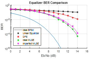 Figure 3. BER w.r.t Eb/No for various Equalization techniques
From figure (3), it is seen the enhanced performance of MLSE over DFE and linear equalizer, and thus next simulations focus on analyzing the performance of MIMO-OFDM with RNS coding system with and without MLSE equalizer over the RLN + AWGN channel, as seen in Figure (4).
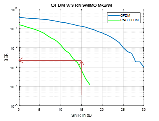 Figure 4.a. MIMO-OFDM RNS system with Equalizer
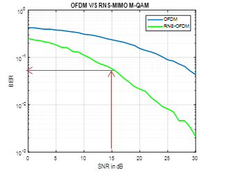 Figure 4.b. MIMO-OFDM RNS system without Equalizer
From Figure (4), for a SNR = 15, the BER for the communication system with error correction is 1*10-3 while it reaches 5*10-2 for the system without error correction.
7.2. BER performance with Current Coding Correction Schemes
The performance over AWGN channels for current error correction schemes that utilize coding approach as seen in Figure (5), shows that Golay code (which is a Block Error correction type) provides the best error correction code compared to other cods.
The current generation of linear block codes uses LDPC coders which utilize high multiplexing capacity and are differentiated from Golay codes through decoding approach; whereas binary Golay codes are decoded through algebraic methods, the LDPC codes are decoded in an iterative approach. In the next subsections analysis will be focused on LDPC coders as it is the one that is currently used in DVB-S2 systems.
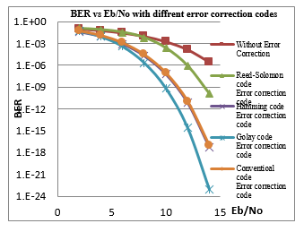 Figure 5. BER vs. Eb/No for current correction codes
7.3. Using Coding Techniques as Error correction scheme
Implementing an MIMO-OFDM communication system and comparing the system when converting the transmitted bits to residue coding (RNS-OFDM), and again when using LDPC algorithm as FEC Scheme (FEC-RNS-OFDM).
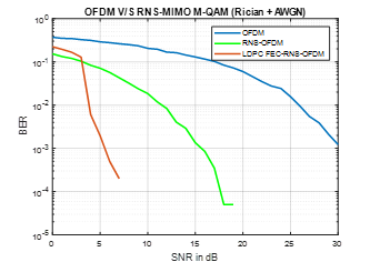 Figure 6.a. MIMO-OFDM RNS system with FEC coding (Rician Channel)
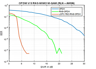 Figure 6.b. MIMO-OFDM RNS system with FEC coding (RLN Channel)
Where; Figure (6.a) and (6.b) shows the performance, enhancement done going from OFDM to RNS-OFDM then implementing an FEC-LDPC scheme. Also, the effect over different channels (small and deep fading) has been analyzed.
7.4. Comparison between different Error correction techniques
After analyzing in previous subsections, the utilization of equalizers and coding techniques as an error correction schemes; both techniques are compared over RLN + AWGN channel as seen in Figure (7).
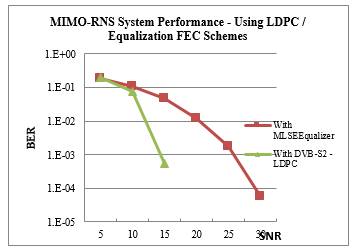 Figure 7. MIMO-OFDM RNS system with FEC schemes
In Figure (7) above, the LDPC coding provide enhanced performance over MLSE equalizer as an error correction scheme especially for higher SNR.
7.5. BER Performance for RRNS as FEC scheme
The system performance is evaluated with respect to the proposed scheme that utilize RNS coding with redundant moduli’s for MIMO-OFDM system as an alternative error correction method. A redundant error correction using RNS is used were RNS moduli’s are {3, 5, 7}, and redundant set is {11}.
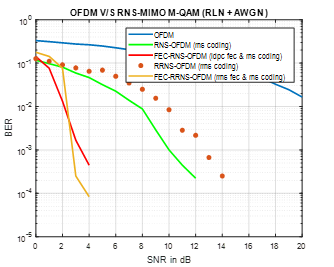 Figure 8. MIMO-OFDM system performance
From Fig (8) seen above, the error correction scheme with redundant RNS provide a comparable performance with that using LDPC scheme that is currently used in DVB-S2 systems.
7.6. BER for RNS vs. RRNS schemes in MIMO-OFDM System
Using RNS moduli’s {3, 5, 7, 11}, and redundant set initially with moduli {13} then with redundant moduli’s {13, 17}, evaluating the system performance with and without redundant moduli’s as seen in Figure (9).
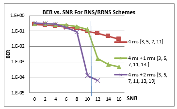 Figure 9. RRNS vs. RNS Performance comparison
From the above Figure (9), it is shown that for a SNR = 11db, an enhancement of the BER by 1 dB is seen when using one redundant moduli, and 3 dB when using two redundant moduli’s in-comparison to the system without redundant moduli’s.
7.7. PAPR performance for MIMO-OFDM with RRNS as FEC
For a MIMO-OFDM system over an ITU LOS + AWGN fading model channel, the PAPR for the transmitted signal is as shown in Figure (10).
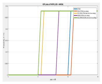 Figure 10. PAPR measurement for MIMO-OFDM system
From the above Figure (10), it is shown that the system with RRNS has the minimum signal amplitude by about 20% compared with LDPC FEC scheme (FEC-RNS-OFDM) and better than the systems that don’t use FEC schemes.
7.8. Effect of Increasing RNS moduli on channel capacity
In Figure (11) a MIMO-OFDM system is analyzed over a RLN + AWGN channel for various RNS moduli sets.
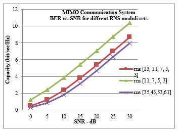 Figure 11. Channel Capacity for various RNS moduli sets
Where, in Figure (11) it is shown that the increase of number of RNS moduli value leads to a decrease in channel capacity due to the increased amplitude representation, and thus it is better to select some low order moduli set to be able to enhance the system performance.
8. Conclusion
The usage of RNS coding with its ability for parallel distributed arithmetic and independence between different arithmetic blocks, would simplify the overall system design and reduces the complexity of the individual building blocks.
The paper provides a method to detect and correct signal errors using RRNS. Where a four and then a six-length moduli set have been proposed; in the first time three out of the four were information moduli and one was redundant moduli, and in the second the first four moduli set is the information moduli and the last two is the redundant moduli respectively. Thus, a one and again two redundant moduli were used for error detection and correction.
Through the performed simulations it was proven that this system provide less receiving system complexity and the straight forward error detection algorithm due to the absence of carry propagation between the arithmetic blocks, reduced dynamic power by about 20% due to using small arithmetic units, and finally enhanced error detection and correction features, which improves as the redundant moduli increase taking benefit from the independent transmission feature; where an error in one sub-channel in RNS is not propagated into the other sub-channels and thus isolating the faulty residuals and as a consequence allow for fault tolerance and facilitate error detection and correction, but on the other hand this comes on the expense of reducing the available communication system channel capacity.
Conflict of Interest
I would like to declare that there is no conflict of interest.
- H. Bolcskei, “MIMO-OFDM wireless systems: basics, perspectives, and challenges,” in IEEE Wireless Communications, vol. 13, no. 4, pp. 31-37, Aug. 2006. doi: 10.1109/MWC.2006.1678163
- A. J. Paulraj, R. U. Nabar, and D. A. Gore, Introduction to Space-Time Wireless Communications, Cambridge, UK: Cambridge Univ. Press, 2003.
- Jatinder Singh, Jaget Singh. “A Comparative study of Error Detection And Correction Coding Techniques”, 2012 Second International Conference on Advanced Computing & Communication Technologies.
- B. Vucetic; J. Yuan (2000). Turbo codes: principles and applications. Springer Verlag. ISBN 978-0-7923-7868-6.
- DVB-S. EN 300 421 V1.1.2 (08/97). Digital Video Broadcasting; Framing structure, channel coding and modulation for 11/12 GHz satellite services. ETSI, 1997.
- DVB-S2. EN 302 307 V1.1.2 (06/06). Digital Video Broadcasting; Second generation framing structure, channel coding and modulation systems for Broadcasting, Interactive Services, News Gathering and other broadband satellite applications. ETS, 2006.
- M. Roshanzadeh, A. Ghaffari and S. Saqaeeyan, Using Residue Number Systems for Improving QoS and Error Detection & Correction in Wireless Sensor Networks, Communication Software and Networks (ICCSN), May 2011 IEEE 3rd International Conference on Page: 1-5
- K. W. Watson, “Self-checking computations using residue arithmetic,” Proc. IEEE, vol. 54, pp. 1920–1931, Dec. 1966.
- Hao-Yung Lo, Ting-Wei Lin, 2013. “Parallel Algorithms for Residue Scaling and Error Correction in Residue Arithmetic”. published by Wireless Engineering and Technology, Vol.4 No.4.
- A. Omondi, Residue number systems: theory and implementation. Imperial College Press, 2007.
- Pallab Maji, June 2011. Application of Residue Arithmetic in Communication and Signal Processing. Master of Science. NATIONAL INSTITUTE OF TECHNOLOGY, Rourkela, Orissa-769008, India
- Aingel James, Ameenudeen Pe, Jilu James, Minny George, “Multiple error correction using non-binary Redundant Residue Number System”, India Conference (INDICON) 2015, 2015, ISSN 2325-9418.
- Hari Krisna, Kuo-Yu Lin, and Jenn-Dong Sun, A coding Theory Approach to Error Control in Redundant Residue Number Systems- Part I: Theory and Single Error Correction, IEEE Transactions on Circuits and Systems II: Analog and Digital Signal Processing Vol 39 issue 1 pp 8-17 Jan 1992
- Salifu Abdul-Mumin1, Kazeem Alagbe Gbolagade, “An Improved Redundant Residue Number System Based Error Detection and Correction Scheme for the Moduli Set”. Advances in Wireless Communications and Networks journal, 2016; 2(1): 11-14.
- Devlal, Y. (2015). MIMO Performance analysis with Alamouti STBC Code and V-BLAST Detection Scheme. International Journal of Science, Engineering and Technology Research (IJSETR), 4(1), 199-204. Retrieved from ijsetr.org/wp-content/uploads/2015/01/IJSETR-VOL-4-ISSUE-1-199-204.pdf.
- Sandeep Kaur, Gurpreet Bharti, “Orthogonal Frequency Division Multiplexing in Wireless Communication Systems: A Review”. International Journal of Advanced Research in Computer Engineering & Technology Vol. 1, Issue 3, May 2012
- Vatalaro, Francesco & Mazzenga, F & De Maio, G & Forcella, A. (2002). The generalized Rice lognormal channel model—first and second order statistical characterization and simulation. International Journal of Satellite Communications. 20. 29 – 45. 10.1002/sat.700.
- Paredes, M. (2015). Reduction of peak-to-average power ratio in OFDM systems. doi:10.14711/thesis-b650985
- Ramoni Adeogun, “Capacity and Error Rate Analysis of MIMO Satellite Communication Systems in Fading Scenarios”, International Journal of Electrical and Computer Engineering (IJECE) Vol. 4, August 2014.