Effects of Dielectric Properties of the Material located inside Multimode Applicator on Microwave Efficiency

Adv. Sci. Technol. Eng. Syst. J. 3(3), 61–66 (2018);
 DOI: 10.25046/aj030309
During microwave heating of materials, the efficiency of microwave heating depends on the materials’ dielectric property, shapes and sizes of the material, materials’ position inside the applicator, operating frequency, level of input power, specific heat capacity, number and position of waveguide over the applicator, size and geometry of applicator etc. This paper examines the effects of dielectric properties of the clay sample placed in the multimode applicator on the performance of microwave heating. The simulated and experimentally obtained results show that the variation in clay samples dielectric value creates variation in system efficiency inside the microwave applicator. Also placing another dielectric slab over the material to be heated affects the electric field distribution and system efficiency. Placing KESTAMID dielectric slab over the material improved the heating efficiency by 22%. COMSOL Multiphysics software was used to simulate and estimate the electric field distribution over the surface of the clay sample and inside the multimode applicator for different dielectric property clay samples. The simulated and experimentally obtained results are almost matched.
1. Introduction
In recent days, microwave heating is gaining popularity as an alternative heating technique in many industries due to its high heating rates, significant energy saving, reduced processing time, selective and volumetric heating. Also microwave applications involve environmental friendly usage, safer handling and improved quality of materials etc [1,2]. Due to its various advantages, microwave has found applications in the drying of foods [3], drying of textiles[4], drying of zinc sulfate [5], recycling of polymeric materials [6], coal mining [7], vulcanizations of rubber[8,9], drying and sintering of ceramics [10], and drying of bagasse [11]. However, low heating efficiency is a limitation for microwave heating applications in practice.
High heating efficiency is one of the most desired characteristics for both industrial and domestic microwave ovens since electric energy is expensive and because low efficiencies indicate high power reflections, which might damage the magnetron. Also the quality of the processed material is determined by its heating efficiency. So far microwave heating efficiency is improved by matching the load through different methods like using external devices, such as tuners, stubs or irises, feeding the applicator from more than one position [12], covering the sample material with dielectric multilayer [13] or by changing the position of the sample material inside multimode applicator [14]. However, the above mentioned techniques have their own limitation and difficulties in the overall cost of the system.
In microwave heating process, a number of factors are responsible for electric field distribution inside multimode microwave applicator. Among them samples’ location, dielectric property, sample size and shape, applicators’ size and its geometry, incident power and operating frequency are most important. In recent years, the effects of size, shape, applied power, operating frequency, samples’ location and dielectric properties have been studied both experimentally and numerically on microwave heating efficiency and it was found out that for each different sample, varied efficiency is obtained [15-18].
This paper is an extension of work presented in ELECO 2017 conference concerning the effects of dielectric properties of the clay sample placed in the multimode applicator on the performance of microwave heating [19]. The main goal of the extended version is to investigate the effects of dielectric property on the performance of microwave heating by increasing the number of sample dielectric materials and by placing a dielectric slab over the clay sample to investigate the effect of dielectric property on the microwave heating performance in the multimode applicator. The electric field distribution is carried out by COMSOL Multiphysics commercial software to investigate the effects of the dielectric properties.
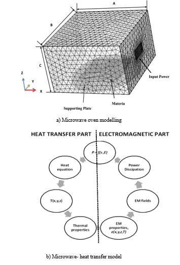 Figure 1. Microwave oven modelling and microwave-heat transfer model
2. Theoretical study
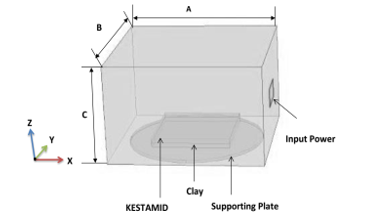
The schematic and modeling diagram of microwave oven prepared for this study is shown in Figure 1. The microwave multimode applicator is represented by a metallic box of rectangular shape, (A = 354 cm, B = 337mm and C = 215 cm), typical of many industrial and microwave multimode applicator. The excitation port is a rectangular waveguide and the fundamental mode is TE10, which operates at 2.45 GHz frequency. The sample is placed over a cylindrical shaped glass plate at z = 10mm, which is located near to the bottom of the applicator. For this particular study rectangular shape clay sample was chosen. The results obtained in this work can be applied in industrial processes where pieces of clay must be dried. Figure 1a shows schematic diagram of microwave oven, the computational domain was meshed using a tetrahedral element. The complete mesh consists of 239920 domain elements, 25550 boundary elements and 831 edge elements. Figure 1b shows microwave and heat transfer model, which is the relation between electromagnetic field and temperature distribution. The heating source is provided by the microwave dissipated power. Also the temperature variation during microwave heating process causes variations in electromagnetic properties. In this study, the distribution of electromagnetic equation inside the cavity and sample has been solved by the well-known Maxwell’s equations, which can be reduced, in the frequency domain with the aid of the following vector-wave equation [1];
![]() where is the vector’s electric field, ω is the angular frequency, µ is the magnetic permeability, and ɛ is the dielectric complex permittivity of the medium, given by [2];
where is the vector’s electric field, ω is the angular frequency, µ is the magnetic permeability, and ɛ is the dielectric complex permittivity of the medium, given by [2];
![]() where ɛ0 is the vacuum permittivity, ɛ’ is the dielectric constant, ɛ’’ is the loss factor, and σ is the conductivity of the medium. The ability of a dielectric material to absorb microwaves and store energy is given by the complex permittivity of the medium.
where ɛ0 is the vacuum permittivity, ɛ’ is the dielectric constant, ɛ’’ is the loss factor, and σ is the conductivity of the medium. The ability of a dielectric material to absorb microwaves and store energy is given by the complex permittivity of the medium.
The ratio of the dielectric loss to the dielectric constant is known as the loss tangent (tan δ) which is given as;
Hence with values of less dielectric constant and large values of loss tangent or dielectric loss, materials couple with microwave with great efficiency. In addition, the dielectric properties of a material depend upon the temperature, frequency and the composition of the material.
The efficiency of the system is calculated as, the ratio of the absorbed power by the material to be heated (Pb) to the microwave input power (??);
The above mentioned equations with the proper boundary conditions of the metallic walls and the waveguide excitation are used to find the electric field distribution and heating efficiency during microwave heating.
3. Results and discussion
The above mentioned equations have been applied to study the effects of different dielectric properties of clay samples placed inside multimode microwave applicator as shown in Figure 1b for efficient microwave heating. The sample is heated for 5 minutes at 2.45 GHz operating frequency inside the multimode microwave applicator with initial temperature of 9 . The applicator is fed 900 W for each simulation works through the rectangular waveguide. The sample is placed over a cylindrical shaped glass plate, which is located near to the bottom of the applicator. The dielectric values used for each simulation and experimental work is measured by network analyzer (Agilent, E506 1B) instrument and two parallel 200mm probe at 2.45 GHz frequency. Table 1 show the samples’ dielectric permittivity used in all the simulation and experimental works.
Table 1. Dielectric characteristics of the clay samples
| ε’ | tan δ (10-3) | |
| Sample 1 | 90 | 47.22 |
| Sample 2 | 77.10 | 119.19 |
| Sample 3 | 59.99 | 187.19 |
| Sample 4 | 52.60 | 239.35 |
For this particular study, first, we used four different dielectric property values as shown in table 1 to investigate the effects of dielectric properties on the performance of microwave heating. Later, we investigated the influence of additional dielectric property value located inside multimode applicator on performance of microwave heating, which is located at the top side of sample material by using KESTAMID dielectric slab of 1 cm thickness. KESTAMIDs’ relative permittivity is εr = 3.7.
Microwave heating efficiency is greatly affected by geometry and size of the sample, its dielectric properties, operating frequency, applied power, its placement inside the applicator, size and geometry of the applicator. However, in this study we will observe and discuss only the effects of the samples’ dielectric properties while keeping the other factors constant for the entire simulation and experimental work.
The dielectric properties of the samples’ located inside the applicator influences the amount of the microwave power absorbed by the sample during its heating process. Dielectric properties of the material to be heated are functions of temperature, frequency and the composition of the material. The change of the dielectric properties with temperature influences the standing wave pattern inside the cavity and thus the microwave absorption. However, for this study we kept the effects of temperature and frequencies on dielectric properties of the sample constant for the purposes of simplicity in electromagnetic field and related calculations.
Figure 2a shows the electric field distribution over the clay sample 1 during microwave heating process for rectangular shaped sample. The simulation result show that the electric field intensity is stronger near to the top and bottom walls of the microwave applicator, and the weakest is located in the middle of the microwave applicator. This variation in electric field distribution leads to different microwave efficiency. From the simulation, the obtained absorbed power by the sample during microwave processing is 335.93 W. From this we calculated the efficiency of the system as η =37.33%.
To validate the simulated electric field distribution of clay samples, experimental works had been done to measure temperature distribution. A thermal fax paper was placed on the top of the sample before microwave heating and placed inside the applicator. Figure 2b shows the stain made by clay sample 1 during microwave heating. The stains obtained on the fax paper agree with the hot and cold spots generated during microwave heating. The temperature pattern over the samples was measured by the laser thermometer as shown in figure 2c.
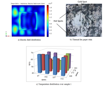 Figure 2. Electric field distribution, Thermal fax paper stain and temperature distribution of sample 1 (εr = 90-j4.25) during microwave drying.
Figure 2c represents temperature distribution pattern for sample 1, generally coincides with the simulated electric field distribution. For example, at the region of maximum electric field intensity on sample 1, V= 23.193 kV/m and 28.521 kV/m, the temperature that rises over sample 1 is also at the maximum; i.e., 61 and 67 , respectively. Also for the other samples it shows that, at maximum electric field intensity region, the temperature rise is also maximum and at lower electric field region, the temperature rise is low. In the middle zone of the multimode applicator, the temperature rises of sample materials are lower. From the above experimental result, we can see clearly the direct relationship between the electric field intensity and temperature pattern, the temperature rise is affected by the sample’s dielectric properties, which also affected the system’s overall efficiency, and this validates our work.
Figure 3 shows the electric field and temperature distribution over the clay samples and inside multimode applicator during microwave heating process for rectangular shaped samples. Figure 3a shows electric field distribution over sample 2. The power absorbed by the sample is 380.34 W. From here the efficiency of the system is η = 42.31%. Figure 3b shows the temperature distribution pattern over sample 2. After the microwave heating, the minimum and maximum temperature over the heated material was measured as minimum temperature Tmin = 53 and maximum temperature Tmax=71 The average temperature distribution was calculated as 62 .
Figure 4 shows the electric field and temperature distribution over the clay samples and inside multimode applicator during microwave heating process for rectangular shaped samples. Figure 4a shows electric field distribution over sample 3. The power absorbed by the sample 3 is 430.83 W. From this the calculated efficiency of the sample is 47.87%. Figure 4b shows the temperature distribution pattern over sample 3. After the microwave heating, the minimum and maximum temperature over the heated material was measured as minimum temperature Tmin = 55℃ and maximum temperature Tmax=71℃. The average temperature distribution was calculated as 63 ℃.
Figure 5 shows the electric field and temperature distribution over the clay samples and inside multimode applicator during microwave heating process for rectangular shaped samples. Figure 5a shows electric field distribution over sample 4. Figure 5a shows the electric field distribution over sample 4. The power absorbed by sample 4 is 454.91 W, and from here the calculated system efficiency is 50.55%. Figure 5b shows the temperature distribution pattern over sample 4. After the microwave heating, the minimum and maximum temperature over the heated material was measured as minimum temperature Tmin = 65℃ and maximum temperature Tmax=75℃. The average temperature distribution was calculated as 70 ℃.
Figure 6 shows summary of the results, obtained absorbed power and system efficiency for different dielectric values of rectangular clay samples mentioned in table 1.
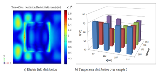 Figure 3: Electric field and temperature distribution over sample 2
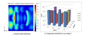 Figure 4: Electric field and temperature distribution over Sample 3
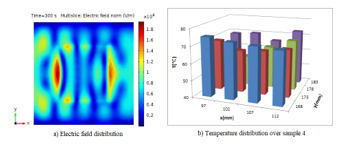 Figure 5: Electric field and temperature distribution over Sample 4
From the above simulated and calculated results, under assumption of similar initial temperature, size and geometry of the sample, samples’ placement inside applicator, frequency, and applicators’ size and geometry, the electric field distribution and efficiency of the system is different for different samples’ dielectric property.
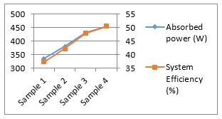 Figure 6. Absorbed power and system efficiency for different clay sample.
Secondly in this extended version, we placed a dielectric slab over the clay sample to see its dielectric property influence on the performance of microwave heating as shown in figure 7. Figure 7 shows the schematic diagram of microwave oven loaded with KESTAMID slab and clay sample.
When an additional dielectric slab is placed around the sample material, the original electric field distribution inside multimode applicator changes, because between the two different materials reflection and transmission of electromagnetic field occurs thus it leads to variation in systems efficiency. In this study, we used rectangular shaped KESTAMID dielectric slabs of 1 cm thickness to place over the clay sample to investigate the influence of adding another dielectric property on the performance of microwave heating inside multimode applicator.
 .Figure 7: Schematic diagram of loaded microwave oven with KESTAMID slab and clay sample.
Figure 8 shows the electric field distribution over clay sample and inside multimode applicator after KESTAMID slab is placed over clay samples having different dielectric property.
Figure 8a shows the electric field distribution over sample 1. From the results obtained from simulation the absorbed microwave power by sample 1 during microwave processing is 464.21 W. From this we calculated the efficiency of the system as η = 51.58%. Figure 8b shows electric field distribution for clay sample 2. The power absorbed by sample 2 is 504.61 W. From this the efficiency of the system is η=56.07%. Figure 8c shows electric field distribution for clay sample 3. The power absorbed by sample 3 is 561.26 W. From this the calculated efficiency of the sample is 62.36%. Figure 8d shows the electric field distribution over sample 4. The power absorbed by sample is 649.09 W, and from here the efficiency of system is 62.19%. Figure 9 shows summary of the
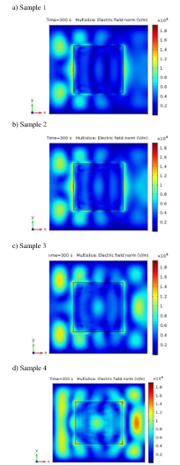 Figure 8: Electric field distribution inside multimode applicator during dielectric slab placement over the clay sample; a) sample 1 b) sample 2 c) sample 3 d) sample 4.
obtained results for different dielectric values of rectangular clay samples when KESTAMID slab is placed over the material to be heated.
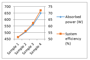 Figure 9. Absorbed power and systems’ efficiency of different clay samples (KESTAMID slab on top of clay sample).
As shown in Figure 8 and relating numerical analysis, we can see that the electric field distribution and efficiency of the system is greatly affected by the newly added dielectric slabs’ dielectric property. The electric field distribution shows more uniformity in Figure 8 compared to Figure 2,3,4 and 5. However, in Figure 8 the electric field distribution over clay sample materials having high loss tangent values shows more uniformity compared to materials having low loss tangent values. Also placing KESTAMID slab improves system efficiency by 22% compared to the efficiencies obtained without placing a dielectric slab.
Finally, from the analysis of the influence of the clay sample employed in the microwave heating process, it can be concluded that different samples’ dielectric permittivity produce different levels of efficiency. Also by placing a dielectric slab over the material to be heated can improve systems efficiency. Therefore, the dielectric properties of the material located inside multimode applicator is of utmost importance when trying to design an efficient microwave oven.
4. Conclusion
In this paper, the effects of dielectric properties of clay samples on the performance of microwave heating have been investigated and discussed. Microwave heating is affected by different parameters like the placement of a material inside multimode applicator, size and shape of the material, operating frequency, dielectric properties of the material, size and shape of the applicator, and numbers and positions of the waveguide over the applicator. However, in this paper only the dielectric properties of the material have been studied. This has been done by keeping constant the other factors throughout the work in order to see solely the effect of the dielectric properties changes on system efficiency. Different clay samples’ dielectric property gives different system efficiency. From the obtained simulation and experimental results, the materials with high loss tangent values give maximum system efficiency compared to the others. In other hand placing another dielectric slab (in this case KESTAMID) over the clay sample improves both electric field distribution pattern and system efficiency. Placement of KESTAMID slab over the material to be heated improved the efficiency of the system by 22%. Also a material with high loss tangent value shows more uniform electric field distribution compared to the others. However, different dielectric slab thickness also has an effect on the performance of the microwave heating; it will be considered in the future works.
Conflict of Interest
The authors declare no conflict of interest.
Acknowledgment
The authors are thankful to Assoc. Prof. Dr. Güray SALİHOĞLU of Uludag University (Department of Environmental Engineering) and Assoc. Prof. Dr. Filiz ALTAY of Istanbul Technical University.
- A.C. Metaxas, R. J. Meredith, Industrial Microwave Heating, Peter Peregrinus, 1983.
- David K. Cheng, Field and wave electromagnetics. John Wiley & Sons, Inc.,
- H. Feng, Y. Yin, J. Tang, “Microwave Drying of Food and Agricultural Materials: Basics and Heat and Mass Transfer Modeling”. Springer-Verlag, Food Eng Rev, 4(2), pp. 89-106, 2012. https://doi.org/10.1007/s12393-012-9048-x
- J. Vrba, M. Stejskal, M. Pourova, “Microwave drying machine for textile materials”, in proceedings of the 2009 European Microwave Conference (EuMC), Rome, Italy, pp. 1121-1124, 2009. IEEEXplore, DOI: 10.23919/EUMC.2009.5296116.
- L, A Jermolovicius, J. T. Senise, R. B. D. Nascimento, “Microwave Drying of Zinc Sulfate”, in 2007 SBMO/IEEE MTT-S International Microwave & Optoelectronics Conference, Brazil, pp. 284-286, 2007. IEEEXplore, DOI: 10.1109/IMOC.2007.4404264
- G.A. Morozov, O. G. Morozov, R. R. Samigullin, A. R. Nasibullin, “Application of Microwave Technologies for Increase of Efficiency of Polymeric Materials Recycling”, 2011 VIII International Conference on Antenna Theory and Techniques (ICATT), Kyiv, Ukraine, pp. 321-323, 2011. IEEEXplore, DOI: 10.1109/ICATT.2011.6170771
- Y.Hong, Bai. Lin, H. Li, H. Dai, C. Zhu, H. Yao. “Three-dimensional simulation of microwave heating coal sample with varying parameters”, Applied Thermal Engineering, Vol. 93, pp. 1145–1154, 2016. https://doi.org/10.1016/j.applthermaleng.2015.10.041.
- N. Makul, P. Rattanadecho, ”Microwave pre-curing of natural rubber-compounding using a rectangular wave guide”, International Communications in Heat and Mass Transfer, Vol. 37, 914–923, 2010. https://doi.org/10.1016/j.icheatmasstransfer.2010.03.001.
- Narumitbowonkul, P. Keangin, P. Rattanadecho, “Numerical and Experimental Analysis of Temperature Distribution and Electric Field in a Natural Rubber Glove during Microwave Heating”, International Science Index, Mechanical and Mechatronics Engineering, 9(3), pp. 518-524, 2015. DOI: 10.1999/1307-6892/10000910.
- A. Esin, N. Mahmutyazıcıoğlu, S. Altıntaş, “Drying and Sintering of Ceramic Based Parts Using Microwave Heating”, Key Engineering Materials, Vols. 264-268, pp. 731-734, 2004. https://doi.org/10.4028/www.scientific.net/KEM.264-268.73
- S.K. Shah, M. A. Joshi, “Application of Microwave Heating In Vacuum for Bagasse Drying”. Proceedings of the 2008 International Conference on Recent Advances in Microwave Theory and Applications, Jaipur, India, pp. 477-479, 2008. IEEEXplore, DOI: 10.1109/AMTA.2008.4763153.
- D. S. Rajpurohit, R. Chhibber, “Design Optimization of Two Input Multimode Applicator for Efficient Microwave Heating”, International Journal of Advances in Microwave Technology (IJAMT), 1(3), 68-73, 2016.
- J.Monzo-Cabrera, J. Escalante, A. Diaz-Morcillo, A. Martinez-Gonzalez, D. Sanchez-Hernandez, “Load matching in multimode microwave-heating applicators based on the use of dielectric layer moulding with commercial materials”, Microwave Opt Technol Lett, 41(5), pp. 414–417, 2004. https://doi.org/10.1002/mop.20156.
- M.E. Requena-Perez, J. L. Pedreno-Molina, M. Pinzolas-Prado, J. Monzo-Cabrera, A. Diaz-Morcillo and D. Sinchez-Hernandez, “Load matching in multimode microwave-heating applicators by load location optimization”, Proceedings of the 34th European Microwave Conference, , Amsterdam, The Netherlands, IEEE, Vol. 3: pp. 1549–1552, 2004. IEEEXplore, DOI: 10.1109/EUMC.2004.183902.
- J.L. Pedreno-Molina, J. Monzo-Cabrera, M. Pinzolas, “A new procedure for power efficiency optimization in microwave ovens based on thermographic measurements and load location search”, International Communications in Heat and Mass Transfer, 34(5), 564-569, 2009. https://doi.org/10.1016/j.icheatmasstransfer.2007.02.002
- I. A. Ali, “Effect of load on the heating efficiency and temperature uniformity in multimode cavity applicators”, Taylor & Francis Group, journal of microwave power and electromagnetic energy, 50(2), 123-137, 2016. http://dx.doi.org/10.1080/08327823.2016.1190170.
- G.Brodie, “The influence of load geometry on temperature distribution during microwave heating”, Transactions of the ASABE (American Society of Agricultural and Biological Engineers), 51(4), pp. 1401-1413, 2008. DOI: 10.13031/2013.25224.
- W.W. Cha-um, P. Rattanadecho, W. Pakdee, “Experimental analysis of microwave heating of dielectric materials using a rectangular wave guide (MODE: TE10) (Case study: Water layer and saturated porous medium)”, Experimental Thermal and Fluid Science, 33(3), 472–481, 2009. https://doi.org/10.1016/j.expthermflusci.2008.11.008
- S.A. Mekonnen, S. Yenikaya, G. Yenikaya, G. Yilmaz, “Effects of sample’s dielectric property on the performance of microwave heating“, proceedings of 2017 10th International Conference on Electrical and Electronics Engineering (ELECO), Bursa, Turkey, pp. 1440 – 1443, 2017.