Using Input Impedance to Calculate the Efficiency Numerically of Series-Parallel Magnetic Resonant Wireless Power Transfer Systems

Adv. Sci. Technol. Eng. Syst. J. 3(3), 38–42 (2018);
 DOI: 10.25046/aj030305
Analysis of magnetic resonant wireless power transfer systems aims to achieve maximum efficiency of the power transfer. From the analysis we wish to derive the maximum power and the frequency at which this occurs. This paper presents a method to estimate these two required values and to achieve this requires the solution of the input impedance equation numerically. The frequency of the maximum efficiency is found when the imaginary of the input impedance is close to zero, and it could be different to the natural resonant frequency. We estimate the efficiency value which depends on the real value part of the input impedance. The proposed method has been applied to one of the four types of possible connections; a series-parallel (SP) connection although similar approaches could be applied to the others. In some cases the maximum efficiency shifts away from the resonant frequency. Therefore, this paper shows how to use the same equations to achieve maximum efficiency at resonance and suggests a design method to achieve this practically.
1. Introduction
This paper is an extension of work originally presented in 2017 IEEE International Conference on Circuits, System and Simulation [1]. Where the impact of connection type on the efficiency of magnetic resonant wireless power transfer systems is studied. There are four potential types of connection in the wireless system due to the resonance type in the transmitter and the receiver; they are: series-series (SS); series-parallel (SP); parallel-series (PS); and parallel-parallel (PP). The equivalent circuit of each type can be expressed by applying Kirchhoff’s law of voltage on each loop in the circuit producing a set of equations [1]. This is called the impedance matrix representation. The effect of changing the load resistor and the gap between the two coils is studied for each connection.
As a near field technology, magnetic resonant wireless power transfer systems can achieve high efficiency in specific conditions. Where the efficiency of the maximum transfer of power is affected by several factors; these are the resonant frequency, the parameters of the coils (inductance, size, and shape), the distance between them and so the mutual inductance, the load resistor, and the connection type of the transmitter and the receiver [1],[2]. To improve the performance of the wireless system, it is important to calculate the efficiency and understand how it is affected by each factor.
Generally, there are two main methods to analyse the system. These methods are coupled mode theory (CMT) and circuit theory (CT) [3]. In the former method (CMT), the system can be described as differential equations [4], [5], [6]. However, according to [7] this method is complicated, undesirable and inconvenient. Therefore researchers tend to use the equivalent circuit for magnetic coupled systems.
The second method (CT) is more familiar to circuit designers than the coupled-mode theory used by the physicists. In this method, the magnetic coupling is represented as the mutual inductance between the two coils. The equivalent circuit of the wireless power transfer system can be formulated as a two port network, which can be represented by either impedance matrix or scattering matrix [5]. Under this main concept of (CT), many researchers have used different modes with different names to study magnetic resonant wireless power transfer systems, such as magnetic resonant coupling (MRC) [7], [8], [9], and reflected load theory (RLT) [4], [10], [11], [12].
The (MRC) method is used to study magnetic resonant wireless power transfer systems by applying a scattering matrix [7], [8], [13]. They use this method because the practical measurement of scattering parameters is more convenient than other methods at high frequencies.
The (RLT) method is commonly used to analyse transformers by electrical engineers, and it can be used to analyse magnetic resonant wireless power transfer systems. The method states that the current in the transmitter coil is dependent on the load in the receiver coil, and the reflected load in the transmitter is not always the same as the actual load [4].
Starting with the impedance matrix representation to express the wireless system, this paper presents another mode to calculate the maximum efficiency of the transfer power and its associated frequency which can be different than the resonant frequency in some cases. Series-parallel type connection has been chosen to examine the method and calculate the required values. The paper also includes an explanation of the previous mode developed in [1]. The results of the two modes are compared in order to evaluate the new mode and show the differences in the calculation methods.
2. Theoretical Analysis
The transmitter of series-parallel magnetic resonant wireless power transfer system consists of a coil (L1) in serial with a capacitor (C1). While the receiver coil (L2) is in parallel with the capacitor (C2), as shown in Fig. 1. The two capacitors are chosen to make the two coils resonate at the same frequency. The voltage source (VS) of the system has an internal resistance of (RS); and RL is the load resistor. The circuit can be presented as follows:
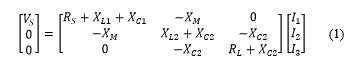 Where XL=2πfL and XC=1/2πfC; f is the frequency and fo is the selected frequency for resonance. Equation (1) can be rewritten in a different way.
![]() Through the following steps, the efficiency of the maximum transfer power can be found:
Through the following steps, the efficiency of the maximum transfer power can be found:
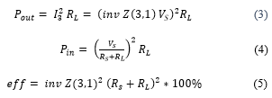
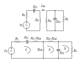 Figure 1: Equivalent circuit of magnetic resonant coupling series-parallel antennas in two forms
3. New Mode of Efficiency Calculation
Another way to calculate the efficiency is as follows:
![]() It can be found from equation (2) that:
It can be found from equation (2) that:
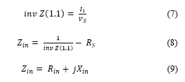 Where Rin and Xin are the real and the imaginary parts of the input impedance, respectively.
Firstly, it is observed that maximum efficiency occurs when the imaginary part of the input impedance is equal to zero. Therefore, the frequency of maximum efficiency (even if it is different than the original resonant frequency) can be found from:
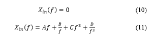 The values of A, B, C, and D depend on the parameters of the circuit. It is apparent that the equation for Xin is complicated and does not have an analytic solution. Therefore, it has to be solved numerically in order to calculate the required frequency. The
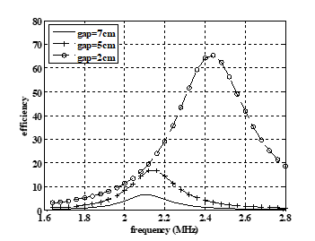 Figure 3: Efficiency versus frequency at different gaps, RL=50Ω
second step is to find the value of the maximum efficiency which is achieved by finding the real part Rin at that calculated frequency. The equivalent circuit in this stage is shown in Fig.2. Assuming maximum transfer of power the maximum efficiency (eff) is derived as:
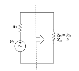 Figure 2: Equivalent circuit at the maximum transfer of power
4. Results and Discussion
The representation of the series-parallel circuit is modelled in Matlab to calculate the mutual inductance and the efficiency of the two modes. To support the theoretical results, several experiments have been conducted. In this work a set of two circular pancake coils are used in all experiments as the primary and secondary. Each coil has 2.9 cm inner radius and 8 cm outer, with 17 turns and an inductance equal to 31.4µH. In addition to that, a set of capacitors equal to 185pF, tuned to work at 2.088MHz were connected to the coils in series in the transmitter and in parallel in the receiver.
|
|
4.1. Effect of Distance
Starting with a 50Ω load resistor, the efficiency is found at different gaps between the two coils 7 cm, 5 cm, and 2 cm. Figure 3 shows efficiency versus frequency calculated by equation (5). It is clear from the figure that the maximum efficiency increases and shifts away from the original resonant frequency for small gaps. The table contains the maximum efficiency and the associated frequency calculated by equations (10-12) for the same gaps between the two coils.
Table: Maximum efficiency and associated frequency calculated by the input impedance for the different cases
| Gap (cm) | 2 | 5 | 7 | 5 | 5 |
| RL (Ω) | 50 | 50 | 50 | 100 | 1k |
| f (Xin≈0) (MHz) | 2.43 | 2.14 | 2.11 | 2.14 | 2.17 |
| Rin (Xin≈0) (Ω) | 13 | 2.35 | 0.87 | 4.7 | 45.77 |
| effmax (%) | 65.5 | 17.15 | 6.7 | 31.4 | 99.8 |
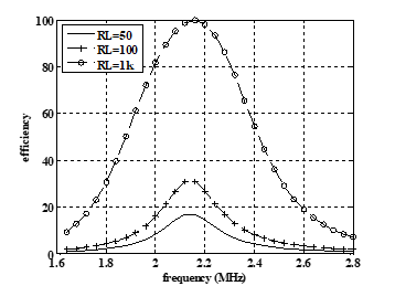
4.2. Effect of Load Resistor
Working on different load resistor values affects the efficiency of the wireless system. Figure 4 shows the system has high efficiency with small load at the same distance. In all cases there is a small shift in the maximum efficiency point compared to the resonant frequency.
In order to show the shift in maximum efficiency, the efficiency and input impedance curves including the real and the imaginary parts for the last case in the Table, all are shown in Fig. 5. The figure also defines the original resonant frequency at 2.088MHz.
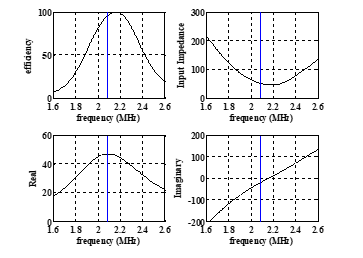 Figure 5: Efficiency, input impedance, real, and imaginary versus frequency, RL= 1kΩ, gap=5cm
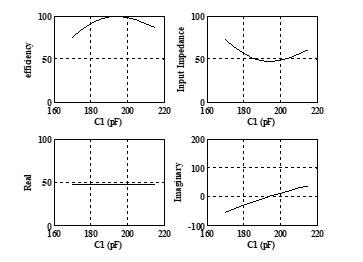 Figure 6: Efficiency, input impedance, real, and imaginary versus C1, at f0=2.088MHz, RL= 1kΩ, gap=5cm
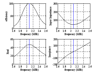 Figure 7: Efficiency, input impedance, real, and imaginary versus frequency, RL= 1kΩ, gap=5cm, C1=195pF
The maximum efficiency and the associated frequency (calculated by the input impedance and included in the Table) are well matched; the curves are shown in Fig. 3-5.
5. Moving the Maximum Efficiency to the Resonant Frequency
For feasible and efficient systems, it is important to obtain maximum efficiency at the resonant frequency. Otherwise, the system might lose a significant part from the transfer power. It is obvious from the previous figures that there is no symmetry in the curves, and the maximum efficiency shifts to one side of the resonant frequency. It can be concluded that tuning one of the capacitors is sufficient to re-merge the maximum efficiency with the original resonant frequency. This is possible by using the input impedance equation (the imaginary part) in a different way:
![]() Using the resonant frequency to solve the last equation provides the capacitor value C1 that achieves the maximum efficiency at that frequency, as shown in Fig. 6. The figure shows that C1 =195pF is the required value; it can be calculated numerically from equation (13). Using the calculated value of C1 equates the imaginary part of the input impedance to zero and then matches the highest efficiency with the resonant frequency, as shown in Fig.7.
Using the resonant frequency to solve the last equation provides the capacitor value C1 that achieves the maximum efficiency at that frequency, as shown in Fig. 6. The figure shows that C1 =195pF is the required value; it can be calculated numerically from equation (13). Using the calculated value of C1 equates the imaginary part of the input impedance to zero and then matches the highest efficiency with the resonant frequency, as shown in Fig.7.
Applying the proposed method empirically to improve the performance of the system by moving the maximum efficiency to the original resonant frequency is achieved by measuring the phase shift between the real and the imaginary parts of the input impedance. The phase shift indicates the imaginary part; its zero value means that the imaginary part of the input impedance is zero and this is the required value from the design, according to the following formula:
![]() The suggested design is shown in Fig.8. It is suitable for specific ranges in the series-parallel parameters, where a capacitive effect is observed in the input impedance of the wireless system. To reduce this effect, increasing of the capacitor in the transmitter side is needed. The figure shows that the capacitor in the transmitter side is tuned according to the calculation of the phase shift of the input impedance.
The suggested design is shown in Fig.8. It is suitable for specific ranges in the series-parallel parameters, where a capacitive effect is observed in the input impedance of the wireless system. To reduce this effect, increasing of the capacitor in the transmitter side is needed. The figure shows that the capacitor in the transmitter side is tuned according to the calculation of the phase shift of the input impedance.
To design a system theoretically the steps are: specify the parameters of the circuit; choose the resonant frequency; and calculate the required value of the tuning capacitor to achieve maximum efficiency at resonance. To apply the system practically requires the following steps: calculate the phase shift of the input impedance; automatically tune the transmitter capacitor to reduce the phase shift; and then reduce the imaginary part of the input impedance.
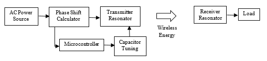 Figure 8: Block diagram of the suggested design
6. Conclusion
Having more than one mode to calculate efficiency is more convenient and allows results to be compared to one another.
The proposed method is a quick and simple mode to identify i) the maximum efficiency in a series-parallel wireless power transfer system and ii) the associated frequency. The idea is to equate the imaginary part of the input impedance with zero to find the frequency; and then calculate the maximum efficiency at that frequency from the real part.
Initially, the proposed method was applied to the series-parallel case. In our future work, this method can be applied on the other topologies of resonant wireless power systems.
This work markedly improves the efficiency of a series-parallel wireless system. The limitations of achieving this practically is limited to specific ranges of parameters where a capacitive effect is observed in the input impedance.
Conflict of Interest
The authors declare no conflict of interest.
- T. Thabet, and J. Woods, “Impact of connection type on the efficiency of wireless power transfer systems.”, in 7th IEEE International Conference on Circuits, System and Simulation (ICCSS), 2017. https://doi.org/10.1109/CIRSYSSIM.2017.8023200
- T. Thabet, and J. Woods, “An Approach to Calculate the Efficiency for an N-Receiver Wireless Power Transfer System,” IJACSA, 6(9), 91-98, 2015. https://doi.org/10.14569/IJACSA.2015.060912
- X. Wei, Z. Wang, and H. Dai, “A critical review of wireless power transfer via strongly coupled magnetic resonances,” Energies, 7(7), 4316-4341, 2014. https://doi.org/10.3390/en7074316
- O. Rönnbäck, “Optimization of Wireless Power,” Master Thesis, Luleå University of Technology, 2013.
- A. Bodrov, and S.-K. Sul, “Analysis of wireless power transfer by coupled mode theory (CMT) and practical considerations to increase power transfer efficiency,” InTech, 2012. https://doi.org/10.5772/25270
- H. Shim, J. Park, S. Nam, and B. Lee, “A criterion Proposed for Inductive Coupling and Magnetic Resonance Coupling in Wireless Power Transfer System.” in 26th Asia-Pacific Microwave Conference (APMC), 2014. http://ieeexplore.ieee.org/document/7067678/
- T. Beh, M. Kato, T. Imura, and Y. Hori, “Wireless Power Transfer System via Magnetic Resonant Coupling at Fixed Resonance Frequency-Power Transfer System Based on Impedance Matching-,” EVS-25 Shenzhen, China, 2010. https://pdfs.semanticscholar.org/7c5c/1dca95a922971ce5a7e28700876ff29b6448.pdf
- T. Imura, H. Okabe, and Y. Hori, “Basic experimental study on helical antennas of wireless power transfer for electric vehicles by using magnetic resonant couplings.” in 5th IEEE Vehicle Power and Propulsion Conference, 2009. https://doi.org/10.1109/VPPC.2009.5289747
- T.C. Beh, M. Kato, T. Imura, S. Oh, and Y. Hori, “Automated impedance matching system for robust wireless power transfer via magnetic resonance coupling,” IEEE Transactions on Industrial Electronics, 60(9), 3689-3698, 2013. https://doi.org/10.1109/TIE.2012.2206337
- M.Kiani, U.-M. Jow, and M. Ghovanloo, “Design and optimization of a 3-coil inductive link for efficient wireless power transmission,” IEEE transactions on biomedical circuits and systems, 5(6), 579-591, 2011. https://doi.org/10.1109/TBCAS.2011.2158431
- M.Kiani, and M. Ghovanloo, “The circuit theory behind coupled-mode magnetic resonance-based wireless power transmission,” IEEE Transactions on Circuits and Systems I, 59(9), 2065-2074, 2012. https://doi.org/10.1109/TCSI.2011.2180446
- K.S. Kiran, S. Brahma, S. Parida, and R. Behera, “Analysis of inductive resonant coupled WPT system using Reflected Load Theory.” in IEEE International Conference on Power Electronics, Drives and Energy Systems (PEDES), 2014. https://doi.org/10.1109/PEDES.2014.7041987
- T. Imura, and Y. Hori, “Maximizing air gap and efficiency of magnetic resonant coupling for wireless power transfer using equivalent circuit and neumann formula,” IEEE Transactions on Industrial Electronics, 58(10), 4746-4752, 2011. https://doi.org/10.1109/TIE.2011.2112317