Performance improvement of a wind energy system using fuzzy logic based pitch angle control

Adv. Sci. Technol. Eng. Syst. J. 3(3), 30–37 (2018);
 DOI: 10.25046/aj030304
The pitch angle controller maintains the aerodynamic captured power at rated level when the wind speed is above the rated speed. Besides, it can also improve the transient stability occurring in the wind energy system (WES). This paper, therefore, proposes an effective pitch angle control strategy that can deliver the conditioned output power in windy condition and increase the transient stability capability in grid faults. A fuzzy logic method has employed to design the proposed control strategy, Moreover, in this paper some major factors that affect the transient stability have been investigated by deriving steady-state equivalent model of the wind energy system. The simulated results show that the proposed fuzzy logic based pitch angle controller is effective at conditioning the output power and complying with fault ride through requirements for WES in the power system.
1. Introduction
Transient stability enhancement of wind energy system using fuzzy logic based pitch angle controller is a topic of much interest in wind energy studies [1]. Wind energy is perhaps more economical and viable among the other renewable energy resources available for electric power generation. According to predictions it is estimated that, by 2020 wind energy will contributes to about 10 percentage of the world’s electricity [2]. While wind energy is free, its generation involves some operational issues. The main issue that arises is that wind speed is not constant, resulting in large fluctuations in the real power since the output power is proportional to the cube of the wind speed. Another issue of concern is that if a fault occurs in the power network then the induction generator that is generally used in a wind energy system (WES) will not be supplied with the necessary reactive power and this will result in rotor instability [3].
Pitch angle controller limit is one of the ways to regulate the speed of the wind turbine under varying wind speeds. This controller helps to maintain the aerodynamic power at rated value when the wind speed exceeds the rated wind speed. In some reported works [4-9], different methods have been proposed to design the pitch angle controller for regulating the active power at rated value and improve the power quality with frequent wind speed changes. Beside this, pitch angle controller is also employed to stabilize the WES under transient disturbances or faults. The transient stability analysis of a WES is important because of its impact on the utility grid. In the literature some researchers have designed rotor speed control based pitch angle controller to enhance the transient stability [10-13].
Thus, the pitch angle control serves two purposes: In [4-9], they are used to regulate the generator output power at rated value for varying wind speeds while in [10-13], they are used for stabilizing the WES under transient disturbances or post fault operation. A study of the performance of the pitch controller in both these conditions is the subject of this paper. A pitch angle control strategy is proposed which is designed for improving the smoothing of power and transient stability behavior of the WES under disturbances or wind speed variations. Fuzzy logic technique has been employed for the pitch-angle controller design, as it reported best suited in comparison to other types of controllers.
The major contribution of this paper as follows:
- Derived a steady-state equivalent model of the induction generator using analytical approach. The mechanical torque versus rotor speed results were obtained under different pitch angle conditions.
- A fuzzy logic controller (FLC) based pitch angle control system (in power and speed control modes) has proposed, which can enhance the transient stability performance of the WES subjected to severe network disturbances (in speed control mode) and maintain the output power when the wind speed is higher than rated speed (in power control mode).
This paper is structured as follows: Section 2 discusses the system configuration, modeling of wind turbine and induction generator. In section 3, Pitch angle controller basic concept, proposed control strategy, and controller design (PI and fuzzy logic) are discussed in detailed. The simulation results are discussed in section 4. Finally, important conclusions are drawn in section 5.
2. Modelling of Wind Energy System
2.1. Configuration of the studied system
A typical WES that is used for the present simulations consists of a 1.5 MW wind turbine driven induction generator (IG) as shown in Fig. 1. The stator winding of the IG is connected to the point of common coupling (PCC) through a step-up transformer (0.69/25kV) which exports power to the 120kV grid through step-up transformer (25/120kV) and a transmission line ( ) operating at 120kV. The rotor of the IG is driven by a variable pitch wind turbine. A power factor correction capacitor ( ) is connected to the low voltage terminal of the wind turbine generator. It provides required amount of reactive power to the IG for maintaining the terminal voltage. The design based parameters of the generator and wind turbine are given in Appendix-I.
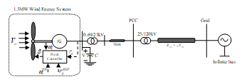 Figure. 1. The studied grid-connected WES
2.2. Wind Turbine Modeling
The developed mechanical power of a typical wind turbine is directly proportional to the cube of wind speed as given:
![]() where, is available wind power, is the air-density (kg/m3), is the turbine swept area (m2) and can be written as , is the wind speed (m/s) and is the power coefficient.
where, is available wind power, is the air-density (kg/m3), is the turbine swept area (m2) and can be written as , is the wind speed (m/s) and is the power coefficient.
The typical wind turbine is characterized by the power coefficient ( ) which depends upon the ratio of rotor-tip speed ( ) and blade pitch-angle ( ). The power coefficient ( ) employed in this study is as follows [14]:
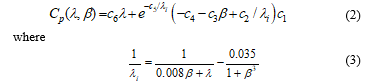 The coefficients are: , , , , and and the tip-speed ratio ( ) can be defined as:
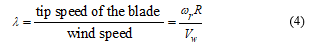 where, R is the radius of turbine rotor [m] and is rotor speed [rad/s]
The mechanical power ( ) shown in equation (1) can be expressed as:
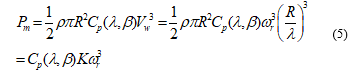 where,
Hence, the mechanical torque output of induction generator (IG) can be derived as [15]:
![]()
According to equations (1) – (4), for different values of pitch-angle ( ), the power coefficient versus tip-speed ratio ( ) curve for the studied system has been obtained as shown in Fig. 2. For different values of wind speed ( ), the turbine output power versus turbine speed characteristics is as shown in Fig. 3.
The relation between mechanical torque ( ) and pitch angle ( ) with respect to rotor speed ( ) as shown in Fig. 4 is obtained using information of Fig. 2 with Eqn. (6). As observed from equation (6), the mechanical power output ( ) of wind turbine depends upon power coefficient ( ) and the rotor speed ( ) of wind turbine. However, the turbine speed varies very little as the fixed speed cage generators have a speed variation range less than 1% [16]. Thus, variation of mechanical power depends mainly on the power coefficient which varies with the tip speed ratio and pitch angle . However, it may be observed that in transient disturbances, tip speed ratio variation is very small [17]. As a result, the mechanical torque mostly depends on the pitch angle ( ). So, it can be noticed from Fig. 4, that the mechanical torque decreases, at the particular point onwards of rotor speed, as the pitch angle increases.
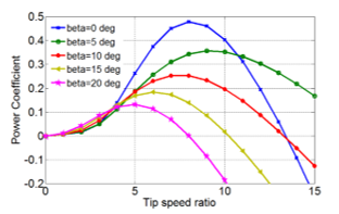 Figure. 2. Wind turbine curve
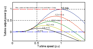 Figure. 3. Turbine Power characteristics
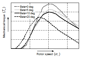 Figure. 4. Mechanical torque versus rotor speed
2.3. Induction generator modeling
The employed test system shown in Fig. 1 can be modeled by the equivalent electrical circuit from induction generator (IG) to PCC is shown in Fig. 5. The steady state equivalent circuit of the IG is as shown Fig. 5 within the box enclosed by dotted lines.
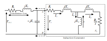 Figure. 5. Electrical equivalent of the test system
According to the IG equivalent circuit, the mathematical expression for stator terminal voltage ( ) of the IG is:
![]() where, is air gap magnetic field induction electro-magnetic-field (EMF) given by
where, is air gap magnetic field induction electro-magnetic-field (EMF) given by
![]() Where magnetizing reactance and is the exciting current of the IG. Now the rotor current can be determined from stator current after deducting as follows:
Where magnetizing reactance and is the exciting current of the IG. Now the rotor current can be determined from stator current after deducting as follows:
![]() and then the corresponding mechanical power input to the IG will be given by
and then the corresponding mechanical power input to the IG will be given by
 where, and are the rotor and stator resistance, respectively and s is the slip which is less than zero for the IG.
To understand the transient stability concept of the studied wind power system it is necessary to calculate the electrical torque of the generator using the electrical equivalent circuit of the system. The Thevenin equivalent circuit obtained from Fig. 5 from the point A and B is as shown in Fig. 6.
Where, Thevenin equivalent voltage is:
![]() and the series parameters are:
and the series parameters are:
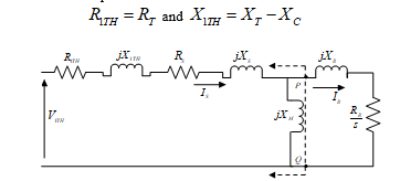 Figure. 6. Reduced Equivalent circuit of the system
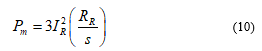
Again, applying the Thevenin concept to Fig. 6 at the point P and Q the further reduced equivalent circuit has been obtained as shown in Fig.8. The Thevenin equivalent voltage obtained as:
![]() and the equivalent Thevenin resistance and reactance can be obtained as: and .
and the equivalent Thevenin resistance and reactance can be obtained as: and .
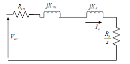 Figure. 7. Complete Reduced Equivalent circuit of the system
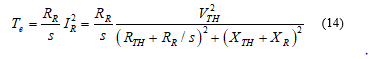
Finally, from the Fig.7, the rotor current can be computed as [18]:
![]() From which, the generator electrical toque can be determined as:
From which, the generator electrical toque can be determined as:
 Generally, the slip ( ) is defined as:
 When the induction machine is operated as generator, the sign convention for the electrical ( ) and mechanical ( ) torques are reversed. Therefore, the mechanical-electrical equilibrium of the IG can be expressed as
![]() Eqn. (16) gives the information that during the network faults the electrical torque ( ) become zero since the voltage at the PCC is zero which causes the generator rotor speed to increase drastically leads to instability of the system. However, by increasing the pitch angle of wind turbine the mechanical toque ( ) can be decreased (see Fig. 4) and thus, generator rotor speed ( ) can be limited/decreased to its normal value as given by Eqn. (16). Thus, the pitch angle controller plays an important role in the operation of a WES to improve the transient stability.
Eqn. (16) gives the information that during the network faults the electrical torque ( ) become zero since the voltage at the PCC is zero which causes the generator rotor speed to increase drastically leads to instability of the system. However, by increasing the pitch angle of wind turbine the mechanical toque ( ) can be decreased (see Fig. 4) and thus, generator rotor speed ( ) can be limited/decreased to its normal value as given by Eqn. (16). Thus, the pitch angle controller plays an important role in the operation of a WES to improve the transient stability.
3. Pitch angle controller
The block diagram of a typical pitch-angle control system is shown in Fig. 8. When the wind speed crosses the rated wind speed ( ), the pitch angle controller modifies the aerodynamic toque to maintain the generator output power at its rated value. The difference between the measured power ( ) and reference power ( ) generates a control signal to the controller , which regulates the output power accordance with error ( ), by modifying the pitch angle.
The pitch-angle control strategy mathematically can be expressed as:
![]() where, and are small-signal state variables of mechanical power and pitch angle, respectively, and is the initial pitch-angle magnitude.
where, and are small-signal state variables of mechanical power and pitch angle, respectively, and is the initial pitch-angle magnitude.
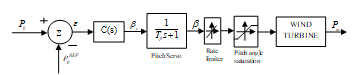 Figure. 8. The typical pitch-angle control system
The optimum pitch angle ( ) from the controller is used as reference to the pitch actuator/servo system. The purpose of the pitch servo is for the correct positioning of the blades. The first order transfer function of the electric or hydraulic pitch servo is as follows:
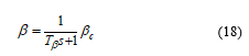 The pitch angle ( ) follows the reference pitch or optimum pitch ( ) by a first order lag with time constant , which is dependent on the pitch actuator. In order to get the realistic response from the pitch control system, the pitch rate and the regulations range of pitch angle are set to and , respectively.
As discussed earlier, the pitch angle controller is generally employed for control above rated wind speed where it regulates the generator output power. Besides, it can also be used to improve the transient stability of the WES. The next subsection discusses how the pitch angle controller can serve these tasks well.
3.1. Control Strategy implemented
The controller shown in Fig. 9 can be operated in two control modes (power and speed) in order to achieve above tasks effectively. The operating mode of the controller can be determined using selection switch. The controller works in power control mode with switch set to input 1 when the wind speed exceeds its rated speed to maintain the output power of the generator at rated value. However, for below rated wind speed controller not in operation where to extract the possible maximum wind power as governed by the Fig. 2. On the other hand, if the rotor speeds of induction generator increase to a threshold rotor speed ( ) due to network disturbances, the controller input is set to input 2, as a result, it works in speed control mode where the transient stability enhancement is achieved with suitable pitch angle generation.
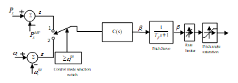 Figure.9. A typical pitch angle controller in power and speed control modes
In order to achieve the effective performance of the wind energy system, the controller C(s) of pitch control system needs to be designed for effective control.
3.2. Proportional Integral (PI) controller
A PI controller was designed using the linearized model of the WES. The Ziegler-Nichols method is employed to determine the appropriate controller gain. When the wind speed is above the rated wind speed for the WES, the PI controller is used to regulate the output power at its rated value by setting a suitable valued pitch angle. Although, this method has a simple structure, good steady-state response and is easy to implement, it exhibits a poor transient response due to use of constant controller gains. Therefore, an alternative method for controller design is proposed using fuzzy logic. It has numerous advantages as fuzzy logic does not require a mathematical modeling of the system and is capable of handling irregularity /nonlinearity. In addition, they provide excellent dynamic responses.
3.3. Design of Fuzzy logic controller
In 1965, Professor Lofti Zadeh proposed the concept of fuzzy logic (FL) [19]. The aim of FL was to develop an output by allowing a set of membership functions(MF) to decide the value of the inputs rather than representation using crisp deterministic values. Fuzzy based controllers have been found to be excellent choices for many control applications, as they imitate human control logic closely. The fuzzy rules are framed on the basis of the expert knowledge gained by the study of the performance of the system over a period of time. The expert knowledge so gained about system output behavior is expressed in terms of membership functions of various control parameters. The block diagram of a conventional FLC (named as Type-1 FLC) is as shown in Fig. 10. It consists of fuzzifier, inference engine and defuzzifier. Here, the fuzzifier converts the crisp value of the input parameter into fuzzy set and depending upon the fuzzy rules framed based on the membership functions for a given parameter of the system and then, fuzzy outputs are obtained with the help of the inference engine. Finally, a defuzzifier converts these fuzzy inputs to a crisp output of the FLC to be used for the control purpose. The employed fuzzy logic based pitch angle controller is shown in Fig. 11.
A. Fuzzification
The input and output variables used for the controller design are expressed with the help of fuzzy sets using linguistic variables. The designed MFs for FLC are shown in Fig. 12. The fuzzy sets for power error ( ) have been defined as: N(Negative), ZE (Zero), XSP(Extra Small Positive), SP(Small Positive), MP(Medium Positive), LP(Large Positive), and XLP(Extra Large Positive). For the change-in-power error ( ) the fuzzy sets are chosen as NB (Negative Big), NS (Negative Small), ZE (Zero), PS (Positive Small), and PB (Positive Big). While for the output pitch-angle control, six membership functions have been defined as ZE (Zero), XS (Extra Small), S (Small), M (Medium), L (Large), and XL (Extra Large) [20,21].
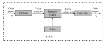 Figure. 10. Schematic diagram of classical (Type-1) Fuzzy Logic Controller
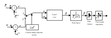 Figure. 11. Fuzzy logic (Type-1) based pitch angle controller
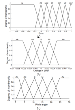 Figure. 12. The designed MFs of FLC (a) Error (b) Change in error (c) Pitch angle
B. Rule base
With help of the experts’ knowledge on the pitch-angle control of the IG wind energy system, control strategies are framed as a set of IF-THEN rules and are as indicated:
If ( is ) and ( is ) then ( is )
Similarly, 35 rules have been defined for all input-output MFs as shown in Table 1.
Table.1. Pitch angle controller rules
|
Change in Error ( ) |
Error ( ) | ||||||
| N | ZE | XSP | SP | MP | LP | XLP | |
| NB | ZE | ZE | ZE | XS | S | M | L |
| NS | ZE | ZE | XS | S | M | L | XL |
| ZE | ZE | ZE | XS | S | M | L | XL |
| PS | ZE | ZE | XS | S | M | L | XL |
| PB | ZE | ZE | S | M | L | XL | XL |
C. Defuzzification
The final stage is defuzzification of the combined input signal .The common defuzzification methods used for the FLC are (a) the first (or last) of maxima,(b) centroid-of-area and (c) mean-of-max methods. In this study, the centroid-of-area method has been used which is the most popular method from among the others. The defuzzification method converts the output fuzzy to crisp output value.
The constants used in the fuzzy logic controllers are scaling gains for input and output gains. The values considered for them chosen by trial and error method as and .
4. Results and Discussions
The employed wind energy system single-line diagram is as shown in Fig. 1. The pitch angle controller is shown in Fig. 11 which can serve for both, excessive wind and network fault conditions. In order to investigate the effectiveness of the control strategy two cases has been considered as below.
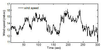 Figure. 13. Wind speed characteristics
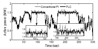 Figure.14. Generator active power
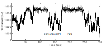 Figure.15. Generator rotor speed
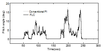 Figure.16. Pitch angle
4.1. Case A: Wind speed disturbances
The wind speed pattern employed for the study is as shown in Fig. 13. Using this wind speed characteristics, the performance of the proposed FLC based pitch angle control was investigated and compared with the results obtained with a conventional PI controller.
The responses of the generator active power, rotor speed and pitch angle controller are shown in Fig.14 -16. Fig. 14 shows the output power of the generator with PI and FLC controllers. Both the controllers can serve well in order to maintain the output power at rated level subjected to above rated wind speed (14 m/s). However, the FLC based controller has maintained the output power at rated level more effectively than PI controller since, the FLC work well with lower overshoot compared to PI controller. Similarly, rotor speed responses with both controllers are obtained and shown in Fig. 15. The pitch angle profiles of the WES with employed controllers are as shown Fig.11.
4.2. Case B: Transient Faults
The transient analysis of the WES has performed using the wind power system configuration shown in Fig. 1. This type of investigation is very important under the severe faults to guarantee the wind farm connection to the grid as per the recent grid codes. We demonstrate the effectiveness of the controller using the most severe fault i.e. a symmetrical fault .At the rated wind speed a three phase short circuit fault has been created time at t=10s for the duration of 150ms. Figures 17 -19 show the performance of the WES with PI and FLC controller.
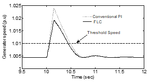 Figure.17. Generator rotor speed
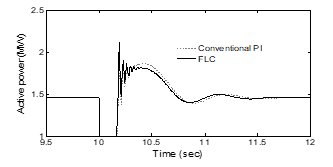 Figure.18. Generator active power
Fig. 17 shows the generator rotor speed variation. It starts increasing rapidly after the fault has been initiated. If the rotor speed exceeds the threshold rotor speed ( ) then the proposed rotor speed-pitch angle controller comes into action and the generator speed becomes stabilized with additional control using PI or FLC controllers. FLC shows better performance than the PI controller. The generator active power is shown in Fig. 18.
The pitch angle controller of the WT with PI and FLC is as shown in Fig. 19. It is noticed that for a large increase in pitch angle control the FLC controller decreases the mechanical torque and hence the rotor speed settles to a stable value.
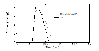 Figure. 19. Pitch angle
Table 2. Comparison of ISE and ITAE for different controllers
| Method | ISE | ITAE |
| Conventional PI | 113.90 | 23500 |
| Fuzzy logic controller | 88 | 17200 |
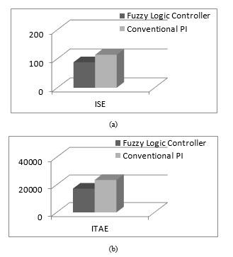 Figure. 20. Graphical representation of comparison of controller indices (a) ISE (b) ITAE
4.3. Controllers performance indices
Various controller performance indexes are available to estimate the controller performs improvement or degradation of the system such as Mean Relative Error (MRE), Integral Absolute Error (IAE), Integral Time Absolute Error (ITAE), Integral Square Error (ISE) and Integral Time Square Error (ITSE). To justify the performance of the controllers properly, the most popularly used indices ISE and ITAE are adopted in this paper and defined as
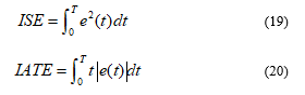 Smaller the value of ISE and ITAE, better the controller performance. The quantitative results are presented in Table 2. It is observed from the Table 2 that the proposed FLC controller has minimum values of ISE and IATE compared to PI controller, therefore, the proposed controller exhibits better controlling performance. Moreover, the graphical representations of ISE and ITAE with both controllers are as shown in Fig. 20 (a) and (b), respectively.
5. Conclusion
This paper, proposes a fuzzy logic based novel pitch angle controller. It not only improves the quality of output power when the wind speed is above rated and high frequent but, can also improve the transient performance of the WES under faults. Two cases has been considered (wind speed disturbance and fault on the network) to demonstrate the effectiveness of the proposed controller. To show the superiority of the proposed controller, the results were compared with proportional-integral based pitch angle controller. It was found from the obtained results that the proposed fuzzy based novel control strategy exhibits superior response than PI based pitch angle controller.
Appendix-I
Table.3. SCIG generator parameters
| Parameters | Values |
| , | 1.5 MW, 0.69 kV |
| 0.004843 p.u., 0.004377 p.u. | |
| 0.1248 p.u., 0.1791p.u. | |
| 6.77 p.u., 5.04 s | |
| 200 kVAR |
Table.4.Wind turbine parameters
| Parameters | Values |
| Rated power | 1.5 MW |
| Rotor diameter | 64m |
| Number of blades | 3 |
| Cut-in wind speed ( ) | 4 m/s |
| Cut-out wind speed ( ) | 25 m/s |
| Rated wind speed ( ) | 14 m/s |
| Generator | SCIG |
Conflict of Interest
The authors declare no conflict of interest.
- K. A. Naik and C. P. Gupta, “Transient stability enhancement of wind energy system using fuzzy logic based pitch angle controller,” 2017 4th IEEE Uttar Pradesh Section International Conference on Electrical, Computer and Electronics (UPCON), Mathura, 78-83 (2017).
https://doi: 10.1109/UPCON.2017.8251026. - The Global Wind Energy Council Belgium. http://www.gwec.net/global-Fig.s/wind-in-numbers/, (accessed 05.04.2017).
- O. Samuelsson, and S. Lindahl, “On speed stability”, Power Syst. IEEE Trans., 20: 1179-1180 (2005).
- M. B. Kadri and S. Khan, “Fuzzy adaptive pitch controller of a wind turbine,” 15th Int. Multitopic Conf. (INMIC), Islamabad, 105-110 (2012).
- Y. Mi, X. Bao, Y. Yang, H. Zhang and P. Wang, “The sliding mode pitch angle controller design for squirrel-cage induction generator wind power generation system,” Proceed. of the 33rd Chinese Control Conf., Nanjing, 8113-8117 ( 2014).
- Y. Mi, X. Bao, E. Jiang, W. Deng, J. Li, L. Ren, and P. Wang, “The pitch angle control of squirrel-cage induction generator wind power generation system using sliding mode control,” 16th European Conf. on Power Electronics and Appli., Lappeenranta, 1-10 (2014).
- M. Al-Saffar and P. Musilek, “Fuzzy logic controller for large, grid-integrated wind farm under variable wind speeds,” 17th International Scientific Conf. on Electric Power Engineering (EPE), Prague, 1-6 (2016).
- D. C. Vega, J. A. Marin and R. T. Sanchez, “Pitch angle controllers design for a horizontal axis wind turbine,” IEEE Int. Autumn Meeting on Power, Electronics and Computing (ROPEC), Ixtapa, 1-6 (2015).
- R. Sakamoto, T. Senjyo, T. Kaneko, N. Urasaki, T. Takagi and S. Sugimoto, “Output power levelling of wind turbine generator by pitch angle control using H- control,” IEEE Pow. Syst. Conf. Expo., 1-6 (2006).
- J. Tamura, “Transient stability simulation of power system including wind generator by PSCAD/EMTDC,” IEEE Porto Power Tech Proceedings, vol.4, EMT-108, (2001).
- O. Wasynczuk, D.T. Man, J.P. Sullivan, “Dynamic behavior of a class of wind turbine generator during random wind fluctuations,” IEEE Trans. on Power Apparatus and Systems, 100: 2873-2845 (1981).
- S. M. Muyeen, M. Hasan Ali, R. Takahashi, T. Murata, J. Tamura, Y.Tomaki, A. Sakahara, and E. Sasano, “Transient Stability Analysis of Grid Connected Wind Turbine Generator System Considering Multi-Mass Shaft Modeling,” Electric Power Components And Systems, 34: 1121-1138 (2006).
- P. M. Anderson and A. Bose, “Stability simulation of wind turbine systems,” IEEE Trans. Power Apparatus and Systems, 102: 3791-3795 (1983).
- T. Ackerman, “Wind power in power system”, John Wiley & Sons. Ltd, (2005).
- R. Strzelecki and G. Benysek, “Power Electronics in Smart Electrical Energy Networks”, Springer, London, UK, (2008).
- B. Wu, Y. Lang, N. Zargari and S. Kouro, “Power conversion and control of wind energy systems”, John Wiley & Sons. Ltd, (2011).
- D. J. Trudnowski, A. Gentile, J. M. Khan, and E. M. Petritz, “Fixed-speed wind-generator and wind-park modeling for transient stability studies,” Power Syst. IEEE Trans. 19: 1911-1917 (2004).
- A. P. Grilo, A. Mota, L. T. M. Mota and W. Freitas, “An analytical method for analysis of large-disturbance stability of induction generators”, Power Syst. IEEE Trans. 22: 1861-1869 (2007).
- L. A. Zadeh, “Fuzzy sets”, Information and control, 8: 338-353 (1965).
- S. Z. Hassan, H. Li, T. Kamal, M. Q. Abbas, M. A. Khan and G. M. Mufti, “An intelligent pitch angle control of wind turbine,” 2017 International Symposium on Recent Advances in Electrical Engineering (RAEE), Islamabad, 2017, pp. 1-6. doi: 10.1109/RAEE.2017.8246144
- S. Z. Hassan, H. Li, T. Kamal, M. Nadarajah and F. Mehmood, “Fuzzy embedded MPPT modeling and control of PV system in a hybrid power system,” 2016 International Conference on Emerging Technologies (ICET), Islamabad, 2016, pp. 1-6. doi: 10.1109/ICET.2016.7813236