
Direct Torque Control Strategy Based on the Emulation of Six-Switch Inverter Operation by a Four-Switch Inverter Using an Adaptive Fuzzy Controller
Volume 3, Issue 2, Page No 346-356, 2018
Author’s Name: Salma Charmia), Bassem El Badsi, Abderrazak Yangui
View Affiliations
University of Sfax, Electrical Department, Sfax Engineering National School, P.O. Box 1173, 3038 Sfax, Tunisia
a)Author to whom correspondence should be addressed. E-mail: charmi.salma@yahoo.fr
Adv. Sci. Technol. Eng. Syst. J. 3(2), 346-356 (2018); ![]() DOI: 10.25046/aj030237
DOI: 10.25046/aj030237
Keywords: Interior permanent magnet synchronous machine, Unbalanced voltage vectors, Balanced voltage vectors, Four-switch three-phase inverter, Six-switch three-phase inverter, Fuzzy logic control

Export Citations
This paper presents a novel direct torque control (DTC) strategy aimed to four-switch three-phase (FSTP) inverter-fed an interior permanent magnet synchronous machine (IPMSM), using a fuzzy logic toolbox in speed control loop. In fact, the introduced DTC approach is based on the emulation of the operation of the standard six-switch three-phase (SSTP) inverter. This fact has been produced thanks to suitable combinations of four unbalanced voltage vectors intrinsically generated by the FSTPI, leading to the synthesis of six balanced voltage vectors yielded by the SSTPI. It has been found from the simulation results that the adaptive fuzzy speed controller implemented for basic and proposed DTC strategies dedicated to FSTPI-fed an IPMSM drives, exhibits interesting performances over different operating conditions, more robustness and less steady-state error especially when there exist motor parameter uncertainties and unexpected load changes occur, compared to the ones yielded by the conventional proportional-integral controller.
Received: 06 March 2018, Accepted: 15 April 2018, Published Online: 30 April 2018
1. Introduction
In recent years, direct torque control strategy is proposed by Takahashi and Depenbrock [1, 2] in the middle of 1980’s. This strategy is increasingly applied for induction machines thanks to its several advantages such as (i) simple control scheme which makes it possible rapid real-time implementation, (ii) fast dynamic torque response and (iii) high robustness and stability against the load torque variations [3, 4] and reference mechanical speed changes. The presented strategy has been successively extended to different kinds of AC machines in various applications [5, 6], including variable reluctance machines [7] and permanent magnet synchronous machines [8], which is becoming popular for variable speed drive systems due to its high efficiency, high power factor, and more robustness. Since then, numerous several investigations carried out in order to improve the performance of the classical DTC strategy. The major focused features are the uncontrolled switching frequency of the inverter and the high torque ripple resulting from using of the stator flux and the electromagnetic torque hysteresis controllers. Commonly, the voltage source inverter (VSI) feeding an IPMSM drives under direct torque control approach is a conventional six-switch three phase inverter which is employed for high efficiency and performance operating of the motor drives. In contrast to this, for economic reasons, reducing the cost of the inverter topology with reduced number of inverter switching devices is still under investigation and has been suggested in [9, 10].
A DTC strategy dedicated to a FSTPI-fed induction machine (IM) drives has been proposed in [11]. In a FSTPI drive system, only two phases of the machine are controlled by power switching devices and the remaining phase is connected directly to the middle point of dc-bus voltage. The resulting modification reduces the number of power switches from six in a SSTPI to four, as in a FSTPI. For the proposed purpose, high-performance in terms of total harmonic distortion reduction allied to control of the inverter switching losses are proven.
Despite a lot of yielded high-performances and cost inverter reduction, the stator phase currents are unidirectional, and hence, this topology is limited to particular industrial applications in the field of motion control. On the other hand, the proposed strategy is penalized by the low dynamic and high torque ripple which is particularly caused by the application of unbalanced voltage vectors to control the stator flux and the torque with a subdivision of the plane limited to four sectors.
An attempt to discard the previously described disadvantages has been proposed where the vector selection table for DTC of IPMSM driven by a FSTPI has been implemented by using of the new approach based on the principle of similarity between FSTPI and SSTPI [12]. The plane is traditionally divided into six sectors and the formation of the required reference space voltage vectors is done in the same way as for conventional SSTPI via employing of the effective vectors.
A further problem of this standard control strategy is that the proportional-integral (PI)-controller with constant parameters can’t easily achieve swift response, small overshooting and fine speed control precision in a wide speed range, especially when there exist motor parameter uncertainties and unexpected load changes occur. More of the past research on variable speed IPMSM drives mainly concentrated on the development of the efficient control algorithms for high-performance drives.
To come up with above inherent drawbacks associated with PI-controller, some advanced techniques in artificial-intelligence based control such as: (i) fuzzy logic control (FLC), (ii) neural network control, (iii) sliding mode control, and (iv) robust control have been developed to achieve high-performance speed control of voltage source inverter feeding-IPMSM drives under direct torque control strategy.
In such a case, this paper proposes a new direct torque control strategy aimed to four-switch three-phase inverter-fed an interior permanent magnet synchronous machine drives, where the speed closed-loop regulator used an adaptive fuzzy logic controller. The introduced strategy is based on the emulation of the six-switch inverter operation owing to the synthesis of an appropriate vector selection table, which is traditionally addressed by two level hysteresis controllers for the stator flux and electromagnetic torque.
A complete comparative study between the conventional proportional-integral controller and the fuzzy logic controller is investigated, considering both transient and steady-state operations and different operating conditions. Basic principles of the introduced approaches are presented and some features illustrating the performance of the developed algorithm are verified and proven.
2. DTC Strategy of FSTPI-Fed an IPMSM Drives
2.1. Direct Torque Control Background
As well known that direct torque control strategy, whose overall block diagram is illustrated in Figure 1, basically consists to control directly and independently the stator flux linkage and electromagnetic torque through an appropriate selection of the inverter control signals, in order to fulfill the requirements as whether the controlled variables need to be increased, decreased, or maintained. In the standard version of DTC scheme, this trend is carried out in accordance with the output of hysteresis controllers of stator flux , of electromagnetic torque and angular displacement of the stator flux vector in the plane.
The dynamic of the stator flux vector is governed by the stator voltage equation expressed in the stationary reference frame as follows in (1):
![]() Where , and are the stator voltage vector, stator current vector, and stator resistance, respectively.
Where , and are the stator voltage vector, stator current vector, and stator resistance, respectively.
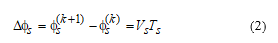
Neglecting the voltage drop ( ) across the stator resistance and taking into account that the voltage vector is constant in each sampling period ( ), the stator flux vector variation turns to be proportional to the applied voltage vector. The expression of turns to be as in (2):
 2.2. Conventional DTC Strategy of Four-Switch Inverter
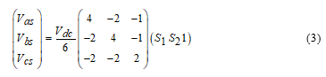
As mentioned earlier, with using of a four-switch inverter system and as shown in Figure 1, two among the three phases of the motor drives are controlled by four insulated-gate bipolar transistors (IGBTs) of the four-switch inverter ( to ) and the third one is connected directly to the middle point of the dc-bus voltage. According to (3), the motor’s stator voltage vectors (abc) are expressed in terms of binary variables and of the upper power switching devices as follow:
 The components of the stator voltage vectors are gained from (abc) ones using Clarke’s transformation are shown in (4):
 The four active voltage vectors ( to ) given in the vector selection table corresponding to the basic DTC strategy (Table 1), are generated from four available combinations of the states of the upper IGBTs. As shown in Figure 2, the former have unbalanced amplitudes and are spaced by , in such away and have an amplitude of and the remaining ones have equally an amplitude of .
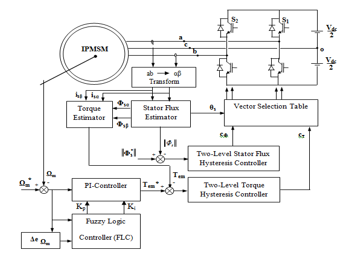 Figure 1. Overall block diagram of direct torque control strategy dedicated to a FSTPI-fed an IPMSM drives.
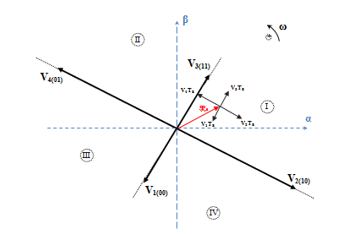 Figure 2. Unbalanced active voltage vectors generated by a FSTPI.
2.3. Vector Selection Table Corresponding to the Proposed DTC Strategy of Four-Switch Three-Phase Inverter
To reduce the speed and torque ripple yielded by the classical four-switch three-phase inverter topology, an optimized vector selection table corresponding to the introduced DTC strategy of FSTPI is originally established for induction machine in 2013 [6] similarly to the basic SSTPI switching table. As reported in the literature, the proposed vector selection table must be defined based on the output states of the instantaneous stator flux and electromagnetic torque two-level hysteresis controllers, together, with the equivalent sector in which the instantaneous stator flux vector is located.
As described previously, the proposed DTC strategy inspired from the earlier one introduced by Takahashi is based on the emulation of SSTPI operation by the FSTPI. This trend is achieved through the generation of six balanced voltage vectors employing the four intrinsic unbalanced ones of FSTPI , where subscript H indicates the half of the corresponding voltage vector (effective).
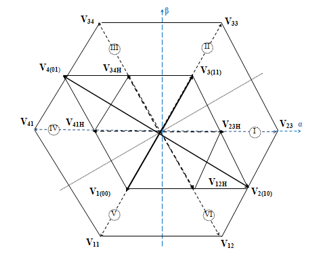 Figure 3. Generation of SSTPI active voltage vectors using four unbalanced voltage.
As shown in Figure 3, these voltage vectors are limited by six symmetric sectors in the Clarke plane and they have the same amplitude of and equally shifted by , like the case of the conventional six-switch three-phase inverter topology. Taking into account of the symmetry of the six sectors, the following analysis of the torque and stator flux variations will be limited to sector I. In order to highlight the appropriateness of the application of the emulation of SSTPI operation, the output variables and of two-level hysteresis comparators have been kept unchanged during two successive sampling periods .
During such sampling period, a half of corresponding voltage vector is applied. Inspired from the approach cited in [6], the adopted control laws to synthesize the corresponding vector selection [Table 2] are defined as:
- the application of ( then ) achieves the control combination ,
- the application of ( then ) achieves the control combination , the application of ( then ) achieves the control combination ,
- the application of ( then ) achieves the control combination .
3. Modeling of Speed Controller-Based an Adaptive Fuzzy Logic
A fuzzy logic controller (FLC) looks at the world in imprecise terms, similar to how a human being perceives information [13]. It converts a linguistic control strategy into an automatic control strategy [14] and fuzzy rules are constructed by expert knowledge or experience database. Unlike the conventional PI-controller, the FLC modeling doesn’t depend on the rating parameters of the motor. Consequently, the FLC offers robust performance under sudden change in command speed and/or load torque disturbances. Besides, the concept of fuzzy set is made precise through the membership functions. The input membership functions transform input analog signals into fuzzy numbers. These latter can be combined through fuzzy rules to generate specific actions.
As shown in Figure 1, the fuzzy logic controller adjusts and optimizes in real time the PI-controller gains ( and ) through fuzzy inference mechanism. As well known that the FLC rule base design involves defining rules that relate the input variables to the output model properties [15]. The designed controller presents two equally inputs and outputs, in this presented work. The input variables of the developed speed controller are: (i) the speed error ( ), and (ii) the time speed error variation ( ), which are calculated at every sampling instant and are given in (5):
 Where is the reference mechanical speed, is the actual mechanical speed, and is the value of speed error at previous sampling time.
The output variables for the illustrated fuzzy logic controller are and . It is well known that the fuzzy controller toolbox generally consists of three main parts: fuzzification process, linguistic rule base, and defuzzification process.
3.1. Fuzzification Process
The input linguistic variables and are converted into fuzzy variables and respectively, that can be identified by the level of membership functions in the fuzzy set. The input fuzzy sets ( and ) are defined graphically by membership functions which are represented by
triangular shapes and with overlapping as shown in Figure 4. The universe of discourse of and are divided into seven overlapping fuzzy sets, namely given as: NB (Negative Big), NM (Negative Medium), NS (Negative Small), ZE (Zero), PS (Positive Small), PM (Positive Medium), and PB (Positive Big). Each fuzzy variable is a member of the subsets with a degree of membership (μ) varying between 0 and 1.
The both output linguistic variables include two fuzzy subsets S (Small) and B (Big). Figure 5 illustrates the membership functions of the output linguistic variables and respectively, which are designed with standard trapezoidal shapes and with overlapping.
Table 3 : Fuzzy control rules table of and respectively
| NB | NM | NS | ZE | PS | PM | PB | |
| NB | B/B | B/B | B/B | B/B | B/B | B/B | B/B |
| NM | S/B | B/B | B/S | B/S | B/S | B/B | B/B |
| NS | S/B | S/B | B/B | B/S | B/B | S/B | S/B |
| ZE | S/B | S/B | S/B | B/S | S/B | S/B | S/B |
| PS | S/B | S/B | B/B | B/S | B/B | S/B | S/B |
| PM | S/B | B/B | B/S | B/S | B/S | B/B | S/B |
| PB | B/B | B/B | B/B | B/B | B/B | B/B | S/B |
3.2. Linguistic Rule Base
The fuzzy rules are conditional statements that use fuzzy operators and membership functions to make control decisions. The reasoning control rules in the system are expressed in “if-then” format. The rules can be written as: If is and is , then is and is . Where , , and denote the fuzzy sets and with i = 1 to 49.
In this step, the input control variables and are processed by a fuzzy inference engine that has the capability of simulating human decision-making based of fuzzy concepts and of inferring fuzzy control actions employing fuzzy implication
and the rules of inference. Depending on inherent law of input and output variables, this system has 49 fuzzy inference rules. According to the speed error and its rate of change , the fuzzy logic rule bases of and at different states can be acquired as shown in Table 3.
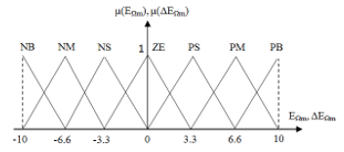 Figure 4. Membership functions of input variables of FLC.
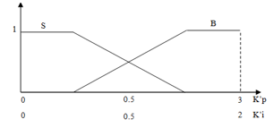 Figure 5. Membership functions of output variables of FLC.
3.3. Defuzzification Process
Once the fuzzy inference results are derived, the control outputs can be acquired from the defuzzification process, to get the crisp values of outputs. In general, the inferred fuzzy action is converted to a crisp value, X, through the widely used weighted average, which is equivalent to center of area (COA) method [16] to yield (6):
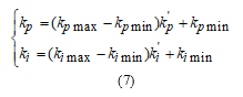
 Where X is a grade value of (it denotes the output variable and/ or ) and is a compatibility (weighing factor; derived by using Mamdani’s minimum fuzzy implication rule). The final actual values can be obtained by using linear transform to the output values. The linear transform formulas of proportional coefficient and integral coefficient are given in (7):
 In a direct torque control strategy, the discrete expression of the reference electromagnetic torque is expressed as:
![]() As shown in (8), the control effects can easily be acquired at different speed demand by dynamically adjusting and in accordance with the speed errors. In the novel fuzzy logic system, the Mamdani’s minimum operation rule is employed for the optimal fuzzy reasoning algorithm.
As shown in (8), the control effects can easily be acquired at different speed demand by dynamically adjusting and in accordance with the speed errors. In the novel fuzzy logic system, the Mamdani’s minimum operation rule is employed for the optimal fuzzy reasoning algorithm.
4. Simulation Based Investigation of Performance of an Adaptive Fuzzy Speed Controller
In order to verify the effectiveness of the proposed adaptive speed controller and to achieve a satisfactory performance of the IPMSM drives fed by a FSTPI for basic and proposed DTC strategies at different dynamic operating conditions, a numerical simulation has been carried out using MATLAB/SIMULINK software.
The ratings and parameters of the IPMSM drives, used in the simulation works, are provided in Table 4. The sampling period is equal to 50μs. The reference stator flux is equal to times its rated value within a dc-bus voltage equal to 400V. The bandwidths used in the stator flux controller and in the electromagnetic torque one are equal to ±0.01Wb. The fixed gains of the standard PI-controller used in the speed control loop are = 2 and = 0.53.
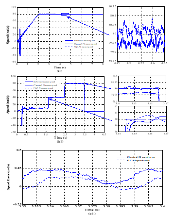 Figure 6. Simulated speed response yielded by conventional DTC strategy at forward motoring operation under constant load torque. Legend (a): motor speeds and its reference in the case of constant mechanical speed, (b) and (c): speed response with its error under variable reference speed.
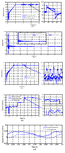 Figure 7. Simulated speed response yielded by proposed DTC strategy at forward motoring operation under constant load torque. Legend (a): motor speed and its reference in the case of constant mechanical speed, (b) and (c): speed response with its error under variable reference speed.
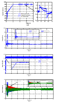 Figure 8. Simulated waveforms of IPMSM drives offered by classical DTC strategy at forward motoring operation under variable load torque. Legend (a1): motor speed and its reference, (b1): electromagnetic torque with its reference, (c1): stator flux with its reference, and (d1): motor stator currents.
Table 4 : IPMSM specifications
| Rated voltage | 208V | Frequency | 60Hz |
| Rated torque | 2N.m | p | 2 |
| Фm | 0.25Wb | rs | 1.93Ω |
| Ld | 44.42mH | Lq | 79.57mH |
| J | 3g.m2 | f | 0.8mN.m.s |
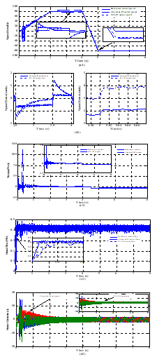 Figure 9. Simulated waveforms of IPMSM drives offered by introduced DTC strategy at forward motoring operation under variable load torque. Legend (a2): motor speed and its reference, (b2): electromagnetic torque with its reference, (c2): stator flux with its reference, and (d2): motor stator currents.
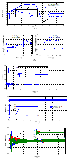 Figure 10. Simulated waveforms of IPMSM drives offered by classical DTC strategy at forward and reversal motoring operation conditions under proportional load torque. Legend (a1): motor speed and its reference, (b1): motor speed error, (c1): electromagnetic torque with its reference, (d1): stator flux with its reference, and (e1): motor stator currents.
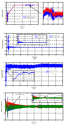 Figure 11. Simulated waveforms of IPMSM drives offered by introduced DTC strategy at forward and reversal motoring operation conditions under proportional load torque. Legend (a2): motor speed and its reference, (b2): motor speed error, (c2): electromagnetic torque with its reference, (d2): stator flux with its reference, and (e2): motor stator currents
The realized works are focused on the motor speed error under transient and steady-state operations, considering different operating conditions, such as: (i) variations of the step reference speed, (ii) sudden change of a load torque, and (iii) variation of the stator resistance, over basic and proposed DTC strategies (subscripts 1 and 2, respectively) using both speed controllers.
Let us consider the start-up of the IPMSM within a ramp-shape reference speed during 2s to reach a constant value of for a constant load torque and under forward motoring operation of the machine. Referring to Figure. 6(a1) and Figure. 7(a2), one can clearly notice that the developed controllers implemented in both direct torque control strategies (basic and proposed ones) yield practically a high dynamic behaviour at transient-state and there is approximately no difference between them at stabile-state operation. Otherwise, the adaptive PI-controller offers quick and smooth speed response with a negligible error during both transient and steady-state operations. Conversely, the conventional PI-controller exhibits a significant speed error especially under transient-state operation for both stratgies and the motor speed can’t reach its reference one at all range time.
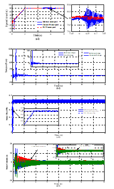 Figure 12. Simulated waveforms of IPMSM drives exhibited by basic DTC strategy at forward motoring operation conditions under stator resistance changes. Legend (a1): motor speed and its reference, (b1): electromagnetic torque with its reference, (c1): stator flux with its reference, and (d1): motor stator currents.
So as to extend an equitable comparison between the designed speed controllers considering the case of sudden changes of reference mechanical speed and for a constant load torque , the simulated starting responses of the four-switch three-phase inverter based IPMSM drives are illustrated in Figures 6.(b1 and c1) and in Figures 7.(b2 and c2). Moreover, the reference mechanical speed increases from 10rad/s to 40rad/s at 1.6s. After 840ms, it increases from its previous value to reach its rated value . Finally, at 3.46s, the speed decreases until it vanishes.
According to Figure 6.(b1) and for the first reference speed change (10rad/s to 40rad/s), with using of basic DTC strategy, the necessary time for mechanical speed to attain its reference value is almost about 45ms for the conventional PI-controller, while with the adaptive fuzzy one, the time response is almost about 24ms.
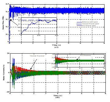 Figure 13. Simulated waveforms of IPMSM drives exhibited by proposed DTC strategy at forward motoring operation conditions under stator resistance changes. Legend (a2): motor speed and its reference, (b2): electromagnetic torque with its reference, (c2): stator flux with its reference, and (d2): motor stator currents.
For second speed change shown in Figure 7.(b2) and with designed FLC regulator implemented in the introduced DTC approach, the speed needs no more than 27ms to reach its desired value, in contrast to the conventional one where the speed remains 63ms to attain the desired one. Thus, as shown in zoomed views of motor speed, one can conclude that the speed response is quick enough under adaptive PI-controller compared to that with the conventional one.
Additionally, as shown in zoom-in view of motor speed responses for both DTC strategies, one can notice clearly that, for the third speed change, the speed has smooth and quick trajectory with FLC system at speed change transition, compared to that exhibited by the classical speed controller. Thus, a good tracking performance has been gained with the developed adaptive PI-controller under application of variable mechanical speed.
Figures 6.(b1 and c1) and Figures 7.(b2 and c2) show that the proposed fuzzy regulator offers a negligible speed error, compared to that provided one by the conventional one which exhibits a higher steady-state error and the motor speed can’t follow its reference value at all range time. So that in fact demonstrates the efficiency of FLC in the speed control loop in terms of swiftness and robustness of system drive when there exist changes of reference speed steps.
Furthermore, so as to highlight the performance and effectiveness gained by the introduced FLC as a speed regulator in DTC scheme, sudden abrupt variations of load torque is applied. Let us consider the start-up of the motor drives within a ramp-shape reference speed during 2s to reach a constant value , at forward motoring operation and for a constant load torque . At 4s, the load torque varied by a reduction of of its initial value and after 2s, it removed to its starting value.
From analysis of Figure 8.(a1) and Figure 9.(a2), one can observe that the steady-state gained by both basic and proposed DTC strategies, is likewise achieved within very short duration for the load torque variations under the proposed adaptive PI-controller. Furthermore, the zoom views of motor speed shown in presented figures prove that the conventional PI-controller provides a higher steady-state error and the motor speed can’t clearly proceed its reference one at all range time. Thereby, the classical PI-controller is more sensitive to load disturbances counter to the expanded adaptive fuzzy one. As a deduction, less speed error and better robustness as regards reference command speed and load torque changes are the most frequently adduced advantages of the adaptive PI-controller over the classical one.
Figures 8.(b1, c1 and d1) and Figures 9.(b2, c2 and d2) illustrate the waveforms of the electromagnetic torque, stator flux and stator currents of the motor drives. Accordingly, one can be seen that both controllers have same motor torque behaviors and stator currents responses which are pure steady-state sine-wave with fewer harmonic at steady-state operation. But it appears that with the using of fuzzy logic system, the motor can start almost with smooth reference torque and low peak thinks to the introduced FLC speed regulator, compared to the classical one.
From analysis of Figure 8.(c1) and Figure 9.(c2), one can clearly notice that DTC strategy using both developed speed controllers in the standard plane leads to high dynamic and reduced amplitude of the stator flux. Furthermore, same remarks can be concluded from the following operation conditions to these mentioned variables. Thus, a good tracking performance has been gained with the developed adaptive PI-controller.
Figures 10.(a1 and b1) and Figures 11.(a2 and b2) show the case of forward and reversal motoring of the IPMSM drives under a proportional load torque. It should be noted that, for positive and negative speeds, the motor speed reaches rapidly and smoothly the reference value using the adaptive PI-controller with negligible steady-state error, which confirms the superiority of the proposed speed controller over the conventional one.
Referring to Figures. 10(c1, d1 and e1) and Figures. 11(c2, d2 and e2), it can be seen that the FLC speed regulator offers reduced amplitude and high dynamic of the stator flux, damped peak of the reference electromagnetic torque thinks to the adapting gains and better forms of the motor stator currents, which confirms the superiority of this designed controller over the classical one, especially for the introduced DTC strategy.
As it is well known that the speed error is caused not only by abrupt change of load torque but also by sudden variation of stator resistance, as shown in Figure 12 and Figure 13. As it is concerned previously, the motor drives is initially accelerated within same ramp-shape of reference speed during 2s to reach a constant value of , with its rated stator resistance and under a constant load torque .
As it is illustrated in Figure 14, the first change of stator resistance from its nominal value 1.93 to its half one (0.965) is applied at 5s. And after 0.5s, the latter value of is raised to reach 2.895. Finally, the last change of stator resistance from 2.895 to its rated value is applied at 6.3s. In all, the suggested value of the stator resistance can be established in (9) as follow:
![]() According to Figure 12.(a1) and Figure 13.(a2), it is distinctly seen that the designed fuzzy controller leads to better and high steady-state performance than that yielded by the conventional one. Like where in different cases discussed earlier, the motor speed is nearly stable and it reaches rapidly and accurately its reference value with a negligible steady-state error, though the stator resistance exceeds its nominal value. Nevertheless, the conventional PI-controller which exhibits considerable and significant overshoots of motor speed, when the variation of stator resistance occurs. Same remarks, which are depicted for the case of the application of a variable load torque, can be noticed here for the obtained curves of the electromagnetic torque, the stator flux and the motor stator currents under the case of variation of the stator resistance of the motor [see Figures. 12(b1, c1 and d1) and Figures. 13(b2, c2 and d2)]. So that validates the merit of using of an adaptive fuzzy speed controller.
According to Figure 12.(a1) and Figure 13.(a2), it is distinctly seen that the designed fuzzy controller leads to better and high steady-state performance than that yielded by the conventional one. Like where in different cases discussed earlier, the motor speed is nearly stable and it reaches rapidly and accurately its reference value with a negligible steady-state error, though the stator resistance exceeds its nominal value. Nevertheless, the conventional PI-controller which exhibits considerable and significant overshoots of motor speed, when the variation of stator resistance occurs. Same remarks, which are depicted for the case of the application of a variable load torque, can be noticed here for the obtained curves of the electromagnetic torque, the stator flux and the motor stator currents under the case of variation of the stator resistance of the motor [see Figures. 12(b1, c1 and d1) and Figures. 13(b2, c2 and d2)]. So that validates the merit of using of an adaptive fuzzy speed controller.
As a summary, for both classical and proposed DTC strategies, the developed fuzzy speed controller leads to reduced ripple of the reference electromagnetic torque during both transient and steady-states operations of the motor, to rapid and high stator flux response and to more balanced and sinusoidal motor stator currents.
Figure 15.(a) illustrates the comparison of total harmonic distortion values of the a-phase stator current (THD) and the electromagnetic torque ripple yielded by the developed strategies under conventional-PI and fuzzy logic controllers in the standard (four-sectors [see Figure 16.(a)]) and proposed (six-sectors [see Figure 16.(b)]) planes (4SPI, 6SPI, 4SFLC and 6SFLC), considering a range of the stator frequency varying from 1.58Hz to 25Hz. The electromagnetic torque ripple is determined by the equations (10) and (11), presented below. According to Figure 15.(a), one can clearly observe that, over the whole stator frequency range, the proposed DTC strategy using both classical and adaptive fuzzy speed controllers generally leads to lower current THD values at all motor speeds, than those offered by basic DTC approach.
On the other hand, one can clearly notice that the proposed adaptive fuzzy controller exhibits the best steady-state performance in terms of current THD values compared to that offered by the conventional PI-controller. So the quantitative comparison confirms the superiority of the adaptive fuzzy controller not only during the dynamic response, but also in the steady-state performance. The electromagnetic torque ripple of developed strategies is calculated using standard deviation function and it is expressed as follow:
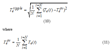 Where N is the sampling number during one short period, is actual electromagnetic torque, and is average electromagnetic torque.
Referring to Figure 15.(b), it should be noted that, over the whole stator frequency range, the electromagnetic torque ripple of the introduced DTC strategy is lower than that offered by the basic DTC one, even if the adaptive fuzzy speed controller or the conventional one is employed. At high stator frequency above 24Hz, the torque ripple of FLC regulator is similar to that of classical PI-controller, under both basic and proposed DTC strategies.
5. Conclusions
This paper dealt with the introduced direct torque control strategy (emulation of SSTPI) incorporating an adaptive fuzzy logic in speed control loop of IPMSM-fed by a four-switch three-phase inverter. According to speed error and its first time derivative, the proportional and integral gains of the proportional-integral speed controller are online adjusted.
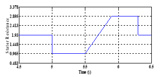 Figure 14. Stator resistance variation.
Simulation-based comparative study between the performances of the developed fuzzy logic controller and the conventional one has been carried out, considering different cases such as: (i) variations of the step reference speed, (ii) sudden change of a load torque, and (iii) variations of the stator resistance.
It has been found that the speed controller-based fuzzy logic toolbox ensures fast dynamic response, less harmonic distortion of the a-phase stator current, reduced torque ripple, more robustness and less steady-state error when there exist variations of the motor parameters and load torque disturbances.
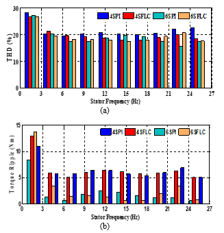 Figure 15. Quantitative steady-state performance comparison yielded by basic DTC strategy and proposed one over conventional-PI and adaptive fuzzy-PI controllers for a constant load torque , at various reference speed levels. (a): THD values, (b): torque ripple.
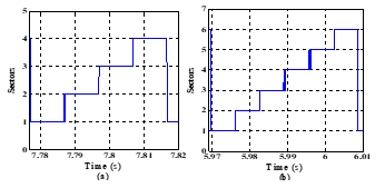 Figure 16. Stationary Clarke plane. (a): four-sectors (4S), (b): six-sectors (6S).
- Depenbrock, “Direct self controlled (DSC) of inverter-fed induction machines” IEEE Trans. Power Electronics., 3(4), October. 1988.
- Takahashi and T. Noguchi, “A new quick-response and high-efficiency control strategy of an induction motor” IEEE Trans. Ind. Appl., 22(5), 820-827, 1986.
- C. D. Sousa, B. K. Bose, and J. G. Cleland, “A fuzzy logic based on-line efficiency optimization control of an indirect vector-controlled induction motor drive” IEEE Trans. Ind. Electron., 42(2), 192-198, Apr. 1995.
- Chen, B. Yang, X. Gu, and S. Xing, “Novel fuzzy control strategy of IPMSM drive system with voltage booster” in Proc. 6th World Congr. Intell on Control Autom, 2, pp. 8084-8087, Jun. 21-23, 2006.
- B. Mohanty, “A direct torque controlled induction motor with variable hysteresis band” 11th International Conference on Computer Modeling and Simulation, 2009.
- El Badsi, B. Bouzidi, and A. Masmoudi, “DTC scheme for a four-switch inverter-fed induction motor emulating the six-switch inverter operation” IEEE Trans. Power Electron., 28(7), 3528-3538, Jul. 2013.
- B. Inderka and R. W. De Doncker, “DITC-Direct instantaneous torque control of switched reluctance drives” IEEE Trans. Ind. Applicat., 39, pp. 1046-1051, July/Aug. 2003.
- Zhong, M. Rahman, W. Hu, and K. Lim, “Analysis of direct torque control in permanent magnet synchronous motor drives” IEEE Trans. Power Electron., 12(3), 528-536, May. 1997.
- A. Welchko and T. A. Lipo, “A novel variable-frequency three-phase induction motor drive system using only three controlled switches” IEEE Trans. Ind. Appl., 37(6), 1739-1745, Nov/Dec. 2001.
- W. vander Broeck and J. D. van Wyk, “A comparative investigation of a three-phase induction machine drive with a component minimized voltage-fed inverter under different control options” IEEE Trans. Ind. Appl., IA-20(2), 309-320, Mar/Apr. 1984.
- Azab and A. L. Orille, “Novel flux and torque control of induction motor drive using four switch three phase inverter” in Proc. IEEE Annu. Conf. Ind. Electron. Soc, Denver, CO., 2, pp. 1268-1273, Nov/Dec. 2001.
- Bassem El Badsi, Badii Bouzidi, and Ahmed Masmoudi, “DTC Scheme for a Four-Switch Inverter-Fed Induction Motor Emulating the Six-Switch Inverter Operation” IEEE Trans. Power Electronic., 28(7), 3528-3538, July. 2013.
- Zadeh, “Outline of a new approach to the analysis of complex systems and decision processes” IEEE Trans. Syst. Man and Cybern., 3, pp. 28-44, 1973.
- C. Lee, “Fuzzy logic in control systems: Fuzzy logic control-part 2” IEEE Transaction on Systems, Man and Cybernetics., 20(2), Marc W, pp. 419-435, April. 1990.
- Luo and W. Chen, “Sensorless stator field orientation controlled induction motor drive with a fuzzy speed controller” Computer and Mathematics with Appl., 64, pp. 1206-1216, 2012.
- Arias, “Improvements in direct torque control of induction motors“, Ph.D. dissertation, Electron. Eng. Dept., Technical Univ. Catalonia, Terrassa, Spain, 2000.