Efficient Limited Feedback Technique for FDD MIMO Systems

Adv. Sci. Technol. Eng. Syst. J. 3(2), 138–145 (2018);
 DOI: 10.25046/aj030216
In this paper an efficient feedback quantization technic for beamforming in MIMO systems is presented. The proposed technic named time domain quantization TD-Q is based on the feedback of time domain parameters necessary for the reproduction of the beamforming matrix at the transmitter. This TD-Q presents the same performance than the conventional Givens rotation quantization GR-Q approach which is adopted in IEEE 802.11ac standardand. The performance and amount of feedback of the proposed TD-Q are studied and compared with the GR-Q in IEEE 802.11ac context.
1. Introduction
The combination of Multiple-Input Multiple-Output (MIMO) and Orthogonal Frequency Division Multiplexing (OFDM) technologies (MIMO-OFDM) is now adopted in several communication standards, including the 5th generation of mobile communication network (5G) [1], the IEEE WLAN 802.11ac [2] and the IEEE 802.16 standards (WiMax)[3].
On the one hand, OFDM is a worthwhile tradeoff between bit-error rate performance and spectral efficiency. OFDM consumes part of the channel bandwidth, but it is robust to frequency selective fading environment. In addition, it enables the use of several advanced technics to further enhance the system throughput, as for instance the bit loading technic [4] and the subcarriers allocation in orthogonal frequency division multiple access (OFDMA) [5].
On the other hand, the MIMO system has the potential to improve the system capacity. In IEEE 802.11ac wireless local area network (WLAN) standard, there are five transmit and receive MIMO technics: Cyclic Shift Diversity (CSD), Space Time Block Coding (STBC), Spatial Division Multiplexing (SDM),
Maximal Rotation Combining (MRC) and Transmit Beamforming (TxBF) [2]. Among these five technics, this is the Transmit Beamforming which can maximize the system capacity. Indeed, the Beamforming with precoding and postcoding eliminates the co-channel interferences (CCI) which are the fundamental problem faced by the practical MIMO system [6-8].
However, in beamforming technic the channel state information (CSI) must be available at the transmitter and the receiver. This CSI is estimated at the receiver and fed back to the transmitter. The CSI, which indicates amplitude and phase for each transmit antenna, receive antenna, and each OFDM subcarrier in the RF channel may reduce the overall throughput. To reduce the feedback amount, the receiver computes the beamforming matrix (precoding matrix) which is an unitary matrix and compresses it before sending back to the transmitter.
There are several proposals in the literature for the beamforming matrix compression. Many authors propose codebook based approach. In codebooks based technics, the channel distribution is taken into account during the codebook design. Instead of sending the precoding matrix, only the index of the selected precoding matrix (after channel estimation and SVD decomposition) is sent. Intrinsically, the codebook is restricted to have fixed cardinality. Thereby, the selected pre-coding matrix, which is the most similar is not necessarily the most optimal. Unfortunately, the codebook size has an impact on the system performance and requires high storage. For traditional MIMO systems, several codebooks have been proposed, such as Kerdock codebook [9], codebooks based on vector quantization [10], Grassmannian packing [11], discrete Fourier transform (DFT) [12] and quadrature amplitude modulation [13]. The coodbook principle is adopted in LTE [14]. In [15], the codebook was designed and optimized by selecting matrices having 8 phase-shift keying (PSK) entries and coping with a large range of propagation conditions. However the cost of this scheme is that the performance gain decreases dramatically due to the channel quantized error caused by the codebook feedback[16].
Another alternative is the Givens rotation (GR) approach. Here, Givens rotation is used to decompose the unitary beamforming matrix. After the decomposition, the receiver only feeds back the GR parameters necessary for the reproduction of the beamforming matrix by the transmitter [17]. The GR approach is adopted in IEEE 802.11ac standard for TxBF mode[2]. The compression ratio of the GR quantization is 75% for a MIMO 2 × 2 configuration [18]. However, this ratio decreases depending on the number of antennas. It then becomes necessary to find an alternative to the GR qunatization since the 802.11ac standard has adopted an 8×8 MIMO configuration which may reach 10Gbps and this number of antennas will undoubtedly increase due to the growing demand for bitrate.
This paper proposes a quantization approach named time domain quantization (TD-Q). Instead of the quantized precoder matrix as in GR, we propose the feedback of the quantized time domain channel coefficients. In addition, an optimization based on a metric updated during the channel estimation process and the MIMO channels impulse response is also proposed in order to further reduce the feedback overhead.
The rest of the paper is organized as follows. The section 2 presents the beamforming in MIMO OFDM systems. Section 3 is dedicated to the GR-Q which is adopted in the IEEE 802.11ac standard. Following that, the proposed TD-Q is presented in the section
- Next, simulation results and comparison between GR-Q and TD-Q are shown in the section 5. Finally, the conclusion on the works presented in this paper is done in the section 6.
2. System Model
Consider a MIMO channel with Nt transmit antennas and Nr receiver antennas. In classical MIMO-OFDM context, for each subcarrier, the Nr ×1 received signal y can be expressed as:
![]() where H is the Nr ×Nt frequency channel coefficients, x the Nt × 1 transmitted signal and n the Nr × 1 zero mean Gaussian noise vector.
where H is the Nr ×Nt frequency channel coefficients, x the Nt × 1 transmitted signal and n the Nr × 1 zero mean Gaussian noise vector.
By using singular value decomposition (SVD), the matrix H can be decomposed into:
![]() where U ∈ CNr×R and V ∈ CNt×R are unitary matrix, D ∈CR×R is diagonal, (.)H denotes the hermitian of (.) and R the rank of the matrix H.
where U ∈ CNr×R and V ∈ CNt×R are unitary matrix, D ∈CR×R is diagonal, (.)H denotes the hermitian of (.) and R the rank of the matrix H.
In MIMO-OFDM with beamforming context as in
TxBF mode of IEEE 802.11ac, the received signal y is expressed this time by:
![]() where V and UH are used as a precoder matrix and a postcoder matrix respectively. The postcoder matrix UH is an unitary matrix and thus the noise is neither colored nor enhanced.
where V and UH are used as a precoder matrix and a postcoder matrix respectively. The postcoder matrix UH is an unitary matrix and thus the noise is neither colored nor enhanced.
Since D is exactly diagonal, there is no CCI and the MIMO channel matrix is reduced on R separate and independent SISO channels.
However, the precoder matrix V is needed at the transmitter. Two solutions are available in order to provide CSI at the transmitter. The first solution consists of exploiting the channel reciprocity in case of time division duplex (TDD) transmission modes. But, it is not straightforward due to the mismatch in the radio front end. The alternative, which is the most appropriate and that can be applied for both TDD and frequency division duplex (FDD) transmission modes, consists in using the reverse link to feed back the matrix V to the transmitter. Note that, for each subcarrier the unitary matrix V has to be quantized and fed back to the transmitter.
3. Givens Rotation Quantization and feedback compression ratio analysis
3.1. Givens Rotation Quantization principle
Givens Rotation Quantization GR-Q is proposed in [17]. The authors propose a reduction of the feedback overhead by exploiting the unitary property of the precoder matrix V . The idea is to represent the matrix V as a special form of Givens rotation with a complex diagonal matrix. Thereby, the Nt ×R unitary matrix V
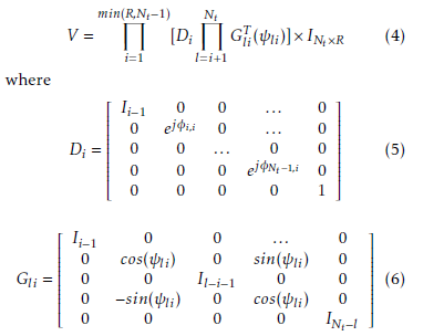 The matrix Di is an Nt ×Nt diagonal matrix, INt×R is an Nt ×R identity matrix and Gli is an Nt ×Nt Givens rotation matrix.
According to the equations (4-6), the parameters to be determined to identify the precoder matrix V are:
 where m = min(R,Nt −1).
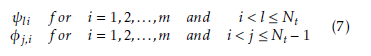
Take a 3×3 unitary matrix V as an example, it can be expressed as:
![]() The precoder matrix V can then be reconstructed through the six parameters ψ21,ψ31,ψ32,φ1,1,φ2,1 and φ2,2.
The precoder matrix V can then be reconstructed through the six parameters ψ21,ψ31,ψ32,φ1,1,φ2,1 and φ2,2.
Therefore, instead of all the elements of the matrix V , it is sufficient to considere the parameters ψli and φj,i. These parameters can vary from 0 to 2π for φ and from 0 to π/2 for ψ.
Now, ψ and φ can be quantized according to equations (9) and (10) where ψband φbrepresent the quantized angles.
 where k = 1,2,…,2nbψ −1 and nbψ the number of bits per angle ψ
 where k = 1,2,…,2nbφ −1 and nbφ the number of bits per angle φ
Finally, the receiver feeds back the quantized parameters ψbli and φbj,i to the transmitter which can recover the quantized precoder matrix Vb by using:
min(R,Nt−1) Nt
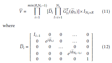 It is important to note that:
- The receiver has to feed back a precoder matrix Vb for each subcarrier.
- The quantization error Σ with Vb = V + Σ exists on each subcarrier.
Consider the equation (3) with the quantized error Σ and Vb as a precoder matrix.
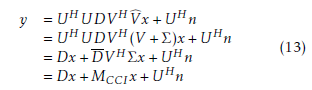 The term MCCIx = (DV HVb− Dx is the corresponding CCI caused by the quantization error. However, in telecommunication standrd, one always chooses a number of quantization bits (nbψ and nbφ) that allows the minimization of resulting CCI. This is the case of IEEE 802.11ac where nbψ = nbφ = 10.
Finally, the feedback overhead length ( in bit) noted by NFGR can be calculated using the formula NFGR = Nu ∗ nb ∗ Nt(Nt − 1) assuming that Nr = Nt, nbψ = nbφ = nb and Nu the number of used subcarriers.
3.2. Feedback overhead length analysis in IEEE 802.11ac context
The bandwidth in IEEE802.11ac has increased from a maximum of 40 MHz with the old standard up to 80 or even 160 MHz. The number of subcarriers and used one according to the bandwidth are grouped in the Table 1.
Table 1: Number of used subcarriers according to the de bandwidth in IEEE 802.11ac
| Bandwidths | N | Nu |
| 20 MHz | 64 | 52 |
| 40 MHz | 128 | 108 |
| 80 MHz | 256 | 234 |
| 160 MHz | 512 | 486 |
Table 2 contains for any MIMO configurations and bandwidth:
- the feedback overhead length when no compression is performed,
- the feedback overhead length when GR quantization is performed,
- the compression ratio achieved by GR quantization.
As we can see, the GR quantization can reach a compression ratio up to 75% for a MIMO 2 × 2 configuration. This compression ratio decreases when the number of antennas becomes large. Because of the high demand in terms of transmission throughput, the number of antennas will increase in the evolution of IEEE 802.11 standard. The next WLAN generation will undoubtedly consider the massive MIMO concept which is more and more studied for WLAN [19-20]. In this context, it is necessary to find an alternative to the GR quantization because its compression ratio, as demonstrated by the equation (14), will be around 50%:
 4. Time domain quantization
4.1. Time domain quantization principle
Consider a MIMO channel with Nt transmit antennas and Nr receive antennas. The discrete time domain channel response between the transmitting antenna i
Table 2: Feedback overhead (in bit) with and without GR quantization for any configurations (Nt × Nr and bandwidth).
|
||||||||||||||||||||||||||||||||||||||||||||||||||||||||||||||||||||||||||
and the receiving antenna j under the multipath fading environments can be expressed as:
 where L is the number of paths, hij,l and τij,l the complex time varying channel coefficient and delay of the lth path.
Note that in practical OFDM system, in order to eliminate the intersymbol interference (ISI) between consecutive OFDM symbols, the maximum multipath delay is within the cyclic prefix, of length (CP ) ie L ≤ CP . Thereby, we propose, instead of the quantized precoder matrix V for each subcarrier, to feed back the quantized time domain channel coefficients for the entire system. The main goal of this proposition is to considerably reduce the feedback overhead because in this case, the feedback is composed at most by Nt ∗ Nr ∗ CP complex coefficients. As can be seen, the number of OFDM subcarriers has no impact on the feedback overhead length. In addition, this proposed time domain quatization method can be performed jointly with the channel estimate.
4.2. Joint time domaine channel estimation and feedback quantization
In closed loop MIMO-OFDM systems, a preamble is inserted at the beginning of frames to facilitate the channel estimation. Comb-type pilot method can also be used on the rest of the frame (as in IEEE 802.11ac [2] or LTE [1]) to improve the accuracy of the channel estimation during the transmission. In this paper, we focus on time domain channel estimation (TD-CE). This technique is known to provide very good results by significantly reducing the noise on the estimated channel coefficients [21][22].
Firstly, without using any knowledge of the statistics on the channels, least square (LS) channel estimation can be performed at the receiver side using the demodulated pilots signal and the known pilots symbol in the frequency domain for each subcarrier.
Next assuming that Hij,k is the discrete LS estimated channel response on subcarriers k between the ith transmit antenna and the jth receive antenna, the CSI can be converted into the time domain by the inverse discrete fourier transform (IDFT) algorithm as:
 where Ns is the number of subcarriers and n = 1,…,Ns.
Note that the LS method is widely used due to its simplicity and minimum requirements for the knowledge of channel statistics . However, the LS estimator does not consider the noise effect. That is why its performance is often degraded by the noise. By taking into account the equation (15) and the fact that L ≤ CP , the time domain samples hij(n) from ((16)) can be divided into two parts:
- the first CP samples in which are the paths of the channel,
- the other samples which are only composed by noise.
A smothing process which keeps only the first CP samples by eliminating the other one can considerably improve the accurate of the estimated channel [21].
However, it is possible to estimate a mean of the noise
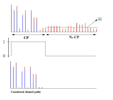 Figure 1: Mean Noise
This proposed process is illustrated in the figure 1. the metric m estimated from the noise samples allows to keep only the channel paths which are among the first CP samples. As can be seen, all samples below the m were eliminated.
Now, the receiver have to do the two following actions:
- Perform a DFT of size Ns by considering only the remaining samples hij(n). The resulting estimated channel frequency response is then more accurate than the LS one.
- Perform the feedback of the remaining samples hij(n). To achieve this goal, each of the remaining samples hij(n) whose number is lower than CP is expressed as:
![]() where n ≤ CP , ψij,n and φij,n angles parameters can vary from 0 to π/2 and 0 to 2π respectively.
where n ≤ CP , ψij,n and φij,n angles parameters can vary from 0 to π/2 and 0 to 2π respectively.
After that, ψij,n and φij,n is quantized and fed back to the transmitter according to equations
(9) and (10) where ψbij,n and φbij,n represent the quantized angles parameters.
Thus, the feedback overhead length ( in bit) noted by NFT D can be calculated using the formula NFT D = Nrs ∗2∗nb ∗Nt2 assuming that Nr = Nt, nbψ = nbφ = nb and Nrs the number of remaining samples.
Thanks to this feedback, the transmitter can reconstitute the accurate estimated channel. Thereby, the MIMO channel response is available both at the reciever and the transmitter side. Finally, transmitter and reciever perform SVD decomposition which allows it to respectively have the pre-coder and the post-coder.
5. Performance comparison in IEEE 802.11ac context
In this section, we compare the Givens rotation quantization GR-Q and the proposed time domain quantization TD-Q one in terms of feedback overhead and BER performance in IEEE 802.11ac context [2]. Note that the bandwidth in IEEE802.11ac has increased from a maximum of 40 MHz with the old standard up to 80 or even 160 MHz. For each bandwidth, the cyclic prefix length (CP ) is equal to a quarter of the number of subcarriers (in Table 1). We consider in the similations
MIMO 2×2, 3×3, 4×4, 6×6 and 8×8 with 4−QAM and 64−QAM modulations.
In the sequel, all simulations are performed using the ITU Channel Model for Outdoor to Indoor and Pedestrian Test Environment. Since the delay spread can vary significantly, the ITU recommendation specifies two different delay spreads for each test environment: low delay spread (channel model A), and medium delay spread (channel model B). The parameters of these channel’s model are grouped in Table 3. In this paper we focus on the channel model B.
5.1. feedback overhead comparison
Figures 2 to 6 show the evolution of the total number of feedback complex coefficients of the proposed time domain quantization according to the signal to noise ratio (SNR) for MIMO 2×2, 3×3, 4×4, 6×6 and 8×8 configurations. For each MIMO configuration, simulations are performed for the 4 existing bandwidth of the IEEE 802.11 ac standard (20 MHz,40 MHz,80 MHz and 160 MHz). Note that the total number of feedback complex coefficients represents the sum of all the remaining samples and it can be calculated by Nrs ∗Nt2 assuming that Nr = Nt.
As can be seen from these figures:
- whatever the MIMO configuration, the total number of feedback complex coefficients increases according to the bandwidth and the number of antennas.
- whatever the SNR, the plotted cumulative distribution function (CDF) shows that it is statistically possible for each MIMO configuration and bandwidth to know the maximum value of the total number of feedback complex coefficients. Following this study the total number of feedback complex coefficients for any configurations (Nt ×Nr and bandwidth) in IEEE 802.11ac ontext are grouped in the table 4.
Therefore, according to equation (17) the feedback overhead length of the proposed time domaine quatization ( in bit) noted by NFT D can be calculated using NFT D = Nrs ∗2∗nb ∗Nt2 and the number of remaining samples Nrs in the Table 4.
Except for MIMO 2 × 2 configuration and bandwidth 20MHz, the feedback overhead of the proposed time domain quantization is much shorter than that of the Givens Rotation quantization. The compression ratio of the proposed time domain quantization compared to Givens Rotation quantization can be up to almost 70%.
The most important to note here is the fact that unlike the Givens Rotation quantization for which the compression ratio decreases when the number of antennas becomes large (see section 3.2), the proposed time domain compression becomes more efficient. This last remark makes the proposed time domain compression very interesting for the next WLAN generation which will undoubtedly consider the massive MIMO concept which is more and more studied for WLAN
[19-20].
Table 3: ITU Channel Model for Outdoor to Indoor and Pedestrian Test Environment.
| Tap | Channel A | Channel B | ||
| Relative delay(ns) | Average power (dB) | Relative delay(ns) | Average power (dB) | |
| 1 | 0 | 0 | 0 | 0 |
| 2 | 110 | −9.7 | 220 | −0.9 |
| 3 | 190 | −19.2 | 800 | −4.9 |
| 4 | 410 | −22.8 | 1200 | −8 |
| 5 | 2300 | −7.8 | ||
| 6 | 3700 | −23.9 | ||
cording to the Signal to Noise ratio and Bandwidth for (BER) performance. The considered simulation param-
MIMO 3×3 configutation eters are listed in Table 6.
Table 5: Feedback overhead (in bit) comparison between Givens Rotation quantization and the proposed time domain quatization for any configurations (Nt ×Nr and bandwidth).
| MIMO configuration | feedback overhead NFGR for Givens Rotation quantization | feedback overhead NFT R for the proposed time domain quatization | Ratio
min |
max | ||||||
| 20 MHz | 40 MHz | 80 MHz | 160 MHz | 20 MHz | 40 MHz | 80 MHz | 160 MHz | |||
| 2×2 | 1040 | 2160 | 4680 | 9720 | 1100 | 1800 | 3220 | 5860 | −0.5% | 39.7% |
| 3×3 | 3120 | 6480 | 14042 | 29160 | 2220 | 3840 | 6680 | 12260 | 28.8% | 58% |
| 4×4 | 6240 | 12960 | 28080 | 58320 | 3820 | 6460 | 11640 | 21380 | 38.7% | 63.3% |
| 6×6 | 15600 | 32400 | 70200 | 145800 | 8300 | 14060 | 25080 | 46740 | 46.8% | 68% |
| 8×8 | 29120 | 60480 | 131040 | 271410 | 14360 | 24300 | 44100 | 82120 | 50.6% | 69.7% |
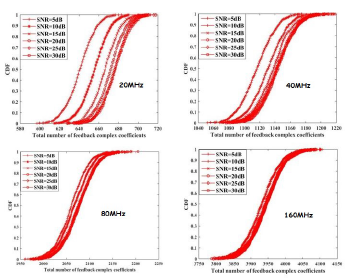 Figure 6: The Cumulative Distribution Function of the total number of feedback complex coefficients according to the Signal to Noise ratio and Bandwidth for MIMO 8×8 configutation
Table 6: Simulation Parameters
| Channel Model | ITU Channel Model |
| Bandwidth | 40MHz |
| Number of FFT points (N) | 128 |
| Number used subcarriers | 108 |
| Number of bits per angle | 10 |
| cyclic prefix | Long ie 32 samples |
| Number of Nt ×Nr antennas | 2×2 and 4×4 |
| Modulation | QPSK and 64-QAM |
| FEC | Convolutional |
| Coding Rate | 1/2 |
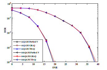 Figure 7: BER performance for perfect beamforming
(Perfect V), beamforming with GR-Q and beamforming with the prposed time domain quantization (TD-Q) in MIMO 2×2 context. The ITU Channel Model is considered for simulations.
The BER performance is shown in Figures 7 and 8 for 4−QAM and 64−QAM in MIMO 2×2 and MIMO
4×4 context respectively. The number of bits per angle feedback is taken to 10. It can be seen that the proposed TD-Q presents the same performance, for all considered configurations in these simulations, than the GR-Q which is adopted in IEEE 802.11ac standard. As considered in the 802.11ac standard, the simulations confirm that 10 bits per angle feedback minimizes the quantization error and allows the quantized beamforming (GR-Q and TD-Q) to have the same performance than the perfect one.
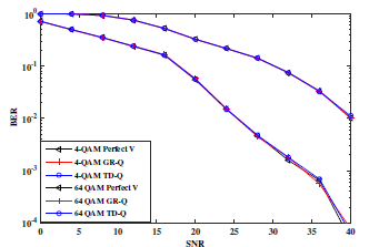 Figure 8: BER performance for perfect beamforming
(Perfect V), beamforming with GR-Q and beamforming with the prposed time domain quantization (TD-Q) in MIMO 4×4 context. The ITU Channel Model is considered for simulations.
6. Conclusion
The proposed TD-Q requires less amount of feedback than the GR-Q one in IEEE 802.11ac TxBF mode. In addition, simulations in 802.11ac context with standard TGn channel model show that the TD-Q beamforming allows to have the same performance than the adopted GR-Q. The highlight of this proposal is that the proposed TD-Q can be considered as a credible alternative to the GR-Q for the IEEE 802.11ac evolution. The proposed quantization technic is not only for WLAN systems. It can be adapted for all SISO or MIMO system using closed loop beamforming.
- Cui, H. Wang, P. Hu, X. Tao, P.Zhang, J. Hamalainen and L. Xia, “Evolution of limited feedback CoMP systems from 4G to 5G ” IEEE vehicular technologie magazine, 9(3), 94–103, 2014. DOI: 10.1109/MVT.2014.2334451
- “IEEE P802.11ac/D0.2” IEEE standard Draft, 2011.
- “Mobile WiMAX Part II: A Comparative Analysis” IWiMAX Forum, 2006
- Wang, Y. Cao and L. Zheng, “Efficient Two-Stage Discrete Bit-Loading Algorithms for OFDMSystems” IEEE Trans. on Vehicular Technology, 59(7), 3407–3416, 2010. DOI: 10.1109/TVT.2010.2052937
- Ramji, B. Ramkumar and M. S. Manikandan “Resource and subcarriers allocation for OFDMA based wireless distributed computing system” IEEE Intern Adv Comp. Conf. 2014. DOI: 10.1109/IAdCC.2014.6779345
- Goldsmith, S. A. Jafar, A. Jindal and S. Vishwanath “ACapacity limits of MIMO Channels” IEEE J. Select. Areas Commun 21, 684-702, 2003.
- Kim, Y. Jung, J. Park and J. Kim “Adaptative CSI Feedback Scheme to maximize the throughput in IEEE 802.11ac system,” IEEE ISCE 1-2, Jeju, Korea, June 2014.
- Mbaye, M. diallo and M. Mboup“LU based Beamforming schemes for MIMO systems” IEEE Trans. on Vehicular Technology, 66(3), 1-9, 2016 DOI: 10.1109/TVT.2016.2573046.
- Inoue and R. W. Heath Jr“Kerdock codes for limited feedback precoded MIMO systems” IEEE Transactions on Signal Processing, 57(9), 37113716, 2009.
- C. Roh and B. D. Rao“Design and analysis of MIMO spatial multiplexing systems with quantized feedback” IEEE Transactions on Signal Processing, 54(8), 28742886, 2006.
- J. Love and R. W. Heath Jr“Limited feedback unitary precoding for spatial multiplexing systems” IEEE Transactions on Information Theory, 51(8), 29672976, 2005.
- Schober, R. Wichman, and T. Koivisto“MIMO adaptive codebook for closely spaced antenna arrays” European Signal Processing Conference, 1-5, 2011.
- J. Ryan, I. V. L. Clarkson, I. B. Collings, D. Guo, and M. L. Honig“QAM codebooks for low-complexity limited feedback MIMO beamforming” IEEE International Conference on Communications, 41624167, 2007.
- LTE Physical layer procedures “Evolved Universal Terrestrial Radio Access (E-UTRA)” 3GPP TS 36.213 version 13.4.0 Release 13, 2017.
- Berardinelli and T. B. Sorensen and P. Mogensen and K. Pajukoski “SVD-Based vs. Release 8 Codebooks for Single User MIMO LTE-A Uplink” IEEE 71st Vehicular Technology Conference, 1-5, 2010, DOI: 10.1109/VETECS.2010.5493709.
- Zheng Jiang; Bin Han; Liang Lin; Peng Chen; Fengyi Yang; Qi Bi “On compressive CSI feedback beamforming scheme for FDD massive MIMO” IEEE International Conference on Communications in China, 1-5, 2016.
- Yuen, S. Sun, M. Ho and Z. Zhang “Beamforming matrix quantization with variable feedback rate” EURASIP journal on wireless communications and networking, 2012.
- Kim and C. Aldana“Efficient feedback of the channel information for closedloop beamforming in WLAN” IEEE VTCspring, pp. 2227-2230, Melbourne, 2006.
- Morino, T. Hiraguri, H. Yoshino and K. Nishimori“Proposal of overhead-less access control scheme for multi-beam massive MIMO transmission in WLAN systems” Med-Hoc-Net, pp. 1-5, Budva, 2017.
- Lee, K. J. Choi and K. S. Kim“Massive MIMO full-duplex for high-efficiency next generation WLAN systems” International Conference on Information and Communication Technology Convergence, pp. 1152-1154, Jeju, 2016.
- Moussa Diallo; Laurent Boher; Rodrigue Rabineau; Laurent Cariou; Maryline Helard “Transform domain channel estimation with null subcarriers for MIMO-OFDM systems” IEEE International Symposium onWireless Communication Systemse, pp. 209-213, Reykjavik, 2008.
- Zhi Zheng, Caiyong Hao and Xuemin Yang“Least squares channel estimation with noise suppression for OFDM systems” IEEE ELECTRONICS LETTERS, Vol. 52 No. 1, pp. 3739, 2016.