Mission-Critical Systems Design Framework
 , Panagiotis Oikonomidis 1, Periklis Charchalakis 2, Elias Stipidis 3
Adv. Sci. Technol. Eng. Syst. J. 3(2), 128–137 (2018);
 DOI: 10.25046/aj030215
Safety-critical systems are well documented and standardized (e.g. IEC 61508, RTCA DO-178B) within system design cycles. However in Defence and Security, systems that are critical to the success of a Mission are not defined within the literature nor are there any guidelines in defining criticality in their design or operational capabilities. When it comes to Vetronics (Vehicle Electronics), a mission-critical system, is a system with much complexity and mixed criticality levels that is a part of the overall platform (military vehicle) offering integrated system capabilities. In this paper, a framework is presented, providing guidelines in designing efficiently and effectively mission-critical systems considering principles of Interoperable Open Architectures (IOA), mission-critical integrity levels and following new standardization activities such as NATO Generic Vehicle Architecture (NGVA). A Defensive Aid Suite (DAS) system is used as a case study to illustrate how this framework can be exploited. The indention of this extension is to provide an approach to precisely estimate threats in order to de-risk missions in the very early stages.
1. Introduction
Modern military vehicles rely on mission-critical systems that enhance and guarantee successful mission capabilities. Currently, these mission-critical systems come as black boxes that are installed and maintained by the same manufacturer through the vehicle’s life-cycle. These black boxes are built on proprietary technology that only the manufacturer has access to, thus limiting the choices of maintenance and upgrades. Furthermore, existing mission-critical systems are limited to communicating with other on-board systems resulting to a vehicle having multiple instances of the same equipment (e.g. GPS sensor). This presents a number of issues including having network complexity and reduced flexibility in vehicle systems configuration depending on operational requirements.
For this reason, there is a need for an innovative architecture approach that allows components from different manufacturers to be integrated, paying particular attention to the system’s mission, safety, and security. When building a mission-critical system, the system designer should have the freedom to choose components that fit appropriately to the intended use as well as enable integration to any legacy mission-critical system or sensors/actuators that exist on-board the vehicle.
In this study, a thorough investigation is conducted offering a new open modular architectural approach on mission-critical systems including a case study on Defensive Aid Suites (DAS), aided to extract the necessary technical and functional requirements directly related to the system. This presented an opportunity to research a conceptual approach to the bespoke system whereby a constructive framework could be established with firm recommendations on a high level (abstracted) design so that a target platform can be equipped with a tailored mission-critical system to meet its specific requirements.
The novel mission-critical system architecture for military platforms adopts an open and modular design approach offering flexibility in configuration, upgradability, and integration. This enables a better operational and functional understanding of the mission-critical system, increasing integrated survivability capabilities [1].
Following the presented framework of this work, qualitative and quantitative results are extracted in order to provide mission functional concepts based on mission-critical systems and threats. Additionally from the results, an early de-risking estimation can be observed, that could be beneficial for stakeholders, systems engineers and architects to decide the appropriate elements for designing mission-critical systems in the very early stages of the overall system’s life-cycle. The rest of the paper is structured as shown below:
- Section 2 presents some representative key questions that offer the direction of designing mission-critical systems.
- Sections 3 and 4 provides a definition for mission-critical systems in line with standardisation activities around military vehicle architecture design approach.
- Section 5 offers the Generic Architecture Framework.
- Section 6 identifies some key considerations on safety and security in aligning and defining mission criticality levels.
- Section 7 provides an approach of calculating threats using numerical values and mathematical equations.
- Sections 8, 9, 10 and 11 present a case study on how the framework can be used to define a DAS Architecture including qualitative and quantitative results.
- Section 12 concludes the paper with some indication of next steps to this research.
This paper is an extension of work originally presented in International Conference on Military Technologies (ICMT) 2017 [2].
2. Key Questions
2.1. Modularity and Openness
What approaches are needed for a mission-critical system to be feasible and extract advantages such as modularity and openness?
2.2. Construction, Maintenance and Safety Certification
What are the benefits of using modules sharing specific functionalities on a mission-critical system and how efficient and effective can become?
2.3. Alongside benefits from the framework
How the framework’s modularity extracts through the mission-critical system development benefits such as safety cases and certifications?
2.4. Low-cost tools
What are the necessary tools needed to accomplish a rapid prototyping testing and permitting software functionality and operation of a mission-critical system using low-cost components?
2.5. Migration of low cost to a safety-critical performance verification testbed
How to achieve a transition from a low-cost functional testbed to a more elaborated safety-critical performance verification testbed?
3. Mission-Critical Systems
In general, the mission is the formal summary of the aims and values of an activity. The activity can be achieved with specific mission-critical elements. Those mission-critical elements are defined as vital to the functioning of an activity. Meaning that, a successful mission can be achieved when only the right mission-critical elements are applied. There are two attributes that make the specific mission-critical elements to be applied and to be right.
First, is usually when there is maturity in the applied mission-critical elements. The maturity must reach into a level that is satisfactory in each of the involved disciplines. When this level is reached, the expected outcome is sufficient and hence, the mission can be considered successful.
The second attribute is when enough knowledge is accumulated to allow for the prediction of a mission outcome to be more accurate. To achieve this, consideration needs to be given to all possible factors involved on the specific mission. Those factors are usually known or unknown and could be anything related to the mission. The knowledge can be gained when those factors are asked and answered using three main engineering questions; “What”, “Why” and “How”. Once these answers are mature enough and understandable the mission-critical elements can be referred to as vital and therefore, provide success to the mission.
Today, the technology has been developed in such a way that many missions could be successfully completed with the aid of systems. Those systems are referred to as mission-critical systems. A general definition of a mission-critical system is [3]:
“A system that is essential to the survival of a service, and whose failure or interruption significantly impacts the mission”.
A mission-critical system for a typical land military vehicle is:
“A system that is essential to complete the mission successfully”.
A mission-critical system in land military platform is composed of many discrete Vetronics (vehicle electronics) sub-systems and components including sensors, actuators, effectors, radars and processing resources. Each of these sub-systems may contain further sub-systems and components including mechanical parts.
In Vetronics the mission can be designed, described and/or accomplished either in simple or complex terms. This differentiation resulted from the characteristics that a Vetronics system has. A simple mission for a Vetronics system is when not many factors are involved. It is also simple, when a clear and an easy step-by-step procedure is provided. For instance, a mission-critical system has to transmit data from node A to node B. That can be described as a simple mission since there is only one task to be completed and if the right mission-critical elements are used.
However, in Vetronics, for a data to be transmitted from one node to another in reality it is more complicated than the previous example. What makes the mission more complicated in Vetronics mission-critical systems is when a number of multiple disciplines, such as safety, security and survivability, are involved to achieve the mission. A more desirable, refined and detailed mission procedure is required.
Assume each of the aforementioned disciplines require to complete a specific goal on the same mission. The safety prioritises the safety of people and environment; the security prioritises the protection of data from various threats; and survivability prioritise the whole mission envelop. This makes the mission more difficult to accomplish if there is neither enough maturity nor confidence on the applied mission-critical elements.
In conclusion, “mission in military applications cannot be specified or narrowed down into a single element that easily”. Therefore, an innovative unified framework is required to define and guide Mission-Critical Systems development so as to enhance mission success.
4. IOA International Activities
Today within a modern military platform, land, naval and air force, have adapted the principles of the Interoperable Open Architecture (IOA) in their system design to speed up acquisition and upgrading alongside with reducing life-cycle costs through data modelling. Below a selection of significant activities in the area of architectures and standardisation with IOA is presented.
4.1. Generic Vehicle Architecture (GVA)
The Generic Vehicle Architecture is an approach taken by the UK Ministry of Defence (MOD) to the design of electronic and power architectures for military vehicles. The approach is based on establishing system engineering principles to define a generic architecture that requires open implementation standards, Def-Stan 23-009, to support cost-effective integration of sub-systems on land platforms, electronically, electrically and physically. Any equipment shall be integrated with the GVA military land platforms must be designed in the Land Data Model (LDM) which is a (sub)-system standardisation process [4].
4.2. NATO Generic Vehicle Architecture (NGVA)
The NGVA is an approach to ensure interoperability among military land vehicles equipment. The NGVA follows a similar line to the GVA, incorporating a new method of verification and validation and by maturing the NGVA Data Model concepts, focus and implementation can be achieved [5], [6].
4.3. Future Airborne Capability Environment (FACE)
The FACE approach is an aviation US government-industry software standard and business strategy for acquisition of affordable software systems that promotes innovation and rapid integration of portable capabilities across global defence programs. The main objective of this approach is to make military operations more robust, interoperable and secure using open standards [7].
4.4. Vehicle Integration for C4ISR/EW Interoperability (VICTORY)
VICTORY is a US army vehicle’s open standard for physical and logical interfaces between systems and C4ISR/EW components. The VICTORY architecture targets to provide a clear picture between to the users and the developers. Throughout the usage of an open architecture, the platforms can accept upgrades without a significant impact on the design.
5. Generic Architecture Approach
Model Driven Architecture (MDA) is an approach that is used in the system engineering domain to improve product development and delivery. The approach was initially launched in 2001 by the Object Management Group (OMG) to support the model-driven engineering of software systems. The main objective of the MDA is to provide a set of specifications of system’s functionality and behaviour expressed in models. Instead of writing the code manually, the MDA approach with the help of a data modelling tool it is possible to regenerate automatically an application code. Additionally, this approach reduces implementation and integration risks when an activity is designed.
In Figure 1 an illustration of the MDA process is presented. Initially, the system requirements can be defined and specified into a Platform Independent Model (PIM) model. Using a specific standard and specification, the model can be constructed in a formal way such as the Unified Modelling Language (UML). The objective of the PIM model is to specify data, operations, functions and modes of a system, independent of the platform in which it may be integrated. In order to organise and standardise the data as well as facilitate a long-term improvement in interoperability and upgradability within the model, a data model is essential. A Platform Specific Model (PSM) model contains elements of a specific software platform. It can be generated from the PIM model either manually or automatically if appropriate tools are used. The PSM embeds the chosen software architecture strategies which refine the PIM model based on specifications. The Platform Specific Implementation (PSI) embeds the chosen middleware technology and explains the usage of a specific platform.
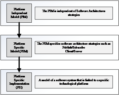 Figure 1. Model Driven Architecture Approach.
Each electronic device is developed to satisfy one or more specific task(s) thus, the devices can only generate or receive a set of specific data for their operation. Therefore, when these devices are integrated into an IOA architecture, the broadcasted data cannot be ensured if is critical or not. For instance, the real-time level cannot be defined just by the device itself but is needed to be declared from the designers. Below there is a brief explanation of the real-time levels.
Real-Time Level – In any electronic architecture there is a set of data or information it might be critical or noncritical. Real-time can enable non, soft and hard responsiveness depending on what level, prioritisation, and importance the data is designed for. In Vetronics different real-time levels are applied for satisfying different level processes or events. The definitions of real-time levels are:
- Non-Real-Time (NRT) – Best Effort Service with no time constraints.
- Soft Real-Time (SRT) – Relaxed time (latency) requirements.
- Hard Real-Time (HRT) – Fixed time requirements. [8]
Due to the different critical level of data in Vetronics, this paper proposes a novel framework to support the developers to design and decide whether the data is critical or noncritical. With the aid of a flowchart, Figure 2 demonstrates a modular framework that is aimed to accurately design a data for a mission-critical system. The designer must firstly define the data attribute and if is already existing on the model. When the data attribute is declared, the designer must decide in what level of real-time responsiveness the data is belonging to. The different levels the data can take are the Hard, Soft, and Non-Real-Time. This can be useful for the developers to choose the appropriate network communication technology. Next, the designer must declare the criticality level of the data by choosing between Mission, Safety, and Security Critical levels. The critical levels shown in the diagram are the most commonly used levels used in the Vetronics systems. The user has the freedom to add/remove other critical levels such as survivability or business critical.
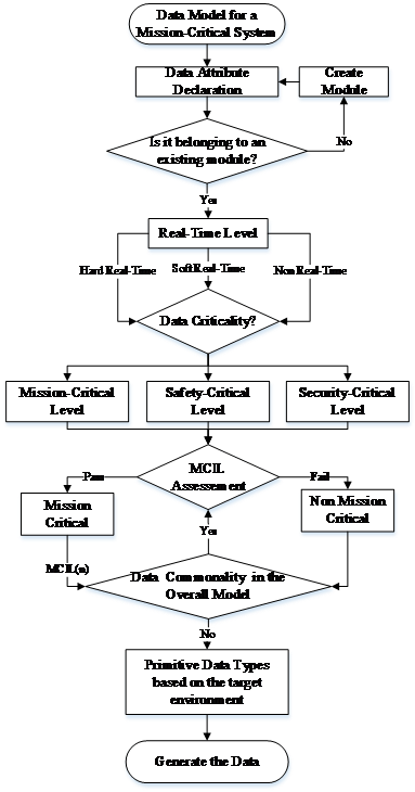 Figure 2. Mission-Critical Modelling Framework.
The next step is an assessment that is applied for the mission planning and goals based on risk assessments, a detailed explanation will be discussed in Sections 10 and 11. If the data fails the assessment is considered as non-mission-critical and if the data meets the requirements then is considered as mission-critical. In the mission-critical block, the data will be labelled with the Mission-Critical Integrity Level (MCIL). To ensure that the model is not polluted with data having similar attributes, a data commonality assessment is provided for addressing that issue. Finally, the data must have its own data type and must be checked whether the data type can be supported or not by the targeted programming language.
In a communication network, there are multiple connection points that are able to receive, store and send data across. These connection points are known as network nodes. Figure 3 depicts a generic network node which is divided into three elements, communication, processing, and application. The application element, is a computer program designed to perform a group of coordinated functions, tasks or activities for the benefit of the end user. The processing in a networked node, is a combination of machines, people, and processes that for a set of inputs produces a defined set of outputs. And the communication is the communication endpoint. The transmission of data from one computer to another is achieved by the communication device using various communication technologies [9].
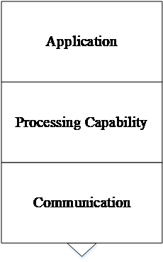 Figure 3. Network Node.
In the military vehicles, multiple (sub)-systems are integrated on a single platform. In a mission-critical system the most commonly used network nodes are sensors, actuators, effectors, processing nodes and so on. All the network nodes are interacting together through a virtual networking, as shown in Figure 4. A virtual network is capable of controlling one or more nodes over a logical or virtual networks that are decoupled from the underlying network hardware. This is used to ensure that the network nodes can efficiently integrate and perform on a single network. Common data sharing technologies used for military applications are the Data Distribution Service (DDS) and the Message Queuing Telemetry Transport (MQTT). The gateway block is integrated to support system legacy and allow different existing on-board systems to provide and receive services.
6. The need of Safety and Security
In land military platforms, there are other existing critical systems. These critical systems are for the safety and for the security of the platform and the crew. Safety critical systems are the systems whose failure may endanger human life, economics or the environment. Examples of safety critical systems in military vehicles are the vehicle’s steering and fire control. Security critical systems deal with the integrity and loss of sensitive data through theft or accidental loss [10].
 Figure 4. Virtual Network.
Safety and security critical systems can be used to extract logical capabilities, in which they can be mapped and used as the essentials of a successful mission-critical system. Considering safety and security capabilities on the development of a mission-critical system, it is possible to achieve a complete integrated survivability system [11]. It is vital to increase the dimensions and properties of safety and security in a mission-critical system to address issues such as intrusion detection, component fault/failure detection system behaviour, and restoring essential services in case of a security attack [12].
The developer must specify and approve the criticality level of each data. This can be varied depending on the application and technical specification related to user and system requirements. Although it is possible to declare and assess the data’s mission-critical level using the Tables 1-4. The tables are essential to achieving a successful mission-critical system in which the mission goals are based on risk assessments. Risk assessments should be set and then that, the rigour of management and processes should be appropriate to meeting them.
Assume a civilian vehicle used for a military application; when the vehicle’s passenger opens the vehicle’s door some interior lights are switched on. The interior lights are designed to provide luminosity in the vehicle at night or in dark environments. During the day or at bright environments the light does not significantly impact any process thus the related data for the light can be categorised as negligible or MCIL4. During the night the light may provide luminosity to the passengers but it also indicates the vehicle’s location. If the vehicle is used for a mission during night, it is likely the mission will fail, thus the corresponding data, for the light, can be categorised to as catastrophic or MCIL1. However, any data must be filtered and tested through the risk assessments before is integrated into the platform. Furthermore, the framework requires, that hazard and risk assessments be executed for the analysis of the likelihood of occurrence, consequences and detection levels provided by the tables below.
Table 1 Categories of likelihood of failure occurrence
| Category | Definition | Range
(Mission Failure) |
| Frequent | Many times in missions | > 10-3 |
| Probable | Several time in missions | 10-3 to 10-4 |
| Occasional | Once in mission | 10-4 to 10-5 |
| Remote | Unlikely in missions | 10-5 to 10-6 |
| Improbable | Very Unlikely | 10-6 to 10-7 |
| Incredible | Cannot believe that it could occur | < 10-7 |
Table 2 Consequence categories
| Category | Definition |
| Catastrophic | Complete mission failure |
| Critical | Impacts mission but not complete failure |
| Marginal | Major mission issues |
| Negligible | Minor mission issues |
Table 3 Risk class matrix
| Likelihood | Consequence | |||
| Catastrophic | Critical | Marginal | Negligible | |
| Frequent | Class 1 | 1 | 1 | 2 |
| Probable | 1 | 1 | 2 | 3 |
| Occasional | 1 | 2 | 3 | 3 |
| Remote | 2 | 3 | 3 | 4 |
| Improbable | 3 | 3 | 4 | 4 |
| Incredible | 4 | 4 | 4 | Class 4 |
The classification of the consequences are as follow:
- Class 1: Unacceptable in any circumstance
- Class 2: Undesirable: tolerable only if risk reduction is impracticable or if the costs are grossly disproportionate to the improvement gained.
- Class 3: Tolerable if the cost of risk reduction would exceed the improvement.
- Class 4: Acceptable as it stands, though it may need to be monitored.
Once the hazard and risk assessments are identified, each of the threats should also be assigned with a detection level, as given in Table 4, in order to provide a definition in which degree a threat can be detected.
Table 4 Detection Levels
| Difficulty Level | Definition |
| No effort | Very likely to be detected |
| Very Easy | With almost no effort |
| Easy | Without great effort |
| Normal | Conforming to a standard |
| Hard | With a great deal or effort |
| Very Hard | Not likely to be detected |
Mission-critical levels, see Table 5, offers the ability to attain in regards to mission-critical system development and related to the Classification Matrix given in Table 3. Throughout risk assessments the target MCIL can be identified and thus, it can be converted as a requirement for the mission-critical system. The derived requirements can provide an efficient data model development that can be used and ensure that the mission-critical system can succeed a mission.
Table 5 Mission-Critical Levels
| Mission-Critical Integrity Level | Mission Failure Factor | Risk Classification |
| MCIL 4 | 100,000 to 10,000 | Class 4 |
| MCIL 3 | 10,000 to 1,000 | Class 3 |
| MCIL 2 | 1,000 to 100 | Class 2 |
| MCIL 1 | 100 to 10 | Class 1 |
Safety (mission) critical applications, such as in [13] and [14], are using safety standards, such as the IEC 61508 and the RTCA DO-178B, in which are oriented for people’s safety when a system is designed. The standards are intended to be a basic functional safety standard applicable to cover the safety management of electrical, electronic and programmable electronic systems throughout their lives. If the development of a mission-critical system involves human factors then the system should be considered as a safety critical system.
7. Threat Estimation
First, it is important to note that Tables 1, 2 and 4 are abbreviated as, Occurrence – O[n], Severity – SE[n], Detection – D[n] and threat estimation as T[n], with “[n]” representing a natural number [1] of each element or requirement. For example, if one threat is identified within the framework, then the threat will be assigned to as T[1]. If threat T[1] has sub-requirements, then it will be assigned to as T[1][n].
In order to evaluate or estimate the criticality of the identified threat T[n], the aforementioned tables and their elements must be assigned with numerical values, as depicted in Table 6. The idea behind the values is indicative (assumption), therefore, the maximum value of the threat T[n] can be roughly 99.9% and the lowest 0%. These values will indicate the probability of the threat affecting the mission.
Therefore, the threat level of the identified threat T[n], TL_T[n] can be calculated using the following expression,![]()
Where,
TL_T[n]: The threat level of the identified threat.
O[n]: The occurrence value of the O[n].
SE[n]: The severity value of the SE[n].
D[n]: The detection value of the D[n].
In the event of having multiple threats or sub-threats, an estimation of an overall threat must be calculated in order to predict the probability of the mission success. A representation of this is shown in Table 7.
Where,
Req_core: The core requirement.
1st Sub: The first sub_core_requirement.
n Sub: Indicated the last sub-requirement.
n: Represents the real number.
i: Represents the sequential number of sub-requirements.
An approach on how to calculate the average value of two or more requirements of the same degree is as follows, (2),
| Table 6 The Assigned Values for Calculating Threat T[n] | |||||
| Occurrence – O[n] | Occurrence (%) | Severity – SE[n] | Severity (%) | Detection – D[n] | Detection (%) |
| Frequent | 25 | Catastrophic | ≤50 | Very Hard | 25 |
| Probable | 20 | Critical | ~33.4[3.s.f] | Hard | 20 |
| Occasional | 15 | Marginal | ~16.7[3.s.f] | Normal | 15 |
| Remote | 10 | Negligible | 0 | Easy | 10 |
| Improbable | 5 | Very Easy | 5 | ||
| Incredible | 0 | No Effort | 0 | ||
Table 7 Requirement Sequence
| Req | 1st Sub | n Sub |
| Req[1][1] | Req[1]…i…[1] | |
| Req[1] | … | … |
| Req[1][n] | Req[1]…i…[n] | |
| … | … | |
| Req[n][1] | Req[n]…i…[1] | |
| Req[n] | … | … |
| Req[n][n] | Req[n]…i…[n] |
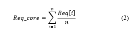 Where:
Req_core: The overall average value of the core requirement.
i: Lower limit number of requirement.
n: Upper limit number of requirement.
8. Case Study: Defensive Aid Suite (DAS) System
A most commonly used mission-critical system in the military platforms, is the Defensive Aid Suite (DAS) system. Is a survivability system, and can be used as a potential case study that addresses similar complexity issues to the aforementioned mission-critical systems and integration levels. A DAS is composed of sensors, effectors, algorithms and Human Machine Interfaces (HMI) that enhances the integrated survivability of a military vehicle. DAS also consists of different decoupling physical and logical capability networks applied for specific tasks or applications.
The DAS system can be a semi-autonomous or autonomous system that is capable of detecting, recognising and addressing threats. DAS elements are classified into two major categories Soft-Kill and Hard-Kill; other action categories are also possible where effective countermeasures can be deployed by other assets.
A Hard-Kill system engages and destroys threats. It creates an active fire zone of protection at a safe distance near the vehicle.
A Soft-Kill system is designed to avoid threats by confusing or re-directing the threats using jammers, decoys, and signature reduction measures.
An existing soft-kill DAS system from [14] has been selected for this case study, using existing DAS system components. In this DAS system various electronic components can be addressed, which are used in a Light Armed Vehicle (LAV) vehicle. A component such as the Long Range Passive Sensing (LRPS) sensor. The threat can be detected using optical systems with either Wide Field Of View (WFOV) or Narrowed Field Of View (NFOV) mounted on the platform. Each of the detected threats produces a signature identifying a potential threat that may be weapon systems such as guns and anti-tank rocket-propelled grenade launchers (i.e. M-712 and RPG-7). The detection range of the WFOV and NFOV optics are represented in Table 8. The table can be used as a message specification for a generic DAS system.
Table 8 Sensor Camera and Threats Attributes [15]
| Anti-Armour Threats | Threat, Calibre | M-712, LSAH, 155mm | RPG-7, 80mm | Gun, 20mm, APDS |
| IR WFOV | Distance, [m] | 400 | 470 | 5480 |
| IR NFOV | Distance, [m] | 3600 | 4200 | 340 |
| LI/RG Camera | Threat, [Pixels] | 1.3 | 42 x 42 | 0.8 |
| Target, [Pixels] | 25×20 | 234 x 187 | 118 x 60 | |
| Threat
Variables |
Dimensions, [m] | 0.155 dia. | 0.18 dia. | 2.1 dia. |
| Range, [m] | 14000 | 500 | 2000 | |
| Velocity, [m/s] | 255 | 255 | 815 |
9. Proposed DAS Architecture and Modules
This section presents a novel DAS system architecture that could be potentially used to satisfy the questions in Section II as presented earlier in this paper. For the system to facilitate a modular framework the Model Driven Architecture approach is used to construct modules that enable upgradability, maintainability and system legacy with technologies, devices and operational or functional capabilities. This proposed DAS architecture aims to fuse systems and software modelling and simulation capabilities, modular open system architectures and device integration techniques into a single package to enable rapid design, development, verification, certification and deployment of interoperable, platform portable and manoeuvre embedded mission criticality. The following sub-sections are classified as module models used for a DAS system and can also be applied for any mission-critical system.
9.1. Threats
Threats are all the known causes that can damage the platforms. Threats can be either external or internal; internal threats could be cyber-attacks, malfunction etc. External threats could be missiles or mines.
9.2. Sensors
Sensors module represents all the candidate sensors used for the DAS system. This module is for detecting and responding to any incoming threat from the physical environment. The specific input may be motion, heat, light or any of other environmental phenomena. The output is a signal that is converted into a format that is human readable or machine readable electronically transmitted over a network for exploitation and further processing. The Sensors module can be directly connected to the DAS Sensor Processing Module to apply the safety, security, and performance on the indented design.
9.3. DAS Sensor Processing Module (DASSPM)
The DASSPM is the module that is capable of receiving the data/information from the DAS sensor. The DASSPM converts the data into a usable format that can classify, position and eventually eliminate or avoid the detected threat. The module will be able to detect also the attributes of the candidate DAS sensor in terms of type and capability if the appropriate message specification is constructed.
The DASSPM, therefore, receives the data/information from the candidate sensor and extra qualities can be added. Developers can customise the data and modify it into the corresponding real-time environment, criticality level, and mission-critical integrity level. The DASSPM will also communicate with the DASECM.
9.4. DAS Computer Module (DASCM)
The DASCM collects and processes the information from the DASSPM, to decide the best action for each available threat. This action may require user interaction or it can be fully automated. The modular design allows the system designer to use a single or multiple DASC that may deal with the same or different types of threats at the same time, providing fault tolerant and distributed design. Then the DASC communicated with the appropriate DAS Effector Control Module (DASECM), depending on the type of action decided. When there is no DASC available, the DASECM takes responsibility for the appropriate countermeasure action.
9.5. DAS Effector Control Module (DASECM)
The DASECM is responsible for controlling the DAS effectors according to the commands received from the DASCM. This module has many commonalities in data and functionality with the DASSPM. In the case of DASC failure, the DASECM can be actioned to directly deal with the threat. Additionally, it offers configuration options for the effector to achieve modularity and dynamic configuration.
9.6. Effectors
The Effectors Module is the representation of the all the candidate effectors. This module is constructed upon the available effectors needed to be installed on the platform. Each of the candidate effectors carries specific attribute thus, the module is using message specifications common to the overall architecture.
10. Top Level of a DAS Data Model
Due to the increased number of electronic components designed from different manufacturers who use different technologies, approaches, standards and architectures, the systems integration process becomes rather complex. A suggested approach to improve the vehicle’s performance and survivability is to use, information management techniques. In this paper, the potential approach to such component’s capability acquisition is proposed by structuring a set of message specifications and develop the DAS Data Model, represented in Figure 5.
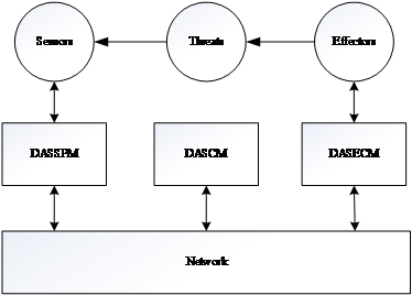 Figure 5. Top Level of DAS Architecture.
Following the proposed framework and the proposed DAS architecture and modules, the system will be able to use different battlefield scenarios, operational modes and different electronic devices from different manufacturers. With this development and the combination of the proposed approaches, the DAS Data Model will provide the different criticality levels and the different real-time environments that will be the essentials for a successful mission.
10.1. DAS PIM
Using the IBM Rational Rhapsody Developer for C++ tool, the message specification for the soft-kill DAS system sensors is represented in a UML model as shown in Figure 6. The tool is selected because it is the most commonly used for land vehicle electronic architectures, specifically in the GVA approach implementation [4]. This a PIM in which it has the ability to be redesigned when additional modifications are required during the development, or additional sensors are included in the DAS system. This PIM model is constructed using the attributes in Table 8 and with the usage of the proposed MCIL framework and DAS architecture, the mission-critical message specifications of a soft kill DAS can be created.
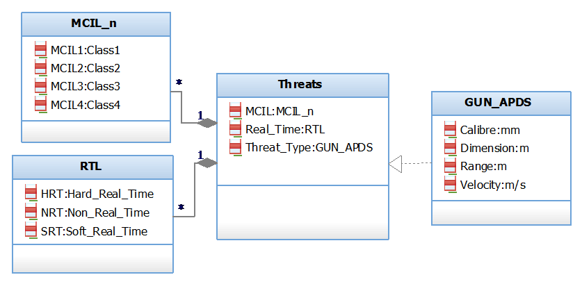 Figure 6. Threat PIM.
The message specification in Figure 6 has its own Mission-Critical Integrity Level (MCIL_n) and Real-Time (RTL) levels. The developer will have the freedom to choose between the aforementioned levels when applying the paper’s approaches. For instance, if the vehicle uses passive armour the specific threat is not lethal, therefore, the Mission-Critical Integrity level of the message can be classified as Class 4. If is a light armoured vehicle then the Mission Criticality Integrity level can be classified as Class 2. The same can be applied for the Real-Time responsiveness.
10.2. DAS PSM
Once the PIM model is designed and specified, the model can be translated into PSM for integration into a specific architecture. The middleware technologies that can be used are the Data Distribution Service (DDS) or Message Queue Telemetry Transport (MQTT). DDS is an OMG machine-to-machine middleware standard that offers scalability, real-time, Quality of Service (QoS), high performance and interoperability data exchange between data publishers and subscribers. Publish/Subscribe message patterns are used for sharing the DAS system data in order to minimise the impact of adding new sub-systems [16]. MQTT is a lightweight messaging protocol that offers bi-directional communication to nodes. Its design has been created to minimise network bandwidth that uses the messages in a reliable degree of delivery.
When each attribute in the PSM model has its own data type, it must be specified and validated from the supported primitive data types of each target environment of DDS. The message specification file is used to describe the software component’s application in order to enable communication between software components from different programming languages. However, the PSM transformation can be translated into a PSI model for the simulations and apply case studies of any mission-critical environments.
11. Qualitative and Quantitative Results
Using the example in Figure 6 (Section 10.1) and applying the threat estimation procedure discussed in Section 7, the threat can be calculated and then estimate the effect level of the mission. The example stated the following, “if the vehicle uses passive armour the specific threat (see Figure 6) is not lethal, therefore, the Mission-Critical Integrity level of the message can be classified as Class 4. For a light armoured vehicle then the Mission Criticality Integrity level can be classified as Class 2”. In this section an estimation of the effect level of the stated threat is presented using anticipated values for each element.
11.1. Case 1: Passive Armour Vehicle
Case 1: If the vehicle uses passive armour then threat is as depicted in Figure 7.
The occurrence O[1] of the potential cause can be occasional. Therefore, the occurrence selected from Tables 1 and 6 is,
Occurrence: O[1] – Occasional (15%)
Using Table 6, the O[1] is 15%.
Considering that the threat does not significantly impact the mission or the vehicle, the severity of the specified threat can be negligible. Using Tables 2 and 6,
Severity: SE[1] – Negligible (0%)
Assuming that the vehicle uses passive armour instead of active, the threat T[1] will be detected from the crew. Therefore, the detection might be considered to as hard to detect, and using Tables 4 and 6,
Detection: D[1] – Hard (20%)
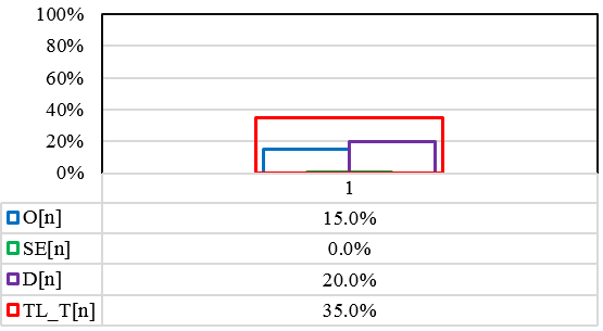 Figure 7 Case 1: T[n] Level
TL_T[1]: [(O[1]:15%)+(SE[1]:0%)+(D[1]:20%)= 35%
After the threat analysis of the specific threat for this case study, it has been identified to be 35% hazardous against the mission.
11.2. Case 2: Light Armoured Vehicle
Case 2: If the vehicle is a light armoured vehicle then the threat will be as in Figure 8. The occurrence O[1] of the potential cause can be occasional similar to the Case 1. Therefore, the occurrence selected from Tables 1 and 6 is,
Occurrence: O[1] – Occasional (15%)
Using Table 6, the O[1] is 15%.
Considering that the threat significantly impacts the mission or the vehicle then the severity of the specified threat can be catastrophic. Using the table 2 and 6,
Severity: SE[1] – Negligible (50%)
As aforementioned, the vehicle is a light armoured vehicle and assume that it has an integrated DAS system. Therefore, the threat T[1] to be detected can be categorised as easy. Using the Tables 4 and 6, detection is,
Detection: D[1] – Easy (10%)
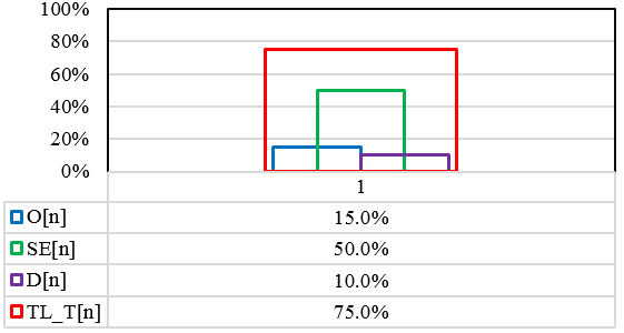 Figure 8 Case 2: T[n] Level
TL_T[1]: [(O[1]:15%)+(SE[1]:50%)+(D[1]:10%)= 75%.
The same threat as identified in Case 1 has being calculated to be 75% within this case study (2); whilst the same threat for a different mission scenario has increased in terms of threatening level. This in turn, elements that can be identified for a mission shall be re-used and analysed accordingly using this preliminary mission analysis at this early stage of a mission-critical system.
12. Conclusion and Future Work
At present there are no current development activities employed for mission-critical systems. In this paper, the importance of those activities is discussed. The objective of the proposed framework, is to enable system engineers achieve the mission development of any critical system’s life-cycle, efficiently and effectively. This is achieved through a single package, using the three following main capabilities.
Firstly, a basic functional “mission standard” that enables the mission life-cycle development in a critical system; Secondly, the ability of mission interoperability for services and functionalities between systems and sub-systems built and procured in different times; and finally, the process that can support to define and analyse the mission data requirements of various critical systems.
The paper covered only the primary mission-critical attributes of a critical system, extracting the basic functional requirements. The scope of those requirements is paying particular attention on the mission, safety and security-critical attributes.
Furthermore, the extended part of this work, proposed an approach to estimate threats and their impact on a mission so as to early de-risk missions and systems (mission-critical) whilst in their design stages.
The next step is to further develop and refine the proposed using detail low level design case studies along with measures of performance.
- Ponsard, P. Massonet, A. Rifaut and J. F. Molderez, “Early Verification and Validation of Mission Critical Systems,” Electronic Notes in Theoretical Computer Science 133, pp. 237–254, 2005
- Houliotis, P. Oikonomidis, P.Charchalakis, E. Stipidis, “An Efficient Approach to Designing Mission-Critical Systems, Case Study: Defensive Aid Suite (DAS) Systems”, 2017 International Conference on Military Technologies (ICMT), Brno, Czech Republic May 31 – June 2, pp 402-409, 2017
- Ponsard, P. Massonet, A. Rifaut and J. F. Molderez, “Early Verification and Validation of Mission Critical Systems,” Electronic Notes in Theoretical Computer Science 133, pp. 237–254, 2005
- Ciccozzi, I. Crnkovic, D. Di Ruscio, I. Malavolta, P. Pelliccione, R. Spalazzese, “Model-Driven Engineering for Mission-Critical IoT Systems.” in IEEE Software, vol. 34, no. 1, pp, 46-53, Jan.-Feb.2017
- UK Ministry of Defence (MOD), “Generic Vehicle Architecture (GVA),” 2010
- NATO, STANAG 4754, “NATO Generic Systems Architecture (NGVA) for Land Systems,” Edition 1, Ratification draft, August 2015
- Pradhan and D. Ota, “An adaptable multimodal crew assistance system for NATO generic vehicle architecture,” 2016 International Conference on Military Communications and Information Systems (ICMCIS), Brussels, pp. 1-8, 2016
- Williamson, “Future Airborne Capability Environment (FACE),”2010, from“http://www.defensedaily.com/Assets/Williamson%20Panel%204%20.pptx
- A. Brandt, S. Banachowski, C. Lin, T. Bisson, “Dynamic Integrated Scheduling of Hard Real-Time, Soft Real-Time and Non-Real-Time Processes”, Proceedings of the 24th IEEE International Real-Time Systems Symposium (RTSS’03), 2003
- M. Connor, “VSI Vetronics Standards and Guidelines”, QINETIQ/EMEA/TS/CR0702540 Issue 3, June 2009
- P. Lobo, P. Charchalakis, and E. Stipidis, “Safety and security aware framework for the development of feedback control systems,” 10th IET System Safety and Cyber-Security Conference 2015, 2015
- Deshpande, O. Obi, E. Stipidis, and P. Charchalakis, “Integrated vetronics survivability: Requirements for vetronics survivability strategies,” 6th IET International Conference on System Safety, Birmingham, 2011
- Obi, a Deshpande, E. Stipidis, and P. Charchalakis, “Intrusion Tolerant System for Integrated Vetronics Survivability Strategy,” 8th IET International Safety Conference incorporating the Cyber Security Conference, Cardiff, 2013
- Larrucea, J. Perez, and R. Obermaisser, “A Modular Safety Case for an IEC-61508 Compliant Generic COTS Processor,” IEEE International Conference on Computer and Information Technology; Ubiquitous Computing and Communications; Dependable, Autonomic and Secure Computing; Pervasive Intelligence and Computing, Liverpool, pp. 1788–1795, 2015
- Kong and H. Yan, “Comparisons and analyses between RTCA DO-178B and GJB5000A, and integration of software process control,” 2010 3rd International Conference on Advanced Computer Theory and Engineering (ICACTE), Chengdu, 2010
- [15] L. Rapanotti, “Developing soft-kill capability for light armoured vehicles through battlefield simulations,” Defence R&D Canada – Valcartier Technical Memorandum DRDC Valcartier TM 2003-276, 2007
- USA Department of Defence (DOD), “The Data Distribution Service Reducing Cost through Agile Integration”, 2011, from “http://www.twinoakscomputing.com/wp/DDS_Exec_Brief_v20l-public.pdf
No related articles were found.