Adaptive and Non Adaptive LTE Fractional Frequency Reuse Mechanisms Mobility Performance

Adv. Sci. Technol. Eng. Syst. J. 3(1), 511–520 (2018);
 DOI: 10.25046/aj030162
Mobile broadband has gained momentum with the growing demand of user data rates. Long Term Evolution (LTE) technology is the step in mobile communications evolution, developed to satisfy high data rate demand, and meet better spectral efficiency requirements. Effective radio resource management and inter cell interferences are the major challenges. Fractional Frequency Reuse (FFR) is one of the effective interference avoidance mechanisms applied to LTE networks to yield optimal throughput. In this extended paper, we propose a novel performance metric, weighted throughput on user satisfaction, and evaluate an existing adaptation process that dynamically adjusts to optimal network performance determined by FFR mechanism with mobile users. The performance of FFR mechanism with mobility model, adaptation process, and femtocell densification is evaluated and optimized for proposed metric and other metrics. Results optimized by proposed metric show comparatively higher average throughput and lower variance among user throughput.
1. Introduction
Orthogonal Frequency Multiple Access (OFDMA) offers great spectrum efficiency and flexible frequency allocation to users. However, in LTE OFDMA networks the system performance is severely hampered by the Inter-Cell Interference (ICI) due to the frequency reuse, where the cell edge users will experience high interferences from neighboring cells.
FFR is one of the interference management techniques which require minimal or no coordination among the adjacent cells. The basic mechanism of FFR is to partition the macrocell area into spatial regions and each sub-region is assigned different frequency sub-bands for users. In [1, 2], the user satisfaction metric introduced by the authors is evaluated for users’ mobility and the performance is compared with other reuse schemes. The authors propose a dynamic mechanism that selects the optimal FFR scheme based on the user satisfaction metric. The proposed mechanism is evaluated through several simulation scenarios that incorporate users’ mobility and its selected FFR scheme is compared with other frequency reuse schemes in order to highlight its performance. The research is further enhanced in [3] where cell edge reuse factor is set to 1.5 and results are generated to determine the optimal inner radius and frequency allocation. In [4, 5], a performance study is carried out, where FFR partitions each cell into two regions; inner region and outer region, and allocates different frequency band to each region based on reuse factor. In [6], a frequency reuse technique is proposed which aims at maximizing throughput via combinations of inner cell radius and frequency allocation to the macrocell. In this work, the authors study the interference mitigation techniques in femtocell/macrocell networks and proposed a FFR mechanism that leads to increased overall system performance. Work in [7] proposes a mechanism that selects the optimal FFR scheme based on the user throughput and user satisfaction. In [8, 9], authors present a FFR optimization scheme based on capacity density (bit/s/m2), which show better performance compared to conventional Reuse-1 and Reuse-3 schemes. The authors formulate an optimization problem and solve it by simulation. Graph theory and similar optimization techniques are presented in [10], a graph-based framework for dynamic FFR in multicell OFDMA networks is proposed in this work. The proposed scheme enhances the conventional FFR by enabling adaptive spectral sharing per cell load conditions. Such adaptation has significant benefits in a practical environment, where traffic load in different cells may be asymmetric and time-varying. Work in [11, 12] provides analysis of the inter cell interference coordination problem in multi-cell OFDMA systems. In order to reduce the interference without losing much frequency resources in each cell, cell users are partitioned into two classes, interior and exterior users. Results determine the optimal configuration of the interior and exterior regions’ dimensions as well as the optimal frequency reuse factor.
Authors in [13] use two-stage heuristic approach to find optimal frequency partitioning. The authors intend to propose the FFR scheme by introducing the concept of normalized Spectral Efficiency (nSE). With the optimal Frequency Reuse Factor (FRF), the FFR scheme can maximize the system SE with throughput improvement of cell-edge users. To solve the problem, they divide it into two sub-problems. However, this scheme is asymptotically optimal with the assumption of the uniform distributions of signal and interference in sectors. The simulation results demonstrate the gain of the system SE is about 3% by proposed FFR scheme. The goal in work in [14] is to improve the cell edge throughput as well as the average cell throughput, compared to a network with frequency reuse factor 1. The cell capacity under those reuse schemes is estimated and compared. To attain both high spectral efficiency and good coverage within sectors/beams, a scheme based on coordinated scheduling between sectors of the same site, and the employment of frequency reuse factor above 1 only in outer parts of the sector, is proposed and evaluated. The resulting sector throughput increases with the number of active users. When terminals have one antenna and channels are Rayleigh fading, it results in a sector payload capacity between 1.2 (one user) and 2.1 bits/s/Hz/sector (for 30 users) in an interference-limited environment [15]. In [16], the authors review some of the recent advances in ICI research and discuss the assumptions, advantages, and limitations of the proposed mechanisms. They propose a scheduling algorithm to schedule users based on channel quality and quality of service (QoS) metrics.
Authors in [17] investigate an OFDMA radio resource control (RRC) scheme, where RRC control is exercised at both RNC and base stations. In [18], the authors present an analytical solution to carry out performance study of various frequency reuse schemes in an OFDMA based cellular network. Results of performance study show that results obtained through analytical method are in conformity with those obtained through simulations. In [19], the authors analyze the FFR scheme and propose a dynamic FFR mechanism that selects the optimal frequency allocation based on the cell total throughput and user satisfaction.
Extensive work is done to optimize network performance of FFR mechanism [20]. FFR and exploitation of the channel state information at the transmitter (CSIT) are effective approaches to improving the spectrum efficiency of the outer coverage region. When channels vary within a physical transmission frame, the above improvement is substantially suppressed. To remedy this, work in [21] develops new FFR patterns for OFDMA systems with frequency or time division duplexing (FDD/TDD) in time-varying channels. Simulation results show significant performance gains of the proposed schemes over the existing ones. A semi-centralized joint cell muting and user scheduling scheme for interference coordination in a multi-cell network is proposed under two different temporal fairness criteria. The authors in [22] propose a general pattern set construction algorithm in this paper. Numerical results are provided to validate the effectiveness of the proposed scheme for both criteria. The impact of choice of the cell muting pattern set is also studied through numerical examples for various cellular topologies. Densely deployed cellular wireless networks, which employ small cell technology, are being widely implemented. Authors in [23, 24] aim to maximize the system’s throughput through the employment of FFR schemes. The authors derive the optimal configuration of the FFR scheme and evaluate the systems performance behavior under absolute and proportional fairness requirements. Table 1 shows comparison between previous published work and paper contributions.
Table 1: Comparison
| Parameter | Previous | Current |
| Work | Paper | |
| Throughput variance | High | Low |
| Femtocells adaptation | Minimal | High |
This paper evaluates the performance of the sectorized FFR mechanism with five metrics; four existing and one proposed, which determine the values for inner region radius and frequency allocation for optimal results. For a specific mobility model, an adaptation process is applied to the FFR mechanism optimized for each of the five metrics and its performance is evaluated. Results are also generated and evaluated for non-adaptation process for the same network. Results prove that the proposed metric shows lower variance in user throughput compared to the other metrics from previous published work. The optimized FFR mechanism shows reacting to the adaptation process with user mobility even with the addition of femtocells.
2. FFR Mechanism
The topology of Figure 1 consists of 16 cells with four non-overlapping resource sets. Each cell of the topology is divided into two regions; inner and outer region. The total available bandwidth of the system is split into four uneven spectrum, denoted by A (blue), B
(green), C (red) and D (yellow). Spectrum A, B, and C have equal bandwidth and are allocated in outer regions with Frequency Reuse 3. On the other hand, spectrum D is allocated in all inner regions with Frequency Reuse 1. The frequency resources in all inner regions are universally used, since the inner region users are less exposed to ICI.
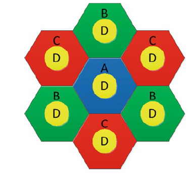 Figure 1: Strict FFR Deployment in LTE Microcell Deployment [4]
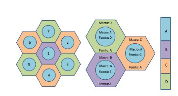 Figure 2: Strict FFR Deployment in LTE Microcell-Femtocell Deployment [25]
From user’s perspective, Integer Frequency Reuse (IFR) can be regarded as a special case of FFR. In IFR, all resource blocks (RBs) allocated to a cell can be used anywhere in the cell without any specification of user’s location. For comparison, the FFR scheme that is selected by adaptive mechanism is compared with variations of IFR. The macrocell coverage area is partitioned into center-zone and edge-zone. The entire frequency band is divided into two parts, one part is solely assigned to the center-zone (e.g., sub-band A in Figure 1) and the other part is partitioned into three subbands (e.g., sub-bands B, C, and D) and assigned to the three edge-zones [26]. Figure 2 shows the Strict FFR network layout for integrated macrocell-femtocell deployment. Note that femtocell uses different frequency bands than the overlay macrocell to minimize or eliminate the inter-tier interference in the network.
3. System Model
A set of multicast users are uniformly distributed in the grid of 16 macrocells. In order to find the optimal inner region radius and frequency allocation in the deployment, the mechanism divides each cell into two regions and calculates the total throughput for the following 40 Frequency Allocations (FA), assuming Frequency Reuse 1 and x for inner and the outer regions respectively [26], where x is the frequency reuse factor of 3. Each FA corresponds to paired value of fraction of inner region resource blocks and inner region radius.
- FA1: All 25 resource blocks are allocated in inner region. No resource blocks are allocated to the outer region.
- FA2: 24 resource blocks are allocated in inner region. 1/x resource block allocated to the outer region.
- FA39: 1 resource block allocated in inner region. 24/x resource blocks allocated to the outer region.
- FA40: No resource blocks are allocated in inner region. 25/x resource blocks allocated to the outer region.
For each FA, the mechanism calculates the total throughput, user satisfaction, user fairness, and weighted throughput values based on new metrics. This procedure is repeated for successive inner cell radius (0 to R, where R is the cell radius). The mechanism selects the optimal FFR scheme that maximizes the cell total throughput. This procedure is repeated periodically in order to take into account users’ mobility. Therefore, the per-user throughput, the cell total throughput, User Satisfaction (US), and other metrics are calculated in periodic time intervals (the exact time is beyond the scope of this manuscript) and at each time interval, the FFR scheme that maximizes the above parameters is selected. This periodic process is called adaptation [28]. The system model described above can be used for supported LTE bandwidths ranging from 1.4 MHz to 20 MHz.
The signal-to-interference-plus-noise (SINR) for downlink transmission to macro user x on a subcarrier n can be expressed as,
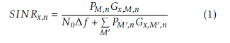 where, PM,n and PM0,n is transmit power of serving macrocell M and neighboring macrocell M0 on subcarrier n, respectively. Gi,M,n is channel gain between macro user i and serving macrocell M on subcarrier n and Gi,M0,n corresponds to channel gain from neighboring macrocell M0. Finally, N0 is white noise power spectral density and ∆f is subcarrier spacing.
The channel gain G, given by the following equation is dominantly affected by path loss, which is assumed to be modeled based on urban path-loss PL is defined as,
![]() Additionally, for the throughput calculation, the capacity of a user i on a specific subcarrier n can be estimated via the SINR from the following equation,
Additionally, for the throughput calculation, the capacity of a user i on a specific subcarrier n can be estimated via the SINR from the following equation,
![]() where, W denotes the available bandwidth for each subcarrier divided by the number of users that share the specific subcarrier and α is a constant for a target bit error rate (BER) defined by α = −1.5/ln(5 · BER). Here, BER is set to 10−6.
where, W denotes the available bandwidth for each subcarrier divided by the number of users that share the specific subcarrier and α is a constant for a target bit error rate (BER) defined by α = −1.5/ln(5 · BER). Here, BER is set to 10−6.
The expression of the total throughput of the serving macrocell M is given as follows,
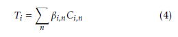 where, βi,n represents the subcarrier assigned to user
- i. When βi,n=1, the subcarrier is assigned to user i. Otherwise, βi,n=0.
4. Mobility Model
This paper evaluates network performance in a scenario with mobile users in the highlighted cell of the topology presented in Figure 3. During the experiment that lasts for 217 seconds, 24 users of the examined cell are moving randomly inside the cell with speed 3 km/h, according to the Pedestrian A channel model [27]. It is assured that all of them remain into the cell’s area, ensuring that their total number will remain constant. This corresponds to low mobility scenario with zero to minimal handover.
5. Performance Metrics
The paper evaluates the network performance for adaptive and non-adaptive FFR mechanisms with user mobility. For comparison, the adaptive FFR scheme that is selected by proposed mechanism is compared with three different cases. The first case, where the optimal inner radius and frequency allocation remain constant through the adaptation process, is referred to FFR nonadaptive. The second case, where the cell bandwidth equals the whole network bandwidth, is called IFR with frequency reuse 1 (IFR1). In the third case, the inner region radius is zero and each cell uses one third of the networks bandwidth. This case is called IFR with frequency reuse 3 (IFR3). The difference with the IFR1 case, lies in the fact that only co-channel base station are considered in interference calculation and as a consequence, the interference base station density is divided by 3.
5.1. Existing Metrics
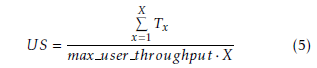
This paper uses a metric US defined by authors in [28]. It is calculated as the sum of the users’ throughput divided by the product of the maximum user’s throughput and the number of users (X). US ranges between 0 and 1. When US approaches 1, all the users in the corresponding cell experience similar throughput. However, when US approaches 0, there are huge differences in throughput values across the users in the cell. This metric will be utilized in scenarios where fairness to the users is significant such as cell throughput and Jain fairness index.
 With metric WT defined by the authors in [28], the aim is to not only generate low variance of the per-user throughput values but also obtain higher values of the cell total throughput.
![]() where T is the cell mean throughput.
where T is the cell mean throughput.
To obtain a metric of fairness for performance evaluation, the Jain fairness metric introduced in [29] is used. Assuming the allocated throughput for user i is xi, Jain fairness index for the cell is defined as,
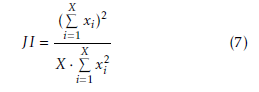 This metric is interesting for the evaluation of the proposed method due to its properties. It is scaleindependent, applicable for different number of users and it is bounded between [0, 1], where 0 means “total unfairness” and 1 means “total fairness” in terms of throughput division among the users.
5.2. Proposed Metric
This section introduces a new metric, weighted throughput based on user satisfaction WTUS, to add weights to the cell throughput corresponding to specific inner radius and inner bandwidth such that the resultant throughput is higher than the corresponding throughput optimized at user satisfaction alone and all the users in the corresponding cell experience similar throughput.
![]() From (6), (8), it is clear that the metrics are cellbased.
From (6), (8), it is clear that the metrics are cellbased.
6. Performance Evaluation
6.1. Mathematical Model
The product model is applied as mathematical model in the new metric definition and development. Previous metric, weighted throughput, adds the benefits of the individual component metrics, throughput and fairness index. Similarly, the proposed metric defined by the product model of throughput and user satisfaction, is expected to perform better than the individual component metrics.
6.2. Simulation Parameters
Table 2 are parameters set for simulation.
Table 2: Simulation Parameters
| Parameter | Value |
| System Bandwidth | 5 MHz |
| Subcarriers | 300 |
| Subcarrier Bandwidth | 180 KHz |
| Cell Radius | 250 m |
| Inter eNodeB distance | 500 m |
| Noise Power Spectral Density | -174 dBm/Hz |
| Subcarrier spacing | 15 KHz |
| Channel Model | Typical Urban |
| Carrier Frequency | 2000 MHz |
| Number of macrocells | 16 |
| Macrocell Transmit Power | 46 dBm |
| Path Loss | Cost 231 Hata Model |
| Users’ speed | 3 km/h PedA |
A sample uniform deployment considered in simulation is shown in Figure 3. Macrocells are located at cell centers. Active users are randomly distributed and are shown with white dots.
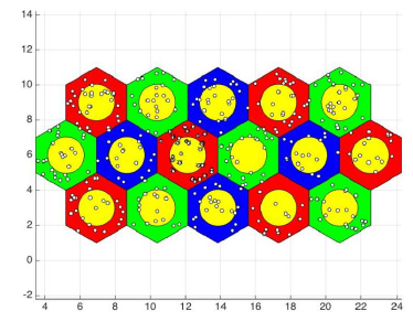 Figure 3: Strict FFR Uniform Deployment for Simulation
6.3. Simulation Guidelines
Note that the simulation is run assuming a stable downlink data traffic, since the simulation framework is analyzing data for downlink traffic. A network snapshot where user association to macrocell remains stable for the duration of the simulation run is considered as the users are associated to the base stations with maximum SINR. A frequent handover will occur in high mobility environment and that is not included in the scope of this paper. The simulation software for our research is based on [30].
6.4. Performance Analysis
6.4.1. Comparison of New Metric to Other Metrics
The new metric is introduced due to the following reasons, better performance in terms of average user throughput and effective user fairness in terms of variance in user throughput. Figure 4 proves the user throughput optimized with new metric shows better performance and low variance.
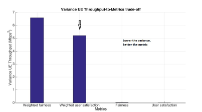 Figure 4: Comparison of Variance in User Throughput
6.4.2. Static Users – Metric Performance
Simulation is carried out by applying the metrics on users with static positions and performance is evaluated with respect to inner region subcarriers and inner region radius. Figures 5 – 8 show the metric performance with respect to inner region subcarriers. Figures 9 – 12 show the metric performance with respect to inner region radius.
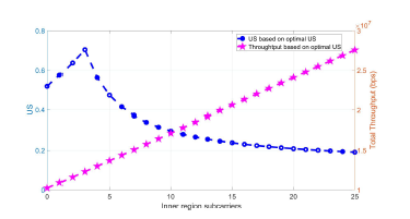 Figure 5: User Satisfaction Metric Performance for Static Users to Inner Region Subcarriers
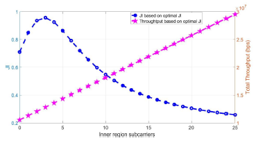 Figure 6: Fairness Index Metric Performance for Static Users to Inner Region Subcarriers
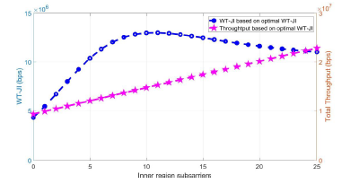 Figure 7: Weighted Fairness Metric Performance for Static Users to Inner Region Subcarriers
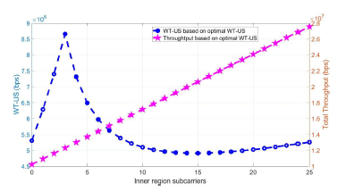 Figure 8: Weighted User Satisfaction Metric Performance for Static Users to Inner Region Subcarriers
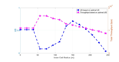 Figure 9: User Satisfaction Metric Performance for Static Users to Inner Region Radius
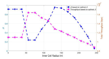 Figure 10: Fairness Index Metric Performance for Static Users to Inner Region Radius
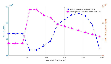 Figure 11: Weighted Fairness Metric Performance for Static Users to Inner Region Radius
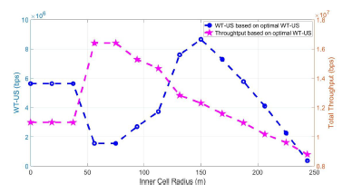 Figure 12: Weighted User Satisfaction Metric Performance for Static Users to Inner Region Radius
6.4.3. Adaptive versus Non-adaptive mechanisms Metric Performance
As user mobility is introduced and new positions are determined, the simulation calculates metrics and optimal inner radius and subcarrier allocation for adaptive and non-adaptive variations for each FFR mechanism. For non-adaptive FFR mechanism, optimal inner radius and subcarrier allocation remain constant even after the user position changes and performance metrics are calculated. For adaptive FFR mechanism, new values of optimal inner radius and subcarrier allocation are determined based on the new user position and optimal FFR performance. Therefore, the adaptive FFR mechanism reacts to user mobility better than non-adaptive FFR mechanism. Figures 13 – 17 show FFR performance for all metrics with adaptive and non-adaptive mechanisms applied. In all the adaptive versus non-adaptive mechanisms comparison results, the adaptive mechanism applied on the metrics perform better than non-adaptive mechanism. Particularly, the proposed metric performance Figure 17 shows higher throughput than other metrics and better performance versus non-adaptive and IFR variations. For both weighted user satisfaction (proposed metric) in Figure 17 and weighted fairness (existing metric) in Figure 16, the adaptation process is visible between 50 to 200 seconds. However, despite common benefit of better reaction to the adaptation process, weighted user satisfaction performs better with higher throughput compared to weighted fairness. There is a co-relation between adaptation trend and inner region radius as shown in Section 6.4.4.
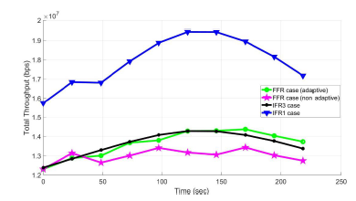 Figure 13: Comparison of adaptive versus nonadaptive mechanisms for Total Throughput
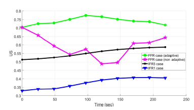 Figure 14: Comparison of adaptive versus nonadaptive mechanisms for User Satisfaction
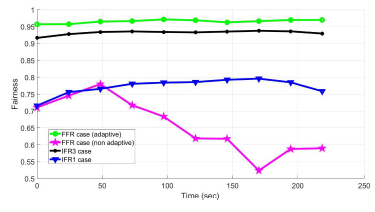 Figure 15: Comparison of adaptive versus nonadaptive mechanisms for Fairness Index
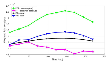 Figure 16: Comparison of adaptive versus nonadaptive mechanisms for Weighted Fairness
 Figure 17: Comparison of adaptive versus nonadaptive mechanisms for Weighted User Satisfaction
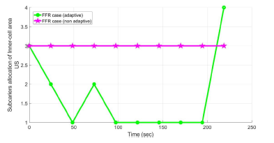 Figure 18: Comparison of Subcarrier Allocation for User Satisfaction
6.4.4. Adaptive versus Non-adaptive mechanisms Subcarrier Allocation and Inner-Cell Radius
The throughput trend optimized for each metric can be explained with inner region subcarrier and inner region radius results. Figures 22 – 25 show effect of adaptation process on subcarrier allocation for all metrics. Figures 22 – 25 show effect of adaptation process on inner region radius for all metrics. Both subcarrier allocation and inner region radius show active response to the adaptation process applied to the network during the simulation time. For weighted user satisfaction, Figure 25 and weighted fairness Figure 24, the subcarrier allocation reacts positively to the adaptation process between 50 and 200 seconds. High throughput trend during this time interval can be explained due to allocation of all 25 subcarriers. Similarly, the range of inner region radius changes with the adaptation process during the simulation time compared to its static trend in non-adaptive mechanism as shown in Figures 25, 24.
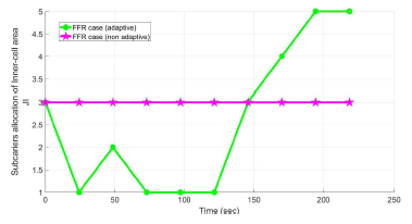 Figure 19: Comparison of Subcarrier Allocation for Fairness Index
 Figure 20: Comparison of Subcarrier Allocation for Weighted Fairness
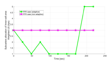 Figure 21: Comparison of Subcarrier Allocation for Weighted User Satisfaction
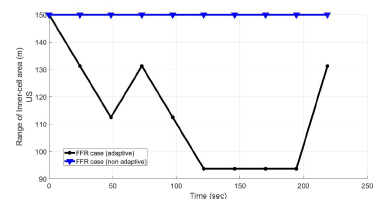 Figure 22: Comparison of Range of Inner-cell for User Satisfaction
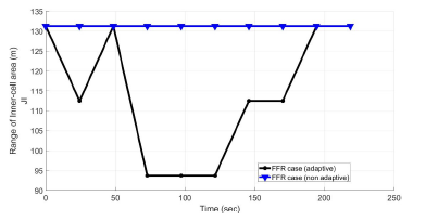 Figure 23: Comparison of Range of Inner-cell for Fairness Index
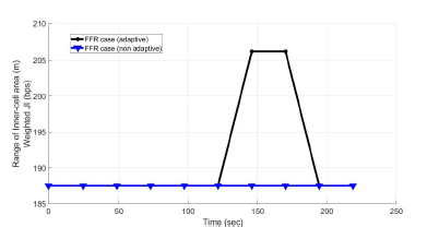 Figure 24: Comparison of Range of Inner-cell for Weighted Fairness
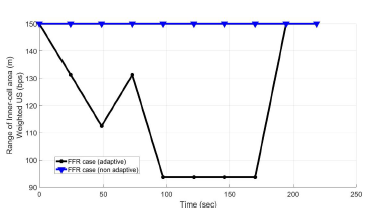 Figure 25: Comparison of Range of Inner-cell for Weighted User Satisfaction
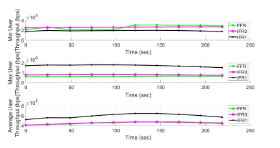 Figure 26: Comparison of Minimum, Maximum, Average for User Satisfaction
6.4.5. Adaptive versus Non-adaptive mechanisms Minimum, Maximum, and Average Values
FFR mechanism simulation compares their minimum, maximum, and average results over time. Figures 26 – 29 show the metric performance. Maximum and average throughput shows lowest performance for FFR mechanism optimized for weighted user satisfaction metric. This is obvious result since the goal of the new metric is to reduce variance in user throughput and maintain relatively high overall throughput.
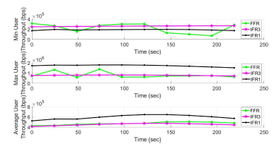 Figure 27: Comparison of Minimum, Maximum, Average for Fairness Index
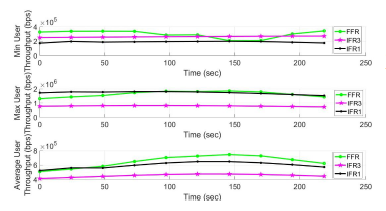 Figure 28: Comparison of Minimum, Maximum, Average for Weighted Fairness
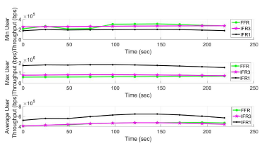 Figure 29: Comparison of Minimum, Maximum, Average for Weighted User Satisfaction
6.4.6. Adaptive versus Non-adaptive mechanisms Femtocells
LTE femtocells have been developed to increase capacity and raise the throughput of cell-edge users. In this simulation, the LTE network is extended with randomly placed femtocells in each macrocell, assuming an uniform femtocell co-channel deployment. Despite the high throughput benefits, femtocell deployment experience relatively high level of interference from neighboring macrocells and femtocells. FFR frequency deployment is set as indicated in Figure 2. Simulation results in Figure 30 and 31 indicate higher throughput due to addition of femtocell radio resources. Adaptive trend is in line with the previous results without femtocells, where the network throughput adapts to the moving user locations. Network throughput optimized to weighted user satisfaction metric shows higher maximum and average throughput compared to IFR1 and IFR3 due to the presence of additional frequency resources.
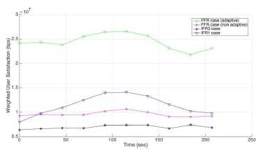 Figure 30: Comparison of adaptive versus nonadaptive mechanisms for Weighted User Satisfaction with Femtocells
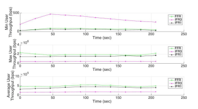 Figure 31: Comparison of Minimum, Maximum, Average for Weighted User Satisfaction with Femtocells
7. Conclusion
In conclusion, the paper evaluated the adaptation process in LTE FFR mechanism. The selected FFR mechanism based on the optimal inner region radius and frequency allocation performed better than other interference co-ordination mechanisms. The FFR mechanism optimized using weighted throughput user satisfaction made a positive trade-off between the existing metrics, as it maintained relatively high total throughput and reduced the variance of per-user throughput. The proposed metric reacted better to the adaptation process in mobility scenarios and generated higher throughput compared to the other metrics. With extreme densification in future mobility, the effect of femtocells on
the network throughput optimized for new metric on moving users was studied. A good research extension would be to review impact of femtocell densification and uniform grid placement on the adaptation process with the proposed metric.
Conflict of Interest
The authors declare no conflict of interest.
- Sawant, R. Akl, “Evaluation of Adaptive and Non Adaptive LTE Fractional Frequency Reuse Mechanisms” in The 26th Annual Wireless and Optical Communications Conference, New Jersey, USA, 2017. https://doi.org/10.1109/WOCC.2017.7928998
- Bilios, C. Bouras, V. Kokkinos, G. Tseliou, A. Papazois, “Selecting the Optimal Fractional Frequency Reuse Scheme in Long Term Evolution Networks” in IEEE Wireless Pers. Communications, 2013. https://doi.org/10.1007/s11277-012-0965- z
- Yadav, M. Palle, A. Hani, “Performance Analysis of Fractional Frequency Reuse Factor for Interference Suppression in Long Term Evolution” in International Journal of Conceptions on Electronics and Communication Engineering, 2015. https://doi.org/10.1109/PGSRET.2015.7312249
- Bouras, D. Bilios, V. Kokkinos, A. Papazois, G. Tseliou, “A performance study of Fractional Frequency Reuse in OFDMA networks” in IEEE Wireless Telecommunications Symposium, 2012. https://doi.org/10.1109/WMNC.2012.6416137
- Bouras, G. Kavourgias, V. Kokkinos, A. Papazois, “Interference management in LTE femtocell systems using an adaptive frequency reuse scheme” in IEEE Wireless and Mobile Networking Conference (WMNC), 2012. https://doi.org/10.1109/PGSRET.2015.7312249
- Bouras, G. Kavourgias, V. Kokkinos, A. Papazois, “Interference management in LTE femtocell systems using an adaptive frequency reuse scheme” in IEEE Wireless Telecommunications Symposium, 2012. https://doi.org/10.1109/WTS.2012.6266120
- Bilios, C. Bouras, V. Kokkinos, A. Papazois, G. Tseliou, “Optimization of fractional frequency reuse in Long Term Evolution networks” in IEEE Wireless Communications and Networking Conference (WCNC), 2012. https://doi.org/10.1109/WCNC.2012.6214087
- Taranetz, J. Ikuno, M. Rupp, “Capacity Density Optimization by Fractional Frequency Partitioning” in IEEE, 2011. https://doi.org/10.1109/ACSSC.2011.6190246
- Ikuno, M. Taranetz, M. Rupp, “A Fairness-based Performance Evaluation of Fractional Frequency Reuse in LTE” in 2013 17th International ITG Workshop on Smart Antennas (WSA), 2013.
- Chang, Z. Tao, J. Zhang, C. Kuo, “A graph approach to dynamic fractional frequency reuse (FFR) in multi-cell OFDMA networks” in In proceedings of IEEE international conference on communications (ICC 2009), 2009. https://doi.org/10.1109/ICC.2009.5198612
- Assad, “Optimal fractional frequency reuse (FFR) in multicellular OFDMA system” in In proceedings of IEEE 68th Vehicular technology conference (VTC 2008Fall), 2008. https://doi.org/10.1109/VETECF.2008.381
- Hassan, M. Assad, “Optimal fractional frequency reuse (FFR) and resource allocation in multiuser OFDMA system” in In Proceedings of International Conference on Information and Communication Technologies, (ICICT 2009), 2009. https://doi.org/10.1109/ICICT.2009.5267207
- Fang, X. Zhang, “Optimal fractional frequency reuse in OFDMA based wireless networks” in Proceedings of 4th international conference on wireless communications, networking and mobile computing, (WiCOM08), 2008. https://doi.org/10.1109/WiCom.2008.166
- Xiang, J. Luo, C. Hartmann, “Inter-cell interference mitigation through flexible resource reuse in OFDMA based communication networks” in Proceedings of European Wireless, 2007.
- Sternad, T. Ottosson, A. Ahlen, A. Svensson, “Attaining both coverage and high spectral efficiency with adaptive OFDM downlinks” in Proceedings of IEEE 58th Vehicular Technology Conference (VTC 2003-Fall), 2003. https://doi.org/10.1109/VETECF.2003.1285981
- Fodor, C. Koutsimanis, A. Rcz, N. Reider, A. Simonsson, W. Mller, “Intercell interference coordination in OFDMAnetworks and in the 3GPP long term evolution system” in Journal of Communications, 2009. https://doi.org/10.4304/jcm.4.7.445-453
- Li, H. Liu, “Downlink radio resource allocation formulti-cell OFDMA system” in IEEE Transactions on Wireless Communications, 2006. https://doi.org/10.1109/TWC.2006.256968
- Godlewski, M. Maqbool, M. Coupechoux, J. Kelif, “Analytical evaluation of various frequency reuse schemes in cellular OFDMA networks” in Proceedings of 3rd international conference on performance evaluation methodologies and tools (Valuetools 2008), 2008. https://doi.org/10.1016/j.peva.2009.08.001
- Lim, R. Badlishah, M. Jusoh, “LTE-fractional frequency reuse (FFR) optimization with femtocell network” in 2nd International Conference on Electronic Design (ICED), 2014. https://doi.org/10.1109/ICED.2014.7015863
- Elfadil, M. Ali, M. Abas, “Fractional frequency reuse in LTE networks” in 2015 2nd World Symposium on Web Applications and Networking (WSWAN), 2015. https://doi.org/10.1109/WSWAN.2015.7210297
- Yen, Q. Zhan, H. Minn, “New Fractional Frequency Reuse Patterns for Multi-Cell Systems in Time-Varying Channels” in International Journal of Conceptions on Electronics and Communication Engineering, 2015. https://doi.org/10.1109/LWC.2015.2404787
- Shahsavari, N. Akar, B. Hossein Khalaj, “Joint Cell Muting and User Scheduling in Multi-Cell Networks with Temporal Fairness” in CoRR, 2016.
- Chang, I. Rubin, “Optimal Downlink and Uplink Fractional Frequency Reuse in Cellular Wireless Networks” in IEEE Transactions on Vehicular Technology, 2015. https://doi.org/10.1109/TVT.2015.2425356
- Mahmoud, O. Elgzzar, S. Hashima, “An accurate model of worst case signal to interference ratio for frequency reuse cellular systems” in 2016 11th International Conference on Computer Engineering and Systems (ICCES), 2016. https://doi.org/10.1109/ICCES.2016.7822037
- Saquib, E. Hossain, D. I. Kim, “Fractional frequency reuse for interference management in LTE-Advanced HetNets”, in IEEE Wireless Communications, 2013. https://doi.org/10.1109/MWC.2013.6507402
- Lee, T. Lee, J. Jeong, J. Shin, “Interference Management in LTE Femtocell Systems Using Fractional Frequency Reuse” in The 12th International Conference on Advanced Communication Technology (ICACT), 2010. https://doi.org/10.1109/PGSRET.2015.7312249
- Technical Specification Group RAN, “Technical Specification Group RAN, E-UTRA; LTE RF system scenarios” in 3GPP Tech. Rep. TS 36.942, 2008. https://doi.org/10.1109/PGSRET.2015.7312249
- Bouras, V. Kokkinos, A. Papazois, G. Tseliou, “Fractional Frequency Reuse in Integrated Femtocell/Macrocell Environments” in IEEE WWIC, 2013. https://doi.org/10.1007/978-3- 642-38401-1 18
- Jain, D. Chiu, W. Hawe, “A Quantitative Measure of Fairness And Discrimination for Resource Allocation in Shared Computer System” in DEC Technical Report 301, 1984. https://doi.org/10.1109/PGSRET.2015.7312249
- Research Unit 6, “FFR Scheme Selection Mechanism”, 2013. http://ru6.cti.gr/ru6/FFR selection mechanism.zip