The method of correlation investigation of acoustic signals with priority placement of microphones

Adv. Sci. Technol. Eng. Syst. J. 3(1), 412–417 (2018);
 DOI: 10.25046/aj030150
Examples of analytical calculations of the system characteristics of the hardware and time complexity of the correlation system based on a certain number of microphones and the corresponding number of interrelations are presented. The structural solutions of the hardware special processor implementation of such class of multichannel devices for recognition and identification of types and the spatial location of sources of acoustic signals are developed. The structural model of the spatial identification of sources of acoustic signals in Cartesian coordinates of a two-dimensional Hamming space with the priority placement of microphones as receivers of acoustic signals is proposed.
1. Introduction
This paper is an extension of work originally reported in 14th International Conference the Experience of Designing and Application of CAD Systems in Microelectronics (CADSM) [1].
Development of theoretical foundations of information technology and software – hardware correlation signal processing is actual scientific – applied problem is to be solved in many industries. Identification of sources of acoustic signals (SAS) relative spatial placement of microphones – receivers of acoustic signals (RAS) is also included. The given problem is a primary-industry-technical task of the special technique [2–4].
Analysis of the known research results. In [5–8] the authors created successful but far from optimal solution of such problem is working out localization accumulated information systems. The determination of spatial parameters (θ) azimuth and distance to the SAS (φ) the use of a certain number of (q) correlates for a given number of those (m) microphones is taken as the base of the system.
The example of the structure of Acoustic Localization by Accumulated Correlation (ALAC) system [5] is shown in Figure 1.
It should be noted that the number of required correlators for a given number of chaotic space placed microphones RAS is determined by the condition of symmetry correlation matrix (1).
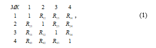 where , are placed along the diagonal; are identical, according to the symmetry of the matrix (1).
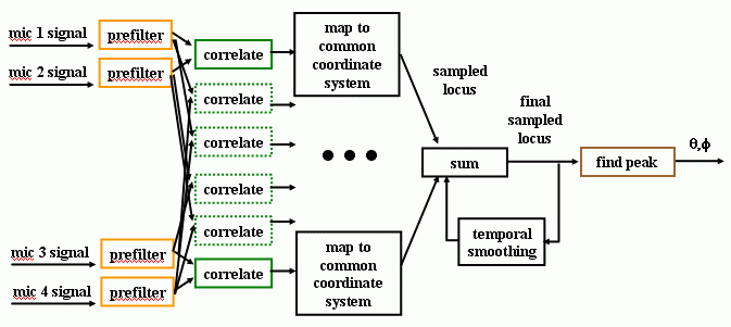 Figure 1. Structure of the ALAC
So, according to the information technology of the correlation processing of the SAS signals in ALAC system, the required amount of (q) correlates for a given number of the (m) microphones is determined by the expression:
![]() The graph of dependency (2) with different numbers of microphones is shown in Figure 2.
The graph of dependency (2) with different numbers of microphones is shown in Figure 2.
For implementation of each correlator in ALAC system the integrated assessment multiplicative correlation function is used by the expression:
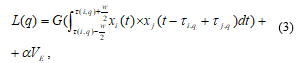 where: – the identifier of the SAS; – the integrated cross-correlation function; and – current and delayed on the time interval acoustic signals (AS) accordingly; damping energy coefficient of the cross-correlation function on the interval .
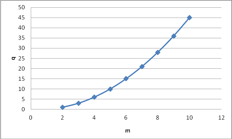 Figure 2. The dependence of the required number of correlators on the number of microphones in the system
The analysis of the analytic expression (3) allows to determine that the implementation of correlates in ALAC system is based on a time delay, multiplying and integrating analog signals, essentially limiting its functionality, simplifying and increasing the speed and accuracy also prevents it implementation based on digital microelectronics crystals and programmable integrated-circuit logic (FPGA).
The purpose of the work is to develop and explore systemic and structural characteristics of digital special processor computing centered multiplicative correlation function.
2. Formulation of the problem
The purpose of the work is to develop a digital correlator to determine the location of the acoustic signal source.
In order to study the principles of improving and optimizing system features of digital correlators as the basic components of the discovering system, analysis of system features of special processor and computing digital multiplicative correlation estimates by the expression is carried out [9]:
 where: – is centered autocorrelation function; and – are centered digital value and analog signals and ;– is the volume of the sample data set ; – is the number of points of correlation function ;– is discrete digital delay unit point in time.
The example of the interaction in time of the digital signals and, where C – constant threshold and corresponding asymptotic of the correlation function is shown in Figure 3.
 Figure 3. Example of temporal interaction sampled in time and amplitude quantized digital signals and corresponding digital asymptotic estimates multiplicative correlation function in conventional units (c.u.)
Figure 3 shows that at the time of coincidence the current digital streams until the moment of the reception of acoustic signal by a remote microphone SAS level of correlation between the previously obtained a SAS close to the microphone signal to digital value – s correlator outputs do not exceed the threshold level constant and at the time of singing falling at the time fixed main lobe function and accordingly a numeric value that corresponds to the duration used for direction finding SAS. Obviously, depending on the structure of the stream of digital samples that reflect the analog signal generated by a remote SAS in the vicinity of the main lobe functions will emerge sufficiently large lateral lobes, which require separate examination for specific researched objects that have SAS.
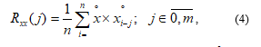
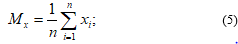
In [10] the authors showed that in general for calculation the correlation function according to expression (4) based on a processing arrays of digital data which representing the converted analog-to-digital converter (ADC) input analog signals you should do the following:
- define the digital evaluation expectation:
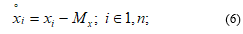
 calculate the array centered values:
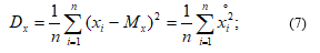
 calculate the variance:
 calculate the correlation function centered on the expression (4);
- calculate the normalized correlation function:
 perform the comparison of the digital value which changes in boundaries , with boundary constant :
 register a digital value which corresponds to the time delay of the acoustic signal between two microphones placed at different distance from SAS.
This correlation algorithm of digital processing acoustic signals on a base of multiplicative function (4) is greatly simplified if before the analog-to-digital converter (ADC) pre-differentiation analog signal is performed and it is passed through a device of automatic gain control.
Such pre-processing of the analog signals and , which are formed on the outputs of the microphones allows to remove from algorithm of calculating operations (5–8) and immediately calculate correlation digital integrated assessment (4) and compare it values at all points of the constant threshold
As it will be shown later, the numerical value of this constant is selected due to the given parameters of digital correlator, which implements the calculation of the multiplicative function. Such parameters are:
- the number of quantization levels of analog signals
- binary output bit ADC
- the sample size of the database
- the number of points correlation function
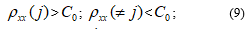
The basic structure of the investigated correlation processing of acoustic signals special processor designed for their processing is shown in Figure 4.
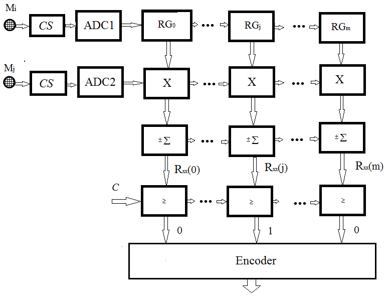 Figure 4. The basic structure of the digital special processor for correlation processing of acoustic signals
The following notions are used in Figure 4: – RAS microphones; CS – conditioners signals; ADC – analog-to-digital converter; – multi bit shift register source ; Х – digital binary multiplier; – reversing saving up adder; – module comparing numerical values of the correlation function threshold constant C; encoder – encoder codes Haar – Rademacher.
The work of the digital correlator is as follows. Acoustic signals which are taken by microphone and with a certain time lag are converted to electrical signals which passing through conditioners signals (CS) are filtered, normalized on power and enter the inputs of the first ADC1 and second (ADC2) alternating analog – digital converters parallel type.
Output k – bit binaries ADC1 come to k – bit input of the multibit shift register (MSR) where are stored in memory registers, the outputs are fed to the first digital multipliers inputs (X). Binary k – bit codes that are generated at the output ADC2 with a certain time delay corresponding to the time delay of acoustic signals , which are simultaneously fed to all second input () k – bit binary multipliers (X), the outputs of which received 2k – bit binaries enter the relevant inputs – bit reversible accumulating adder (), where codes are received digital values point correlation function .
Simplification of operations of division by sample size data set (n) in formula (4) is achieved throughout its multiplicity of 2 degrees, allowing to get the average value of digital codes point correlation function by discarding four junior level in the original binary code accumulating Obtained codes with the bit 2k, or with less precision 2k–r, where r = 2,4,6, … are compared to the corresponding () module compare (), the output of which is formed m – bit position code Haar type (00 … 10 … 0) , the position “1” of which corresponds to the numerical values of the time delay of acoustic signals received by spatially located microphones and .
For example, when the number of points of the correlation function m = 4096 binary code has 12 bits, that corresponds to = 0.0025 measurement accuracy and uncertainty, and at m = 1024, corresponds to 10-bit binary code and the accuracy does not exceed = 0.001.
The structural scheme shown in Figure 4 can be used for measuring the distance to the SAS by gradient method in case when the source and signal receivers are located anyone line. The example of gradient method is demonstrated in Figure 5.
 Figure 5. Spatial diagram of SAS capacity changes
The distance to the source is defined by formula
where:– is the coefficient of acoustic sound energy attenuation in the atmosphere; – capacity difference of the signals received from the first and second microphones.
3. Structure of the proposed correlator
The analysis of the expression (4) and the structure of the corresponding digital special processor shows that the presence of the centering operation and the multiplication of alternating digital codes complicates the implementation of such a special processor and significantly reduces its performance compared to its functionally equivalent implementation based on the Hamming distance estimation according to the expression
![]() where centering and multiplication operations are not applied. The application of the Hamming distance estimation based on the calculation of the modular correlation function allows to realize the operation of determining the modular difference between the two digital values in the microelectronic performance proposed in [9] according.
where centering and multiplication operations are not applied. The application of the Hamming distance estimation based on the calculation of the modular correlation function allows to realize the operation of determining the modular difference between the two digital values in the microelectronic performance proposed in [9] according.
The purpose of improving the ALAC correlation system is:
- implementation of the digital representation and correlation acoustic signals processing;
- reduction of the number of digital correlations of the system;
- reduction of algorithmic and hardware complexity and increase of speed of digital correlators;
- implementation of the tabular method for the identification of the spatial location of sources of acoustic signals based on time delay of acoustic signals between microphones;
- adaptation of the digital correlator to the form of an acoustic signal generated by different sources of sound.
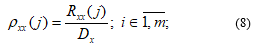
To meet these objective, a method of correlation processing of the acoustic signal with priority placement of microphones [11,12] is proposed on the basis of the multiplicative function (4) converted to the normalized form (8).
Despite successful problem solution for determining time delay of acoustic signals between microphones, such structure of a special processor does not allow to determine independently the spatial coordinates of the source of acoustic signal since it requires more than one base. That is, the number of hardware equipment of such a system increases almost twice. In addition, the use of multiplicative correlation functions and requires the implementation of modules for the multiplication and accumulation of reversible interchangeable digital data which considerably complicates the algorithm for processing digital data and the hardware implementation of such a system.
In order to optimize the characteristics of the investigated correlation system the authors propose to implement it on the basis of three microphones, with the priority of spatial placement of one of the microphones at the testbed, and the application of a modular correlation function which allows to identify time delays between acoustic signals , and based on the estimation of the Euclidean distance in the Hamming space.
Implementation of the principle of digital processing of acoustic signals allows to reduce significantly the hardware complexity of a single two-channel correlator. The structure of the system is shown on Figure 6.
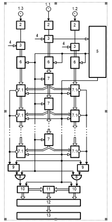 Figure 6. Flowchart of multichannel device for the calculation of modular correlation function
Multi-channel device for calculation of modular correlation function consists of: 1.1, 1.2, 1.3 – respectively: the first priority, second and third receivers of acoustic signals; 2 – amplification automatic adjustment; 3. matched filter of acoustic signals; 4 – reference acoustic signal input; 5 – synchronizer; 6 – parallel-type ADC with output source codes in the binary numeral system of the Rademacher theoretic-numerical basis; 7 – multichannel shift register; ; 7.1 – reverse-accumulation adder; 8 – logical elements AND; 9 – threshold storage of modular differences; 10- RS – triggers; 11 – binary counters; 12 – modular-difference adder; 13 coordinate system based on read-only memory (ROM).
At the beginning of the operating cycle of the device signal So of the first output synchronizer 5 generates initial pulse, which resets the memory registers of all cumulative adders of modular differences 9, trigger inputs 10, and binary counters 11 to the zero state.
Input analogue acoustic signals x (t), y (t), z (t), which are generated by a remote source of acoustic signals, enter the input of the acoustic signal receiver 1.1 which is spatially closer to the source of acoustic signals and with some delay in time and . Correspondingly, they enter the inputs of related acoustic signal receivers 1.2 and 1.3. Being formed on the outputs of the acoustic signal receivers 1.1, 1.2 and 1.3, electrical signals come to the inputs of the corresponding devices of automatic amplification adjustment 2. Electric signals are produced at their output terminals and are normalized by amplitude and positive indicative potential. Generated, output signals of the automatic amplification adjustment devices 2 flow to the first inputs of matching filters 3. The second filter inputs are connected to the input terminals of reference acoustic signal input 4, and the outputs are connected with the first inputs of corresponding ADC 6.
During the operation cycle of the device the clock signals of the second output of the synchronizer 5 Sx synchronize the formation of source codes xi,yi and zi on the outputs of the corresponding ADCs 6, the corresponding shifts of the digital codes xi-j in the multichannel shift register 7, and pulses coming from the outputs of the corresponding logic elements AND 8 on the inputs of the corresponding counters 10. At the same time, corresponding threshold amounts s are formed in the accumulated aggregates of the modular differences 9 of the first and second groups, the excess of which causes the formation of a zero potential which converts the corresponding trigger 10 into a single state of the S-input in one of the channels of each group on the inverted outputs of adder accumulator of modular differences 9.
The accumulated amount of impulses in the first counter 11 and in the second counter 11 enters the first and second inputs of the coordinate system 12, and the resulting modular difference in the modular increment adder 12, enters the third input of the coordinate system 13, the output in the form of a code . This is the output of the device. Figure 7 shows a timeline diagram of the formation and processing of acoustic signals with the registration of time delays between three microphones, and and corresponding values of the source sound coordinates selected from ROM.
For example, at 1 м; , , which corresponds to the binary codes i and j with 8 bit capacity, the number of sound identified sources with coordinates equals 1282=8192, and with and respectively , and with and equals respectively . Hence, it corresponds to the spatial dimensions of the testbed targets and m.
4. Research results
The application of multiple autonomous systems of parallel direction finding of acoustic signal sources with respectively small number of nodes in the Hamming space allows to reduce significantly the accuracy requirements of the digital representation of values , and .
The required memory for tactical representation of coordinates of the acoustic signal source at and equals 256 Kbytes.
Generalized chart of acoustic signal processor operation in the Hamming distance based on the modular correlation function is shown on Figure 8.
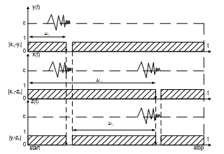 Figure 7. Timeline diagram of code correlation-modular formation of acoustic signal time delay.
 Figure 8. Basic structure of digital special processor for correlation processing of acoustic signals in the Hamming distance
The accuracy of the proposed digital correlator depends on:
- the resolution of a multichannel shift register (Figure 6, element 7);
- the size of square of a Hamming space (Figure 8), which is stored in
5. Conclusions
The purpose of the work was to develop a structure of a digital correlator to determine the location of the acoustic signal source.
Concept design of an automatic system to determine the location of the acoustic signal source has been proposed. It is based on open architecture and provides connection of multiple autonomous acoustic receivers to the system of correlation special processor using wireless communication channels. This allows automatic collection, processing and data transfer regarding operational conditions in the coverage area of acoustic receivers.
The proposed method of optimizing the structure of multi-channel digital correlates with priority spatial placement of a microphone and application module correlation function to process acoustic signals can significantly simplify the algorithm of calculations, reduce the hardware complexity correlates. This allows enhancing its performance, justifying feasibility and effectiveness of these solutions in the established system of monitoring sources of acoustic signals. The proposed chart allows reducing the number of correlators by 3 times.
Conflict of Interest
No conflict of interest in this paper has been identified.
- Bohdan Trembach, Roman Kochan, Rostyslav Trembach, “The method of correlation investigation of acoustic signals with priority placement of microphones”, in 14th IEEE International Conference on The Experience of Designing and Application of CAD Systems in Microelectronics (CADSM), Polyana, Ukraine, 2017.
- M. Krivosheev, V.N. Petrenko, A.I. Prikhodko, Fundamentals of artillery reconnaissance, Sumy State University, 2014.
- R. Kochan, B. Trembach, “The concept of distributed automated system of sound artillery intelligence-based provider” Modern information technologies in the sphere of security and defence, 1, 59–63, 2016.
- E. Trofymenko, Y.G. Filipenko, Sound intelligence station – 100 years, Sumy State University, 3, 198–202, 2009.
- T. Birchfield and D. K. Gillmor. Acoustic Localization by Accumulated Correlation. [Online]: http://www.ces.clemson.edu/~stb/research/acousticloc/
- T. Birchfield. A Unifying, “Framework for Acoustic Localization” in 12th European Signal Processing Conference (EUSIPCO). Vienna, Austria, 2004.
- T. Birchfield and D. K. Gillmor, “Fast Bayesian Acoustic Localization”, in the IEEE International Conference on Acoustics, Speech, and Signal Processing (ICASSP), Orlando, Florida, 2002.
- T. Birchfield and D. K. Gillmor, “Acoustic Source Direction by Hemisphere Sampling”, in the IEEE International Conference on Acoustics, Speech, and Signal Processing (ICASSP), Salt Lake City, USA, 2001.
- Albanskiy, V. Pikh, T. Zavedyuk, G. Korniychuk, “Theory and Special Processors of Spectral Cosine Fourier Transformation Based on Various Correlation Functions in Hamming Space” in 11th International Conference on Modern Problems of Radio Engineering, Telecommunications and Computer Science (TCSET), Slavske, Ukraine, 2014.
- Trembach R.B., Trembach B.R., Sydor A.V., Device of adding multi-bit binary numbers, Ukrainian patent No.117789, 2017.
- Bohdan Trembach, Roman Kochan, Rostyslav Trembach, “Multiplex digital correlator with high priority deployment of one of the acoustic signal receivers”, Scientific Journal of TNTU, 4(84), 99-104, 2016.
- Bohdan Trembach, Roman Kochan, Rostyslav Trembach “Methods of structural design optimization of software hardware problem identification of the spatial parameters of acoustic signals sources”, Scientific Journal of KNU, 1(245), 136-139, 2017.
No related articles were found.