Simulation and FPGA Implementation of a Ring Oscillator Sensor for Complex System Design
 , Idir Mellal 1, Ouafaa Ettahri 1, Mohamed Tabaa 2, Ahmed Lakhssassi 1
Adv. Sci. Technol. Eng. Syst. J. 3(1), 317–321 (2018);
 DOI: 10.25046/aj030138
This paper, presents the design of a temperature sensor based on RO (Ring Oscillator) in order to make a thermal study for the detection and localization of thermal peaks in a complex system. In this work, a simulation and FPGA implementation of a fully digital temperature sensor features a number of exact inverters that can be dynamically inserted. Before the transition to the implementation in FPGA board, the use of VHDL code is necessary to describe the exact number of inverters that form a single ring oscillator, in order to verify and validate the results obtained. This paper offers a solution to thermally induced stress and local overheating in complex system design which has been a major concern for the designers during the design of integrated circuit. In this paper a DE1 FPGA board cyclone V family 5CSEMA5F31C6 is used for the implementation.
1. Introduction
Decreasing feature sizes and increasing power and package contact densities are making thermal issues extremely important in complex system design. The main purpose of using a temperature sensor is to provide thermal monitoring for predicting local overheating or thermally induced stress. In this article, an intelligent sensor is used for thermal monitoring which is almost an ideal sensor due to its low power consumption. The main idea of this work is to simulate and implement a fully digital temperature sensor that can be dynamically inserted, operated and eliminated from the circuit once the test is done.
The intelligent sensor used in the design is actually based on ring oscillator. One of the important questions in the field of thermal issues of VLSI systems and micro-systems is how to perform the thermal monitoring, in order to indicate the overheating situations, without complicated control circuits.
Traditional approach consists of placement of many sensors everywhere on the chip, and then their output can be read simultaneously and compared with the reference voltage recognized as the overheating level. These techniques, though helpful to reduce the overall power consumption, may cause significant on-chip thermal gradients and local hot spots due to different clock/power gating activities and varying voltage scaling. It has been reported in [1] that temperature variations of 30 °C can occur in a high-performance microprocessor design.
The magnitude of thermal gradients and associated thermo-mechanical stress is expected to increase further as VLSI complex designs move into nanometer processes and multi-GHz frequencies. After the actual temperature is read, the value will be returned through the configuration ports of the FPGA. Then, the sensor will be removed from the chip. This type of oscillator used here is based on the switching time of an inverter. By connecting an odd number of inverters, a naturally oscillating signal is obtained at the output of each inverter of the chain. The oscillation frequency is directly related to the number of inverters. The more inverters there are, the lower the frequency is. To control the oscillation, an inverter can be replaced by a NAND gate, in order to stop or activate the oscillating system. Reference [2], [3], [4], [5] and [6] presents various techniques for varying the frequency of oscillation of the structure. These suggestions based on the voltage control of the delay generated by each cell, on the current control of the rise and falling time of each cell or on the controlled variation of the number of cells.
The advantage of this structure lies in the fact that it can be implemented both with an even number and an odd number of cells. This offers a greater tolerance on the constellation in phase of the signals available at output, but in the case of an implementation with an odd number of cells gives a sinusoidal signal in the output which makes the ring oscillator the perfect solution used ever to give more information during the thermal monitoring. In fact, a ring oscillator consists of a feedback loop that includes a necessary odd number of inverters to produce the displacement of the phase which maintains the oscillation the total period is twice the sum of the delays of all the elements that make up the loop. Reversals can be made using the LUT (look-up table) of the configurable logic blocks (CLBs) or the programmable inverters included in the FPGA blocks. In any case, it is useful to insert an external signal to open the loop, as well as an output register to prevent variations in the frequency due to different loads. Thus, the sensor can give instantaneous temperatures.
The future of detectors based on the ring oscillator method is to help designers of more complex integrated circuits to optimize the management of thermal dynamics on the chip [7], [8] and [9]. In this paper in particular, the sensor used allows the detection of thermal peaks. The interests of a sensor based on this method are multiple [10] and [11]. Among the interests of the use of this sensor based on ring oscillator method, is that it can be easily integrated on a chip and can be dynamically inserted or removed from the design at any time due to its small size.
The rest of our work is organized as follows. Section 2, gives a description of the methodology used. Section 3, shows the implementation of the ring oscillator on the FPGA board to verify and validate the results.
2. Description of the methodology used
The new methodology adopted is to validate the control temperature of complex microsystems on a chip based of five inverters forming a ring oscillator [12]. This methodology has given very encouraging results for thermal monitoring in more complex integrated circuits. These simulations and FPGA implementation will then be generalized in high density microsystems, for the development of an integrated thermo mechanical stress control unit using our proposal described in this paper. The proposed ring oscillator depends on the temperature and its frequency changes accordingly. At a given temperature, the oscillator will exhibit a fixed frequency of oscillation.
2.1. Material and geometry of the complex design in COMSOL
We have made the simulation in COMSOL tool appointment with different materials and hardware layers and well on their ranking on the semiconductor. In this figure, we clearly see the reconciliation of our complex circuit layers. The complex model contains 36 Radial Board (RB) in which each RB contains 12 adapter board detector module (ABDM) and each ABDM contains 2 ASICs. Power of 0.6 W is dissipated in a complex circuit of the ASIC (4.68 mm x 5.97 mm) [13]. This amount of power is applied for 9 seconds to visualize the evolution and distribution of heat around the ASIC. Figure 1 shows the ASIC and its support modeled in COMSOL, the ASIC transmits event data through low voltage differential signaling links. To solve the thermal diffusion equations, the Dirichlet boundary conditions (DBC) at 298.15 °K are applied around the daughter board.
 Figure 1 The ASIC modeled by the COMSOL tool.
This structure thus represents a continuous domain, by the method of finite elements consists first of a geometric discretization. The structure is subdivided into sub domains of the simple geometric form called finite element and defined not on the whole of the structure, but for each of its elements.
2.2. Thermal distribution of the complex design in COMSOL
It is very interesting to have a simulation environment that includes the ability to add different physical phenomena to the model studied. In this part, we will present the simulation results from heat sources represented the ASIC complex module in COMSOL tool. As you can see in Figure 2 shows the thermal behavior of our model complex design.
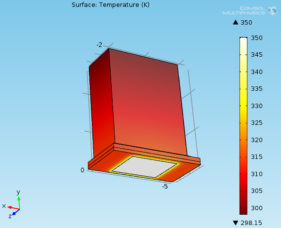 Figure 2 Thermal distribution of the ASIC in COMSOL tool.
This simulation of the ASIC complex module in COMSOL gives a good idea of the behavior and the thermal diffusion of heat sources in our complex system and shows the temperature up to 350 °K. The use of COMSOL tool gives us an idea about the thermal diffusion around the ASIC. According to another study done by [14] and the following Figure 3 presents the values of the temperature as a function of the frequencies of a ring oscillator.
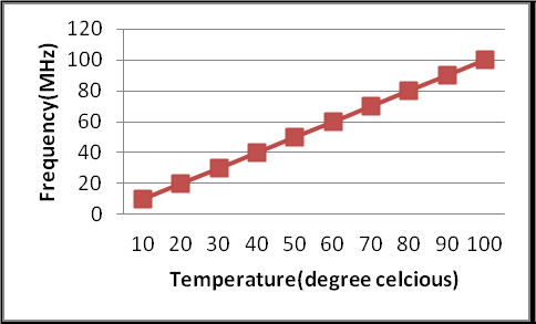 Figure 3 Température of (RO) ring oscillator showing frequency of oscillation linear to temperature.
this research which is done by [14] and the presentation of the results in ghraph form of integrated thermal sensors to monitor the temperature between 10 C to 100 C, according to our simulation under the tool COMSOL Fig. 3 and the study which is done by [12], we can deduce that temperature 77 ° C has our complex module corresponds to approximately 78 MHz (see Fig. 3). This perfectly corresponds to our simulation which is made for the ring oscillator with 5 inverters.
Now we need to validate these theoretical findings find by implementing a 5-inverter based sensor on an FPGA board that allows for different simulations, in [2] explains that more information can be found on the location of the thermal peak at the same frequency and the same temperature of the ring oscillators knowing that this type of ring oscillator sensor can only determine the necessary information if it receives sinusoidal signals, therefore a sinusoidal signal as an input.
3. Experimental implementation and results
The main purpose of this section is the implementation and validation of a single ring oscillator composed of five inverters. VHDL code is used to describe the RO module to facilitate the development of its architecture for its implementation in complex system design. This architecture is modeled in high-level language and simulated to assess its performance and finally implemented on FPGA. The simulation results are validated by using the software Modelsim under Quartus Prime, which allows simulating the behavior of the system in time. Our design flow will be divided into three main parts: simulation, synthesis, and implementation of the VHDL code on FPGA. A description of each part will be presented in the next paragraphs.
3.1. Creation and simulation of the VHDL code
This part, presents the description of the single ring oscillator based of five inverters using a VHDL code editor. The code editor used is Modelsim. Figure 4 shows the top-level module of a single ring oscillator.
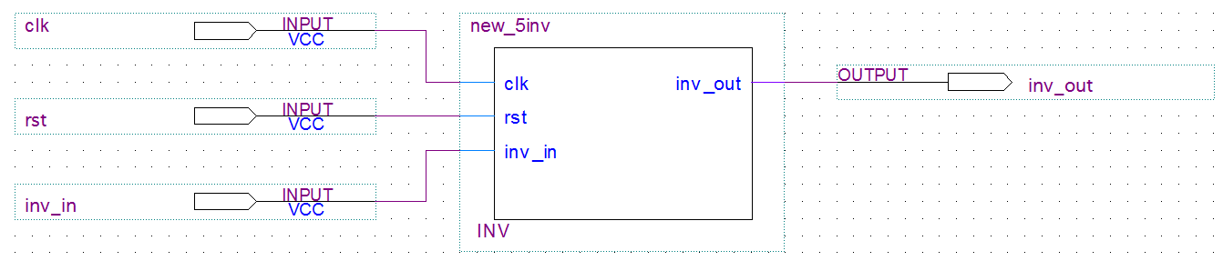 Figure 4 Top level of the ring oscillator composed of five inverters.
This structure in Figure 4 shows the top level of the ring oscillator composed of five inverters, this facilitates the simulation of the logic circuits thereafter. After having followed it, the modelization of a logic scheme of a ring oscillator based on five inverters with Quartus Prime and comes as the next step then the simulation step using ModelSim.
After generating the two .vhd files (the primary file system and the “Test Bench” file) with the “System Generator” the role of the Quartus Prime Navigator comes in order to synthesize the design and generate the RTL files as shown in Figure 5.
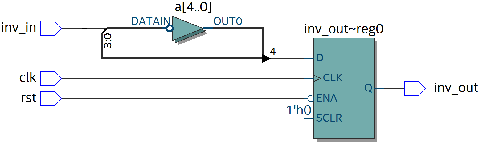 Figure 5 Structure of ring oscillator based five inverters in Quartus Prime tool.
The structure of the single ring oscillator based of five inverters, after synthesis with Quartus Prime from Altera is shown in (Figure 5). The VHDL code implemented was validated. In this part the simulation will be run with the same conditions used in [11], [12] and [14], to validate the experimental results. This Figure 6 shows the results found by the simulation using the Modelsim tool.
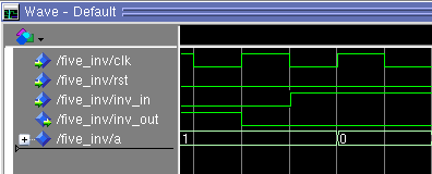 Figure 6 Display résulte of simulation the VHDL code.
As you can see in Figure 6, the signals of simulations are explaining the role of inverters for example for the logical value zero the output is the logical value 1 and the same thing for the second case. The results found validate the VHDL code since it is the correct operation of a single ring oscillator based on five inverters. In this paper, the GDS (gradient Direction Sensor) method for thermal peak detection is used, simulated and verified with a VHDL code and a ‘test bench’ at the laboratory LIMA the results found meet the initial specifications.
3.2. Implementation and downloading of the VHDL code
Once compiled after the assignment of the pins, the program is ready to be downloaded on the card DE1 cyclone V family and 5CSEMA5F31C6 as a device. This Figure 7 shows that the VHDL code is downloaded successfully on the card.
 Figure 7 Downloading the code of DE1 Altera cyclone V.
After the download, the program was running and then the outputs were shown on the display of the card. The clock is at 50 MHz, so the outputs should change with a frequency of 50 MHz and the following Figure 8 shows the two values (1 and 0) after implementation on the LCD.
 Figure 8 Validation of simulation results on the LCD after the implementation of DE1 Altera cyclone V.
This validation of the simulation results in Figure 8 shows that the value displayed on the LCD matches the results found before. The simulation and implementation on FPGA board DE1 can be applied in any kind of environment to get improved performance to control temperature of complex system design on a chip based of five inverters that will form a single ring oscillator with respect to the conventional schematic; it is also able to keep the temperature constant at the desired value regardless of changes in the load or environment. Thus, the overshooting problem can be solved up to great extent. One of the important issues in the field of electronics is overheating problems especially when it comes to integrated and complex systems and microsystems, but the mean question is how to perform thermal monitoring, to indicate overheating situations, without control.
This type of sensors all over the chip, and then their output can be shown simultaneously and be compared to the reference voltage recognized as the level of overheating. The idea of the proposed method is to validate the results predict the local temperature and gradient along the given distance in some places only on the monitored surface and evaluates obtained several real-time information in a short area in order to predict the temperature of the heat source. These peaks found are essential when monitoring the thermal matrix to avoid a critical induced thermo-mechanical stress. In addition, in most cases, overheating occurs in only one location.
4. Conclusion
The main objective of this paper is to simulate and implement a temperature sensor based on ring oscillator to make a thermal study at the junction. For this paper, we presented an experimental study for the implementation of a fully digital temperature to be dynamically inserted, operated and removed from the circuit after the test. Thus, the main advantage of this type of sensor is the analysis of the temperature during operation of the different blocks of a complex circuit implemented on FPGA. This will be useful for the integrated circuit designer because it offers a solution to thermally induced stress and local overheating in complex system design which has been a major concern for the designers during the design of integrated circuits.
- Gronowski et al., “High performance microprocessor design,” IEEE J. Solid-State Circuits, vol. 33, pp. 676– 686, 1998.
- Oukaira, A, Ettahri, O and Lakhssassi, A “Modeling and FPGA implementation of a thermal peak detection unit for complex system design”, (IJACSA) International Journal of Advanced Computer Science and Applications, vol.8, no.6, pp.307-312, 2017.
- Slattery, D. O’ Mahoney, E. Sheehan, and F. Waldron, “Sources of Variation in Piezoresistive Stress Sensor Measurements,” IEEE transactions on components and packaging technologies, vol.27, no.1, pp.81-86, 2004.
- Banu, “100 khz – 1 ghz Nmos Variable-frequency Oscillator With Analog and Digital control,” ISSCC, Solid-State Circuits Conference. Digest of Technical Papers, vol.31, pp.20-21, 1998.
- Retdian, , S. Takagi, and N. Fujii, “Voltage controlled ring oscillator with wide tuning range and fast voltage swing,” IEEE Asia-Pacific Conference, ASIC Proceedings, pp.201-204, 2002.
- Oukaira, A, Pal, N, Ettahri, O, Kengne, E and Lakhssassi, A “Simulation and FPGA Implementation of Thermal Convection Equation for Complex System Design”, (IREA) International Journal on Engineering Applications, vol.2, no.6, pp.307-312, 2016.
- Pinel, Stephane, et al, “Thermal modeling and management in ultrathin chip stack technology”, IEEE Transactions on Components and Packaging Technologies, vol.25, no.2, pp.244–253, 2002.
- Oukaira, A, Lakhssassi, A, Fontaine, R, & Lecomte, R, “Thermal Model Development for LabPET II Scanner Adapter Board Detector Module”, Proceedings of the COMSOL Conference, pp. 1-5, 2015.
- Oukaira, A, Fontaine, R, Lecomte, R, & Lakhssassi, A, “Thermal cooling system development for LabPET II scanners by forced convection flow”, In New Circuits and Systems Conference (NEWCAS), 15th IEEE International, pp. 289-292, 2017.
- Rahmanikia, Navid, et al, “Performance evaluation metrics for ring-oscillator-based temperature sensors on FPGAs: A quality factor”, Integration, the VLSI Journal, vol.57, pp.81–100, 2017.
- Rahmanikia, Navid, et al, “Exploring Efficiency of Ring Oscillator-Based Temperature Sensor Networks on FPGAs”, Proceedings of ACM/SIGDA International Symposium on Field-Programmable Gate Arrays, pp.264–264, 2015.
- Oukaira, A, Mellal, I, Ettahri, O, Kengne, E and Lakhssassi, A “Thermal Management and Monitoring Based on Embedded Ring Oscillator Network Sensors for Complex System Design”, (IJCEIT) International Journal of Computer Engineering and Information Technology, vol.9, no.7, 2017.
- Oukaira, A, Taheri, S, Nour, M, & Lakhssassi, A, “Simulation and Validation of Thermal Stability for Complex System Design High Power Dissipation”, In the 5th IEEE International Conference on Smart Energy Grid Engineering (SEGE), pp. 229-233, 2017.
- Suman, S, & Singh, B. P. “Ring oscillator-based CMOS temperature sensor design”, International Journal of Scientific & Technology Research, vol.1, no.4, pp.76–81, 2012.