Constant Envelope DCT based OFDM System with M-ary PAM Mapper over Fading Channels

Adv. Sci. Technol. Eng. Syst. J. 3(1), 252–260 (2018);
 DOI: 10.25046/aj030131
Constant Envelope Discrete Cosine Transform based Orthogonal Frequency Division Multiplexing (CE-DCT-OFDM) system with M-ary Pulse Amplitude Modulation (PAM) mapper is considered. In the system phase modulation is used to achieve constant envelope signals that have 0 dB Peak-to-Average-Power Ratio (PAPR). Transmission of such signals permit high power amplifiers in the system to operate with maximum power efficiency. The performance of CE-DCT-OFDM system is examined over Additive White Gaussian Noise (AWGN) and over fading channels. Closed-form expressions for Bit Error Rate (BER) over Ricean and Rayleigh channels are derived. The performances of CE-DCTOFDM and conventional DCT-OFDM systems are compared as a function of Input power Back-Off (IBO) and Signal-to-Noise Ratio (SNR) for the Traveling-Wave Tube Amplifier (TWTA) model. Results show that CE-DCT-OFDM system offers superior BER performance compared to DCT-OFDM system and has other advantages as well.
1 Introduction
Fast Fourier Transform based Orthogonal frequency division multiplexing (FFT-OFDM) is widely adapted in a variety of communication standards due to its attractive properties such as high spectral efficiency and low complexity of the receiver, particularly, over multipath fading channels [2]. In an FFT-OFDM system, complex orthogonal exponential functions are used as basis functions. Instead, orthogonal cosinusoidal functions can be utilized as basis to create multicarrier system. Such a system utilizes Discrete Cosine Transform (DCT) [3] and is referred to as DCT-OFDM system. Several researchers have been investigating the use of DCT in OFDM system [4,5,6], as it has several advantages over conventional FFT-OFDM system. They are:
1. DCT is well known to have excellent spectralcompaction and energy concentration properties. As a result, the channel estimation and also the system performance can be improved in noisy environments [7].
2. DCT is widely adopted in image/video codingstandards (e.g. JPEG). Using IDCT for modulation and DCT for demodulation in an OFDM system, results in better integrated system design and reduced overall implementation cost are possible [8].
3. DCT uses real arithmetic compared to complexarithmetic in the case of FFT. This reduces signal processing complexity and power consumption, especially, when M-ary Pulse Amplitude Modulation (MPAM) mapper is used in DCT-OFDM system [7].
4. In the presence of frequency offset, due to the energy-compaction property of DCT, the intercarrier interference (ICI) coefficients in DCTOFDM system are concentrated around the main coefficient. As a result, DCT-OFDM system is robust to Carrier frequency offset (CFO) [7].
5. When MPAM mapper is used in DCT-OFDMsystem, it requires half of bandwidth required by an FFT-OFDM system, with the same number of subcarriers [9].
One of the major drawbacks of an OFDM system is the high PAPR of transmitted signals in an FFT-OFDM system. When high PAPR signals are amplified using non-linear power amplifier, severe signal distortion will occur. Therefore, power amplifier with suitable power backoff is required in the system. Without appropriate power backoff, the system suffers from spectral broadening, intermodulation distortion, and, consequently, performance degradation. The problem can be mitigated by increasing the power backoff, but this results in poor power efficiency. In mobile devices with limited battery supply power efficiency is required to be as high as possible [10]. Several techniques have been suggested to mitigate the problem of high PAPR in an OFDM system such as coding, partial transmission sequences, clipping, tone reservation, and filtering [11,12,13]. These techniques offer a variety of trade-offs in terms of complexity, performance and spectral efficiency.
An alternative approach to completely eliminate the PAPR problem in an OFDM system is based on signal transformation. In this technique, signal transformation occurs at the transmitter prior to modulation and an inverse transformation at the receiver prior to demodulation. In [14,15,16,17] phase modulation and demodulation are considered in OFDM systems. Such systems are characterized by constant envelope signal with 0 dB PAPR, and hence suitable for power amplification close to the saturation level of nonlinear power amplifier. While FFT-OFDM systems with phase modulation have been extensively studied in the literature, DCT-OFDM system with phase modulation has not received much attention. In this paper, therefore, DCT-OFDM system with phase modulation referred to as CE-DCT-OFDM is presented and examined. The intent of this paper is to present a generalized model of CE-DCT-OFDM system that can be used to examine its performance. The BER analysis of CE-DCT-OFDM system in AWGN channel is presented and then the analysis is extended to the case of fading channel, as over practical communication channels signal fading is always present.
This paper is organized as follows. Section II describes the generation of DCT-OFDM signal. Section III introduces phase modulation in DCT-OFDM system. CE-DCT-OFDM system with MPAM mapper is described in Section IV, and its performance is analysed in AWGN channel. Section V deals with performance analysis of CE-DCT-OFDM system over fading channels. Finally, the paper is concluded in Section VI.
2 Baseband DCT-OFDM Signal
The process of generating DCT-OFDM signal is shown in Figure 1. The signal can be represented by
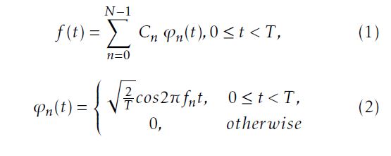
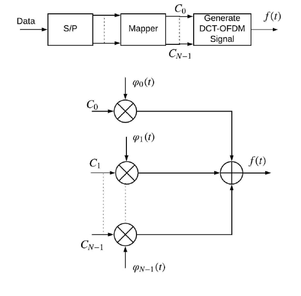
Figure 1: Block diagram of DCT-OFDM signal generator
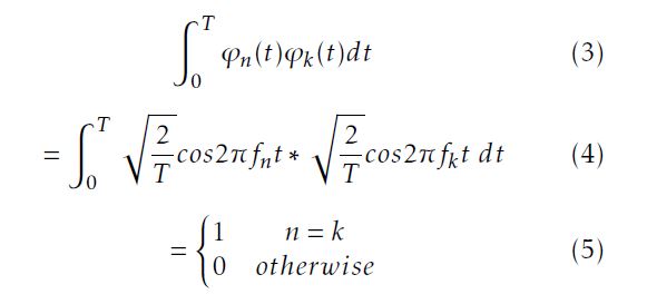
The cosinusoidal function ϕn(t) is the nth orthogonal signal with frequency fn = n/2T and repersents the nth subcarrier. The subcarrier spacing is 1/2T . The subcarriers are orthonormal over 0 ≤ t ≤ T = NTs. That is,
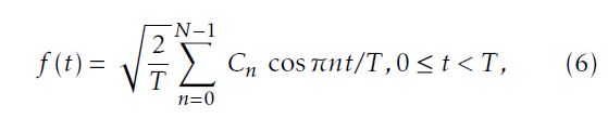
The time duration of the OFDM symbol is T = NTs; Ts is the time duration of DCT-OFDM symbol. It is noted that Ts = kTb and M = 2k. Tb denotes the bit duration. Cn(n = 0,1,..,N − 1) are N independent data symbols obtained from MPAM signal constellation. The DCTOFDM signal can thus be represented by
3 DCT-OFDM Signal with Phase Modulation
The phase modulated bandpass signal can be represented by
s(t) = Accos(2πfct +φ(t)) (7)
Where Ac and fc are the carrier amplitude and frequency. The phase in (7) is proportional to f (t) and is given by
φ(t) = hpf (t) (8)
where hp is the modulation index.
In DCT-OFDM system, f (t) is real for MPAM mapper [9]. The advantage of DCT-OFDM system with phase modulation is that the transmitted signals have peak and average powers the same and hence, their PAPR is 0 dB. Figure 2 shows a comparison of instantaneous powers of DCT-OFDM and CE-DCT-OFDM signals.
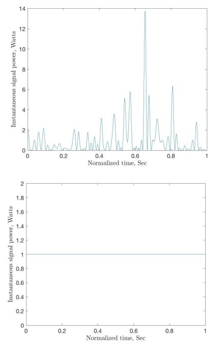 Figure 2: Instantaneous signal power: (a) DCTOFDM signal and (b) CE-DCT-OFDM signal.
4 CE-DCT-OFDM Transmitter
The block diagram of CE-DCT-OFDM transmitter is shown in Figure 3. The output of the system can be written as:
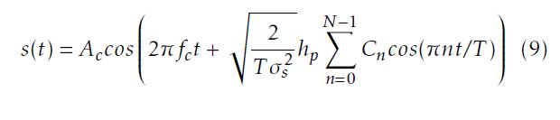 where 0 ≤ t ≤ T , Ac is the signal amplitude and fc is the carrier frequency. σs2 = (M2−1)/3 is the variance of the data symbols [16]. {Cn} are MPAM data symbols, Cn∈ {±1,±3,··· ,±(M − 1)} for all n. The message signal is given by: f (πnt/T ). The R T 2dt/T = A2c/2 and average power of s(t) is Ps = 0 s(t) the signal energy is Es = PsT = A2cT /2. For k bits of information per symbol per transmission, the average bit energy is Eb = A2cT /2N log2M = A2cT /2Nk.
4.1 Bandwidth Considerations
Phase modulated signals are complex to analyze for their bandwidth. However, simple observations can be used to get rough idea about the bandwidth of CEDCT-OFDM signals. Using Maclaurin series, the PM signal described in equation (7) can be written as
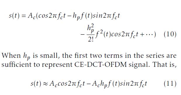 This represents the narrowband case and the bandwidth of the signal is at least 2W, where W is the bandwidth of f (t). As hp becomes larger, the bandwidth of the signal broadens. A useful expression for bandwidth of the signal is given by the rootmean-square (RMS) bandwidth [18] which is equal to max(2hp,2)WHz. The bandwidth of the message signal f (t) is
W = (N/2T )Hz
4.2 BER Analysis over AWGN Channel
The CE-DCT-OFDM receiver consists of a phase demodulator followed by the standard DCT-OFDM demodulator to recover the transmitted data symbols as shown in Figure 4. Each block will be analyzed below.
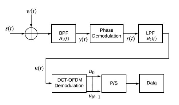
Figure 4: Block diagram of CE-DCT-OFDM receiver
4.2.1 Phase Demodulation
The noise w(t) is modelled as additive white Gaussian with zero mean and power spectral density N0/2. The received signal s(t)+w(t) is fed to a BPF with transfer function H1(f ) shown in Figure 5.
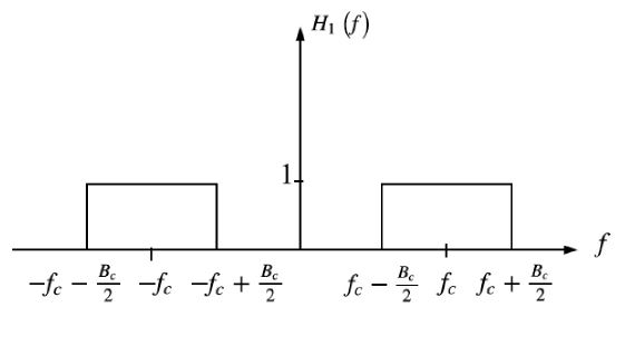 Figure 5: Ideal bandpass filter characteristic
The filter has a center frequency fc and bandwidth B. It is noted that only a negligible amount of input signal power lies outside the frequency band fc −B/2 ≤ |f | ≤ fc +B/2. The bandwidth B is in excess of twice the message bandwidth W by an amount that depends on the deviation ratio of the signal s(t). Thus, it is noted that the BPF allows the CE-DCT-OFDM signal without any distortion. The filtered narrow band noise n(t) can be represented as
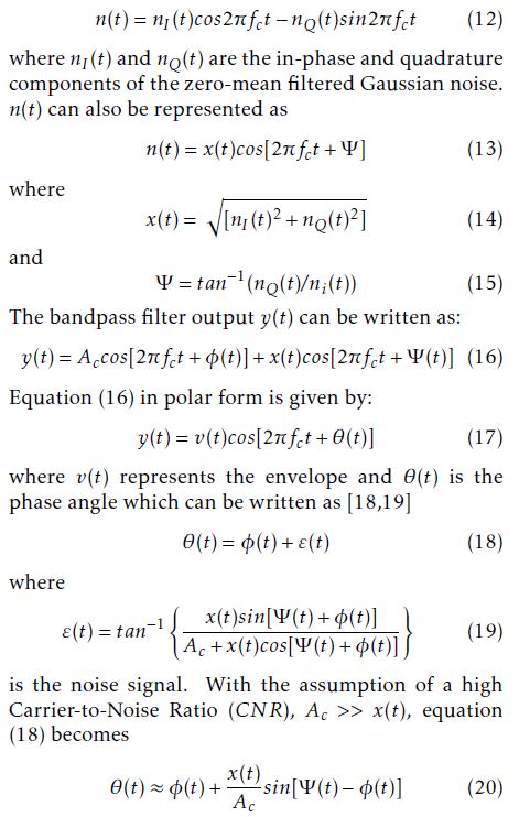
The output of the phase demodulator is given by

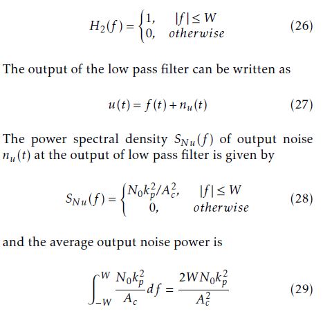
The phase demodulator output is applied to a low pass filter of bandwidth equal to message bandwidth W. It is used to pass the message signal and reject out of band noise from nd(t). The ideal transfer function of the filter is
4.2.2 DCT-OFDM Receiver
The DCT-OFDM receiver, as depicted in Figure 4, is composed of two stages: a demodulator and a detector. The demodulator projects the incoming signal using orthonormal bases and generates a vector whilst the detector applies detection algorithm to estimate the transmitted information symbols.
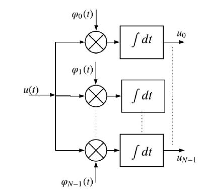 Figure 6: DCT-OFDM signal demodulation using correlators
The input to the bank of correlators (DCT-OFDM demodulator) in Figure 6 is the signal u(t). The output of the demodulator is the vector u¯. The j-th element of u¯, can be expressed as:
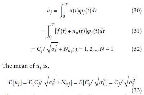
where Cj ∈ {±1,±3,…,±(M − 1)}.
The mean is independent of the noise. However, the variance of uj is dependent on noise and is given by:
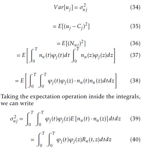
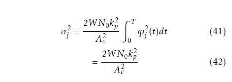
where Rnu(t,z) is the autocorrelation function of the noise process. The variance of uj can be shown to be given by:
4.2.3 Probability of Bit Error
The symbol error rate (SER) can be shown to be given by [21]:
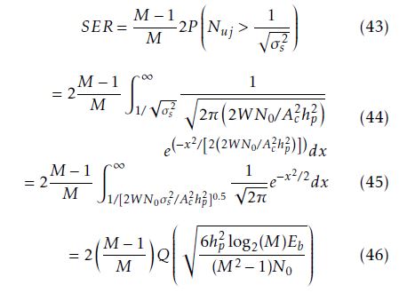
It is noted that for hp = 1, (46) represents the SER for MPAM system [21]. For high CNR, the only significant symbol errors are those that occur at adjacent signal levels. The BER of CE-DCT-OFDM system, thus, can be approximated as [21]
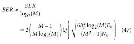
The BER performance given by (47) is a function of Eb/N0, signal-to-noise ratio, hp, modulation index, and M, the number of amplitude levels in the MPAM mapper in the CE-DCT-OFDM system. The performance of CE-DCT-OFDM system with hp = 0.7 for various values of M are illustrated in Figure 7, which shows that BER increases as M increases for fixed value of modulation index. For example at BER = 10−5 and hp = 0.7, the SNR required for M = 16 is 14 dB more than that required for M = 4.
Figure 8 depicts BER performance of CE-DCTOFDM system for 16-PAM mapper for hp = 0.3,0.7 and 1.2. It is observed that BER decreases as hp increases for a fixed value of SNR. For example at BER = 10−5 the SNR required for hp = 0.3 is 12 dB more than that required for hp = 1.2. The BER performance of the system can be controlled by varying h and M as shown in Figure 9. For example, the system with M = 16 and hp = 1.7 outperforms the system with M = 4 and hp = 0.2 by nearly 9 dB at BER = 10−5.
Figure 10 compares simulation results to theoretical BER given by (47) for CE-DCT-OFDM system using N = 64 subcarriers, and M = 4. For Eb/N0 greater than 15 dB, and for a small modulation index hp = 0.1, simulation result is nearly the same as theoretical result. For large modulation index, for example hp = 0.8, the theoretical BER is not as accurate as simulation result but still is within 1 dB of the former.
For the traveling-wave tube amplifier (TWTA) model, BER performance of CE-DCT-OFDM system is compared with that of DCT-OFDM system. The undesirable effects of TWTA nonlinearities can be reduced by increasing the input power backoff (IBO). For a given DCT-OFDM signal, we need to adjust the average input power so that the peaks of the signal are rarely clipped. That is, we will have to apply an IBO to the signal prior to amplification. Computer simulations are used to study the performance of the systems using nonlinear TWTA with various IBO levels. Figure 11 compares BER performance of 64 subcarrier 8PAM CE-DCT-OFDM system and 8-PSK DCT-OFDM system with TWTA using IBO of 0 dB, 8 dB and 12 dB. At high SNR, CE-DCT-OFDM system provides significant performance improvement due primarily to the 0 dB backoff. The DCT-OFDM system with 0 dB IBO has an error floor at BER of 0.09. At the BER 10−3, the IBO that results in the best DCT-OFDM system performance is 12 dB, with Eb/N0 = 16 dB. However, the CE-DCT-OFDM system achieves this BER= 10−3 with Eb/N0 = 12 dB which implies an advantage of 4 dB.
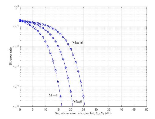 Figure 7: BER performance of CE-DCT-OFDM system over AWGN channel, as a function of M for hp = 0.7
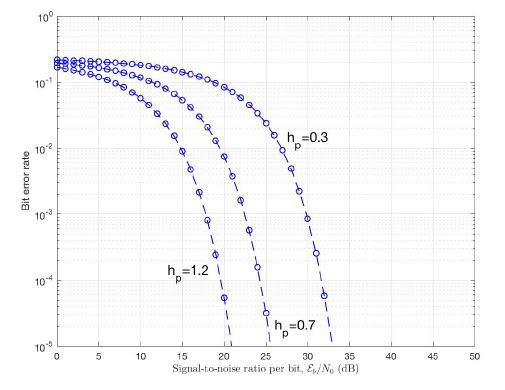 Figure 8: BER performance of CE-DCT-OFDM system over AWGN channel, as a function of hp for M = 16.
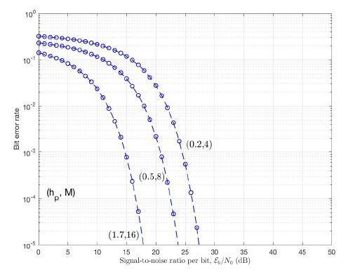 Figure 9: BER performance of CE-DCT-OFDM system over AWGN channel, as a function of (hp, M).
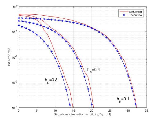 Figure 10: BER performance of 64 subcarrier CEDCT-OFDM system with M = 4 over AWGN channel, as a function of hp.
 Figure 11: Comparison of 64 subcarrier 8-PAM CE-DCT-OFDM and DCT-OFDM systems for model TWTA for various of IBO.
5 Performance over Fading Channels
The received CE-DCT-OFDM signal over a fading channel can be expressed as:
r(t) = h(t) ∗ s(t)+n(t) (48)
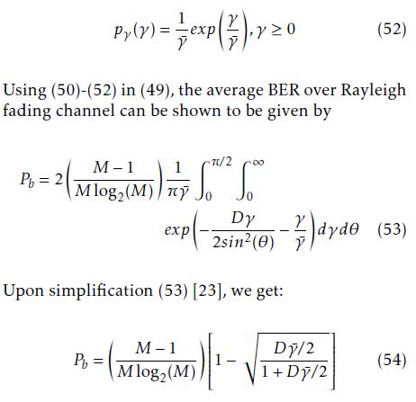
where h(t) represents the impulse response of the fading channel given by h(t) = αδ(t). The instantaneous SNR per bit and the average SNR per bit can be represented as γ = α2Eb/N0 and γ¯ = Enα2oEb/N0, respectively. To obtain the bit error rate (Pb) of CE–DCTOFDM system over such a fading channel, the conditional BER is averaged over the Probability Density Function (PDF) of γ and can be written as [22]:
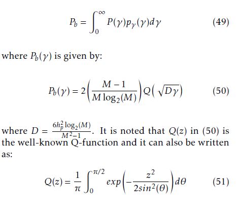
5.1 Rayleigh Fading Channel
For Rayleigh fading channel, the PDF of γ is given by [22]:
The BER given by (54) for CE-DCT-OFDM system over Rayleigh fading channel is a function of hp, modulation index, M, number of levels in MPAM, and Eb/N0, signal-to-noise ratio. The BER of CE-DCTOFDM system for M = 4 is plotted as a function of hp, and Eb/N0 as shown in Figure 12. It is observed that BER increases as hp decreases for a fixed value of SNR. For example at BER = 10−5 the SNR required for hp = 0.7 is 7 dB more than that required for hp = 1.5.
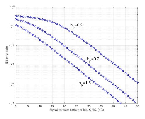 Figure 12: BER performance of CE-DCT-OFDM system over Rayleigh fading channel, as a function of hp for M = 4.
5.2 Ricean Fading Channel
For the Ricean fading channel, the PDF of γ is given by [22]:
The BER given by (57) is a function of hp, M, K, Rice distribution parameter and Eb/N0. The BER performance K = 7 dB and M = 4 is illustrated in Figure 13, are a function of hp. It observed that there is improvement in BER as hp increases, for example at BER= 10−5 the SNR required for hp = 1.5 is 17 dB less than that required for hp = 0.2.
The effect of parameter K on BER performance is illustrated in Figure 14, for M = 4 and hp = 0.5 . It is noted that the BER decreases as K increases, for example at BER = 10−5 and hp = 0.5 the SNR required for K = 2 dB is 30 dB more than that required for K = 18 dB.
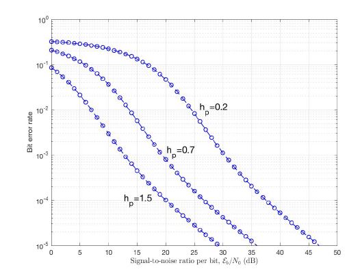 Figure 13: BER performance of CE-DCT-OFDM system over Ricean fading channel, as a function of hp for M = 4.
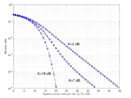 Figure 14: BER performance of CE-DCT-OFDM system over Ricean fading channel, as a function of K for M = 4 and hp = 0.5.
6 Conclusions
A generalized description of CE-DCT-OFDM system is presented. In this system, phase modulation is used to eliminate the problem of PAPR. BER analyses of this system over AWGN and flat fading channels are presented and closed-form expressions for BER have been obtained. Improved BER performance is seen with increased value of modulation index at fixed transmission power. It is also observed that BER performance can be controlled by varying hp and M as well. Simulation performance of CE-DCT-OFDM system over AWGN channel is also presented and compared with theoretical results. The results show that for a small modulation index, simulation result is nearly the same as theoretical result. With nonlinear the results show that CE-DCT-OFDM system has better BER performance than the conventional DCTOFDM system when TWTA amplifier is used.
Conflict of Interest
The authors declare no conflict of interest.
Acknowledgment
The first author would like to gratefully thank the Islamic University of Madinah and the ministry of higher education in Saudi Arabia for their support and scholarship.
- Rayan H. Alsisi, Raveendra K. Rao, ”Performance of constant envelope DCT based OFDM system with M-ary PAM mapper in AWGN channel,” IEEE International Systems Conference (SysCon), pp.1-7, Montreal, April 2017. http://ieeexplore.ieee.org/document/7934716/
- H. Han and J. H. Lee, ”An overview of peak-to-average power ratio reduction techniques formulticarricer transmission,” IEEEWireless Commun., vol.12, no.2, pp.56-65, April 2005. http://ieeexplore.ieee.org/document/1421929/
- Gi Hyun Kim, Honey Durga Tiwari, Chan Mo Kim, Yong Beom Cho, and Younggoo Kwon, ”Implementation of DCT based OFDM system,” International SoC Design Conference, IEEE, vol.2, pp.41-44, Busan, November 2008. http://ieeexplore.ieee.org/document/4815679/
- Tang and D. Mandyam,”Performance of OFDM modem with alternative basis functions, ” IEEE Radio and Wireless Symposium, pp.551-554, San Diego, October 2006. http://ieeexplore.ieee.org/document/1615216/
- Mandyam, ”Sinusoidal transforms in OFDM systems, ” IEEE Trans. On Broadcasting, vol.50, no.2, pp.172-184, June 2004. http://ieeexplore.ieee.org/document/1304952/
- Merched, ”On OFDM and single carrier frequency domain systems based on trigonometric transforms,” IEEE Signal Processing Letters, vol.13, no.8, pp.473-476, August 2006. http://ieeexplore.ieee.org/document/1658060/
- Al-Dhahir, H. Minn, and S. Satish, ”Optimum DCT-based multicarrier transceivers for frequency-selective channels,” IEEE Trans. Commun., vol.54, no.5, pp.911-921, May 2006. http://ieeexplore.ieee.org/document/1632105/
- Satish, N. Al-Dhahir, and H. Minn, ”A DCT-Based Broadband Multicarrier Transceiver,”, SoutheastCon, Proceedings of the IEEE, pp.175-180, Memphis, 2006. http://ieeexplore.ieee.org/document/1629345/
- Tan and G. L. Stuber, ”Constant Envelope Multi-Carrier Modulation,” in Proceedings of IEEE Military Communications Conference, vol.1, pp.607-611, Anaheim, October 2002. http://ieeexplore.ieee.org/document/1180513/
- Tsai and G. Zhang, ”Orthogonal Frequency Division Multiplexing with Phase Modulation and Constant Envelope Design,” in Proc. of IEEE Milcom, pp.2658-2664, Atlantic City, October 2005. http://ieeexplore.ieee.org/document/1606068/
- A. Wilkinson, A.E. Jones, ”Minimization of the Peak to Mean Envelope Power Ratio of Multicarrier Transmission Schemes by Block Coding,” IEEE VTC, pp.825-829, Chicago, July 1995. http://ieeexplore.ieee.org/document/504983/
- S. Krongold and D. L. Jones, ”An active-set approach for OFDM PAR reduction via tone reservation,” IEEE Trans. Signal Processing, vol.52, no.2, pp.495-509, February 2004. http://ieeexplore.ieee.org/document/1261335/
- Armstrong, ”Peak-to-average power reduction for OFDM by repeated clipping and frequency domain filtering,” IEE Electron. Lett., vol.38, no.5, pp.246-247, February 2002. http://ieeexplore.ieee.org/document/990223/
- -D. Chung and S.-M. Cho, ”Constant-envelope orthogonal frequency divisionmultiplexing modulation,” APCC/OECC Conference, vol.1, pp.629-632, Beijing, October 1999. http://ieeexplore.ieee.org/document/824966/
- Pacheco and D. Hatzinakos, ”Error rate analysis of phasemodulated OFDM (OFDM-PM) in AWGN channels,” IEEE International Conference on Acoustics Speech and Signal Processing Proceedings, pp.IV337-IV-340, Toulouse, May 2006. http://ieeexplore.ieee.org/document/1660974/
- Steve C Thompson, Ahsen U. Ahmed, John G. Proakis and James R. Zeidler, ”Constant Envelope OFDMPhase Modulation: Spectral Containment Signal Space Properties and Performance,” IEEE MILCOM, pp.1129-1135, Monterey, 2004. http://ieeexplore.ieee.org/document/1495013/
- C. Thompson, J. G. Proakis, and J. R. Zeidler, ”Constant Envelop Binary OFDM Phase Modulation,” IEEE MILCOM, pp.621-626, Boston, October 2003. http://ieeexplore.ieee.org/document/1290175/
- G. Proakis and M. Salehi, Communication Systems Engineering. New Jersey: Prentice-Hall, 1994.
- Zeimer and W. Tranter, Principles of Communications: Systems, Modulation, and Noise, 4th ed. New York: John Wiley, 1995.
- J. Downing, Modulation Systems and Noise. Prentice-Hall, 1964.
- G. Proakis, Digital Communications, 4th ed. New York: McGraw- Hill, 2001.
- K. Simon and M.-S. Alouini, Digital Communication over Fading Channels. New York: John Wiley and Sons, Inc., 2000.
- S. Gradshteyn and I. M. Ryzhik, Table of Integrals, Series, and Products, vol. 6, California, Academic Press, 2000.