Approximate method of analysis of log-periodic antennas with in-phase currents

Adv. Sci. Technol. Eng. Syst. J. 3(1), 239–243 (2018);
 DOI: 10.25046/aj030129
Log-periodic antennas have high electrical characteristics over a wide frequency range. The large length of the antennas is their significant disadvantage caused by the fact that each active region consisting of several radiators operates in a narrow frequency range. To extend this range, it is proposed to use radiators with concentrated capacitive loads, providing in-phase currents with a linear amplitude distribution law. An approximate calculation of the fields and directional characteristics of a complex multielement radiating structure is performed using a new method of electrostatic analogy based on the assumption that the ratio of emf in the radiator centers is equal to the charge ratio on the conductors of the electrically neutral system. The problem of optimization of considered antennas by methods of mathematical programming is formulated.
1. Introduction
The use of concentrated loads included along the axis of a linear antenna allows solving the synthesis problem, i.e., to obtain an antenna with required characteristics, more precisely with characteristics closest to required [1]. The special case of this problem – the creation of an antenna that provides a high level of matching in a wide frequency range and a maximum of radiation in a plane perpendicular to the axis of the radiator – has a great practical importance.
A conventional linear radiator does not satisfy these requirements. A reactive component of its input impedance is great everywhere except of a vicinity of a series resonance. When the length of a radiator arm is greater than ( is a wavelength), the radiation in the plane perpendicular to its axis decreases, since anti-phase segments form on the current curve.
The task of creating a wide-range radiator is to determine the types and quantities of loads that provide high characteristics of the antenna in the operating frequency range. This task was solved by applying concentrated capacitive loads (capacitors) installed along the axis of the radiator and forming an in-phase current with a given law of the amplitude distribution along the antenna. The solution was based on an understanding of the advantages of in-phase current distribution and Hallen’s hypothesis on the use of capacitive loads, the values of which vary along the radiator axis in accordance with a linear or exponential law. The chosen approach confirmed the Hallen’s hypothesis and demonstrated the effectiveness of the proposed approximate methods of calculating capacitive loads: the method of impedance long-line and the method of a long-line with loads. The loads calculated by these methods were used as the initial values for numerical solution of the problem by methods of mathematical programming.
Since the placement of concentrated capacitive loads along the radiator allows to obtain not only a high level of matching of the antenna with the cable, but also high directional characteristics in a wide frequency range, the application of these loads had been considered in radiators – first in a linear antenna and then in directional one.
It should be emphasized that the optimization problem, as a rule, is solved in two stages. At the first stage an approximate method of analysis, based on physical representations about the nature of the problem, is developing. At the second stage, approximate results are used as initial values for the numerical solution of the problem by methods of mathematical programming.
The proposed method of an approximate analysis of antennas characteristics allowed us to calculate the directional patterns of radiators with a given current distribution and to compare performances of antennas, in which various laws of current distribution are realized. This is, firstly, the linear metal antenna with a sinusoidal current distribution along its axis, and secondly, the linear antenna with an in-phase current and with a linear or exponential law of an amplitude distribution. Calculations show that the use of linear antennas with capacitive loads makes it possible to obtain in the wide frequency band the desired shape of the radiation pattern, which provides a substantial increasing the communication distance.
To evaluate this shape, a special parameter has been introduced – the pattern factor, equal to an average radiation level in a given range of vertical angles, for example, at angles from 60° to 90°. This parameter shows in fact what part of the signal is propagating along the earth’s surface, i.e., it is useful for increasing the communication distance. With the help of the proposed method, it is shown that the in-phase current distribution in linear and V-radiators provides not only a high level of matching, but also the high directivity and smooth variation of this directivity over a wide frequency range [2].
For an approximate calculation of the fields of complex multielement radiating structures, the method of electrostatic analogy was proposed. It is based on the assumption that the ratio of emf in the radiators centers is equal to the ratio of the charges located on the conductors of electrically neutral system. This allows proposing a simple and effective procedure of calculating directional characteristics of director and log-periodic antennas with concentrated capacitive loads. The calculation results confirm the possibility of increasing the frequency range of the director antennas and decreasing the length of the log-periodic antennas.
The results of applying this method to calculating the directional characteristics of director antennas are given in [3]. They are compared with the characteristics of director antenna, described in [4] and consisting from four metal elements: active radiator, reflector and two directors. When optimizing the metal antenna, the mathematical programming method was used. The application of the approximate method of electrostatic analogy to a metal antenna confirmed the results obtained in [4]. With the help of the presented procedure, it was shown also that in-phase current distribution in radiators of the director antennas provides the higher directivity in a wide frequency range.
The remainder of this paper is organized as follows. In Section II, the proposed method of analysis is applied to the calculation of fields and directional characteristics of an active region of the log-periodic antenna. The numerical results obtained in Section III for such antennas with in-phase currents show that the number of such regions can be substantially reduced. The section IV contains conclusions, which emphasize a theoretical interest and practical benefits of the work.
2. Method of Analysis
In accordance with a well-known method of analysis of a log-periodic antenna [5], we consider an active region of this antenna, consisting of three radiators (Fig. 1), and find fields of these radiators when emf e is located in the center of the middle radiator. In accordance with Kirchhoff’ law other generators must be short-circuited. As shown in [5], this means that emf’s in the centers of other radiators and at the ends of sections of a two-wires distributive long line in the points of these radiators location are shorted also. We regard that the arm length of the middle radiator is , the arm length of the left (longer) radiator is equal to , and the arm length of the right (shorter) radiator is where is a denominator of a geometric progression, according to which the radiators’ dimensions are changed. A magnitude is the other antenna parameter, equal to where is an angle between an antenna axis and a line passing through radiators ends. The value is the number of wavelengths between the half-wave radiator and the smaller neighboring radiator: .
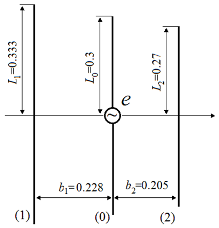 Figure 1: Antenna of three radiators
Respectively is equal to . As stated in [6], generalization of information in the literature leads to the conclusion that the minimum changes in the electrical characteristics of the log-periodic antenna with metal dipoles within the frequency range from f to occur when We regard that this relation is valid for the considered antenna and that value for certainty is equal to 0.9. Then , , , , .
As already mentioned, we use the method of electrostatic analogy of two structures (of currents and charges), located on the same conductors, as an approximate method. We are assuming that the ratio of emf’s in the radiator centers is equal to the ratio of charges located on these conductors. The positive charge, equal to , is placed on the conductor 0 (active radiator). The charges of other conductors i are negative. They are equal to , and their sum is equal to , i.e., the sum of all charges is zero, and the conductors form an electrically neutral system. In this system
![]() where is the partial capacitance between conductors 0 and i (see, for example, [7]). From (1) it follows that the charges of the conductors i are directly proportional to the partial capacitances between these conductors and the conductor 0. The mutual capacitance per unit length of two parallel infinitely long conductors of the radius a is equal to
where is the partial capacitance between conductors 0 and i (see, for example, [7]). From (1) it follows that the charges of the conductors i are directly proportional to the partial capacitances between these conductors and the conductor 0. The mutual capacitance per unit length of two parallel infinitely long conductors of the radius a is equal to
![]() where is the medium permittivity, and is the distance between the conductors. Multiplying this value into the conductor length, we find in a first approximation the partial capacitance between these conductors.
where is the medium permittivity, and is the distance between the conductors. Multiplying this value into the conductor length, we find in a first approximation the partial capacitance between these conductors.
We divide the active radiator (conductor 0) into two parallel conductors (with numbers 01 and 02), and the resulting structure of four conductors into two circuits: conductors with numbers 01 and 1 in the first scheme, and conductors with numbers 02 and 2 in the second scheme. In accordance with the method of electrostatic analogy of the two structures, i.e., in accordance with the physical content of the problem, we will assume that the ratio of the emf in the centers of the wires 01 and 02 is equal to the ratio of the partial capacitances and , i.e., .
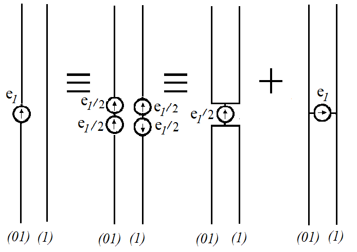 Figure 2: Successive transforming a structure of two parallel vertical conductors
Fig. 2 demonstrates a scheme for successive transforming a structure of two parallel vertical conductors (01 and 1), one of which is excited at the center, into a structure consisting of a two-conductor dipole and two open transmission lines. The scheme is based on the theory of a folded antenna (see for example, [1]). As can be seen from this figure, the current at the center of each dipole conductor and the current at the same point of each transmission line are respectively equal
![]() where is the input impedance of this dipole, is the input impedance of each long line. Accordingly, the current of the upper arm of the conductor 01 is equal to the difference of these currents, and the current of the lower arm of the conductor 01 – to the sum:
where is the input impedance of this dipole, is the input impedance of each long line. Accordingly, the current of the upper arm of the conductor 01 is equal to the difference of these currents, and the current of the lower arm of the conductor 01 – to the sum:
![]() The current of the upper arm of the conductor 1 on the contrary is equal to the sum of these currents, and the current of the lower arm of the conductor 1 – to their difference. The field amplitude and phase value of each radiator depend on its structure and location in an antenna. If the radiator arm is manufactured as the straight metallic wire, the current along it is distributed by the sinusoidal law
The current of the upper arm of the conductor 1 on the contrary is equal to the sum of these currents, and the current of the lower arm of the conductor 1 – to their difference. The field amplitude and phase value of each radiator depend on its structure and location in an antenna. If the radiator arm is manufactured as the straight metallic wire, the current along it is distributed by the sinusoidal law
![]() Here z is a coordinate along the radiator axis, is the current in its center, k is the propagation constant. In this case the far field of the radiator is equal to
Here z is a coordinate along the radiator axis, is the current in its center, k is the propagation constant. In this case the far field of the radiator is equal to
![]() where , R is the distance to the observation point. If concentrated capacitive loads located along the radiator axis allow realizing in it the in-phase current with an amplitude, distributed along this axis by the linear law,
where , R is the distance to the observation point. If concentrated capacitive loads located along the radiator axis allow realizing in it the in-phase current with an amplitude, distributed along this axis by the linear law,
![]() the far field of the radiator (see [2]) is equal to
the far field of the radiator (see [2]) is equal to
![]() Consider an impact of the radiator location on the far field of the antenna by way of a specific example of the director antenna, shown in Fig. 1. The arm length of the middle (active) radiator is equal to 0.3 м, i.e., the wave length of the first (series) resonance is equal to 1.2 м. Radii of all conductors are the same and are equal to 0.001м. The magnitude is 0.9.
Consider an impact of the radiator location on the far field of the antenna by way of a specific example of the director antenna, shown in Fig. 1. The arm length of the middle (active) radiator is equal to 0.3 м, i.e., the wave length of the first (series) resonance is equal to 1.2 м. Radii of all conductors are the same and are equal to 0.001м. The magnitude is 0.9.
It is obvious that the maximal radiation of the antenna should be directed to the right, toward the radiator 2. Since the radiator 1 is located from the left of the active radiator 0, at a distance from it, its field lags behind the field of the active radiator, first on in phase, that is by the time interval of the propagation of the signal from the active radiator to the passive radiator 1, and, secondly, by in phase, i.e., by the time of the signal propagation in the opposite direction, from the radiator 1 to the active radiator (signal of the wire 1, radiated at an angle , must come to the active radiator at the same angle , i.e., it must pass the distance , and not the distance . The total change in phase is equal to . Similarly, in the case of radiator 2, this phase change is equal to
The total field of the antenna structure shown in Fig. 1 with in-phase current distribution at angle on the base of aforesaid may be written in the form
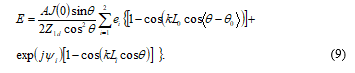 The directivity magnitude is determined by the expression
![]()
where is the interval between neighboring values , N is the number of these intervals between and .
3. Examples of Calcultations
The results of calculating the directivity magnitude for the structure, shown in Fig. 1, are given in Fig. 3 depending on an electrical length of the arm of the active radiator. The curve 1 demonstrates the directivity of the structure with in-phase currents in all its elements. The directivity of the structure with sinusoidal currents is given for comparison by means of the curve 2. The radiators with concentrated capacitances allow ensuring a high level of matching with a cable in a range with a frequency ratio of the order 10. Therefore, graphics are made so that to show the structure directivity in a range from to .
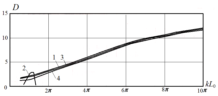 Figure 3: Directivity of structures of three radiators
Radiation of neighboring elements of log-periodic antenna with the arm length 0.27 m and 0.333 m respectively requires calculating fields in the structures presented in Fig. 4a and 4b. Results of these calculations are given in Fig. 3: curve 3 corresponds to Fig. 3a, curve 4 – to Fig. 3b. The directivity magnitudes in Fig. 3 for specific values correspond to the same frequencies, i.e., the same values of correspond to the elements of equal length in the all three schemes (for example, to the elements with the arm length 0.3 m). Fig. 3 shows that the directivity magnitudes at the same are close to each other. This is natural, since the directivity in each scheme increases slowly with increasing frequency. Small increasing the active radiator length causes at the same the small increase of the resonant wavelength, i.e., the small decrease of the resonance frequency and the directivity.
The obtained results show that each active radiator with in-phase current included in the structure of the log-periodic antenna provides high radiation directivity in a wide frequency range. Neighboring radiators have similar directivity magnitude. The direction of the radiation is the same. A signal propagates along the distributive line from short elements to the long dipoles (in Figures 1 and 4 to the left), the radiated signal propagates in the opposite direction. The total path difference is quite large. For example, for the signals radiated by a half-wave radiator and a smaller neighboring radiator it is equal to 0.38 , i.e., it is close to a half wavelength. Crossing wires of the distributive line in an interval between the elements permits to reduce dramatically this path difference.
Known log-periodic antenna with sinusoidal current distribution along the radiators have a property of automatic currents “cut-off”, i.e., a separate antenna section (active region) radiates a signal in a narrow frequency band. Outside this band, outside the borders of the active region the signal decays rapidly. Wide frequency range is provided by a large antenna length, which is equal to the sum of the lengths of the active regions. Attempts to reduce the antenna length by disturbing a geometric progression and increasing a radiators number lead to a small dimension decrease and a sharp deterioration of electrical characteristics. The more effective methods are firstly a two-fold use of each active region by an application of linear-spiral radiators and secondly an employment of an asymmetrical log-periodic antenna with coaxial distribution line [6]. These methods allow decreasing the antenna length by 25-30%.
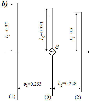 Figure 4: Structures of smaller (a) and greater (b) neighboring radiators
Replacement of the straight metal radiators by the radiators with concentrated capacitive loads allows obtaining a high directivity in a wide frequency range, using a simple structure of three radiators. Increasing the radiators number in the structure must allow to dramatically increasing its directivity.
4. Conclusion
In this work the following results are obtained:
1) The method of electrostatic analogy is proposed for calculating fields of complex multielement antennas. It is based on an assumption that a ratio of emf in radiators centers is equal to a ratio of charges located on conductors of an electrically neutral system. This method had been used for calculating directional characteristics of log-periodic antennas.
2) The given procedure permitted to compare the directional characteristics of log-periodic antennas with sinusoidal and in-phase current distribution in simple radiators. It was shown that replacement of the metal radiators by the radiators with concentrated capacitive loads allows providing, using a few radiators, the high directivity in a wide frequency range, i.e., decreases sharply the antenna length. Increasing radiators number must allow increasing substantially the antenna directivity.
Results obtained by means of the method of electrostatic analogy may be used for solving optimization problem log-periodic antennas by methods of mathematical programming.
- B. M. Levin. Antenna engineering. Theory and problems. A science publishers book: London, New York, 2017.
- B. M. Levin. “Directional properties of linear and V-antennas” in 11 Intern. Confer. ICATT’17. Kiev (Ukraine), 2017, pp.104-109.
- B. M. Levin. “Director antennas with in-phase currents” in 11 Intern. Confer. ICATT’17. Kiev (Ukraine), 2017, pp.110-113.
- A. F. Chaplin, M. D. Buchazky, M. Yu. Mihailov. “Optimization of director-type antennas”. Radiotechnics, 1983, no. 7, pp. 79-82 (in Russian).
- R. L. Carrel. “The design of log-periodic dipole antennas. IRE Intern. Convention Record, part 1, 1961, pp. 61-75.
- A. F. Yakovlev, A. E. Pyatnenkov. Wide-band directional antennas arrays from dipoles. S.-Petersburg: Research center of communication, 2007 (in Russian).
- Yu. Ya. Iossel, E. S. Kochanov, M. G. Strunsky. Calculation of Electrical Capacitance. Leningrad: Energoisdat, 1981 (in Russian).
No related articles were found.