Medium Voltage Microgrid Test Setup and Procedures Implemented on a Real Pilot Project
 , Marcos Aurelio Izumida Martins 1, Cesare Quinteiro Pica 1, Nilo Rodrigues 2
Adv. Sci. Technol. Eng. Syst. J. 3(1), 234–238 (2018);
 DOI: 10.25046/aj030128
This paper presents various concepts related to the application of a microgrid pilot project in a residential condominium at Fortaleza / CE – Brazil, such as battery energy system, renewable and distributed generation, islanding recloser and all different units using interface based on power electronics. This papers main objective is to create information about microgrid operation and the interaction between its main equipment, such as power converters, utility energy distribution system and control units responsible for algorithms and changes in microgrids operation mode. This information is important for understanding the need for a test setup construction. To perform the test procedures, a temporary setup in a controlled environment within the microgrid is proposed. During the test periods, intentional power outages are required to evaluate the operating mode switching on each unit. The test setup described in this paper aims to mitigate the tests effects on other residential units inside the condominium.
1. Introduction
Typical electric power systems are known to operate by transmitting energy in bulk from large generating plants over long distances to large load centers. With the introduction of distributed generation and the growing evolution of power electronics for the renewable generation sources of electricity, such as solar and wind, this scenario of operation has been changing gradually, leaving behind the centralized form of generation and becoming now decentralized, producing energy closer to consumers [1, 2].
In this context, microgrids present a new concept of power generation and distribution. Microgrids are utility power grid subsystems composed of a set of distributed energy resources, controllable electric loads, energy storage elements and power control system. Microgrid main characteristic is the ability to operate in island conditions, i.e., operate isolated from the main electricity distribution grid preserving an energy quality for microgrid connected consumers [3-5].
In addition to both connected and islanded modes, this microgrid, under analysis, presents a third operation mode referred to as Maintenance Mode. This operation mode is activated when a fault, such as short circuit, happens inside the microgrid, and consequently making it impossible to operate islanded. Therefore, maintenance mode becomes essential while aiming towards a safe microgrid operation. Recent studies [6, 7] also described the importance of such mode and its benefits for microgrid operations.
While in maintenance mode, the microgrid cannot be powered by any of its distributed energy resources (DER), i.e., the central energy storage (grid-forming power converter) and its internal sources of distributed generation (grid-feeding power converter) are unable to generate energy. Maintenance mode is also triggered with a power distribution company request, followed by command from the operation center, due to maintenance in the local medium voltage distribution grid, as it is procedure to disable the microgrid and ensure a complete absence of power at the condominium internal distribution grid.
To perform real tests of the control system operation mode switching and interaction with the equipment, a test setup for the pilot microgrid is proposed, aiming to mitigate the impact on consumers loads. In this paper, the microgrid project in analysis will be presented first and then the proposed test setup and procedures.
2. Microgrid Architecture
This microgrid under study is located in a residential condominium at Fortaleza / CE – Brazil. The condominium is connected to the utility through medium voltage grid.
The Microgrid is divided into several units according to their characteristics and devices. This unit delimitation allows a better understanding of microgrid operation. Those units are shown in Figure 1.
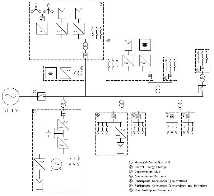 Fig. 1. Architecture of the real microgrid pilot project.
The main microgrid units are presented as it follows:
2.1. Central Energy Storage
This unit is composed by an energy storage system along with its power conversion and control devices. With a storage capacity of 105kWh and 250kW of power, this system is able to supply power for the microgrid while operating in islanded mode [8]. Figure 2 displays a simple electric diagram for this unit.
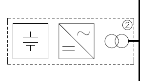 Fig. 2. Central Energy Storage.
The central storage system features a lithium-ion battery bank, grid-forming power converter, 380/13800 V power transformer, switchgear and their respective control and protection equipment.
During islanded mode, this unit function is to provide power for the loads and a voltage reference for all renewable distributed generation. While operation at connected mode, this unit is recharged and can also be discharged providing grid support services.
2.2. Consumers Units
Microgrids consumers are the systems main loads. They are strategically chosen residential consumers with distributed generation resources and some with local storage systems.
They are subdivided into Participant Consumers and Non Participant Consumers. Whilst operating in connected mode, both participant and non-participant act as loads for the system. During islanded operation, non-participant consumers are disconnected through smart meters. Therefore, only participant consumers remain connected at microgrid [8].
Figures 3 and 4 displays a simplified electrical diagram of those participant consumers. They are equipped with demand-response devices, solar generation, power inverters, smart meters, and some units are also equipped with a local storage system.
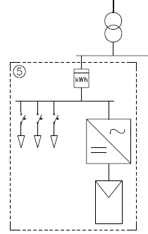 Fig. 3. Participant Consumers Units.
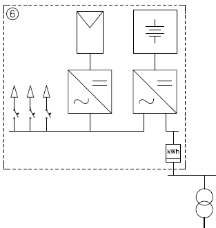 Fig. 4. Participant Consumers Units with a local storage system.
2.3. Club Unit
This residential condominium contains a club with common areas for its residents. The Club Unit (Figure 5) is also a microgrid consumer, however it has a larger distributed generations, composed with 24kWp of photovoltaic panels, as well as 7kW of wind generation.
Like the participating consumers, the Club is endowed with controllable loads through the demand-response devices. Another important detail is that this unit is connected at microgrid in medium voltage and has its own substation.
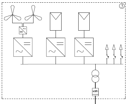 Fig. 5. Club Unit.
2.4. Condominium Entrance
This unit contains critical loads for condominium security and safety functions. Due to this fact, it is equipped with a diesel generator as a back-up unit.
A back-to-back converter is employed as a connection interface with the utility grid, allowing for smooth operation during power outage scenarios. Furthermore, this diesel generator can be used in a microgrid support scheme, relieving the system during a utility outage [8].
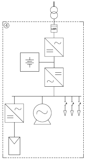 Fig. 6. Condominium Entrance.
This unit also has a solar generation system and controllable loads with demand-response devices as shown in Figure 6.
2.5. Microgrid Connection Unit
The Microgrid Connection Unit (Figure 7) consists of a medium voltage recloser and a set of control equipment for an energy outage detection in the distribution system, coordination of islanding and microgrid reconnection to the distribution system.
This unit is responsible for controlling the microgrid operation mode changes by informing other control units. It is also the communication interface with the utility grid SCADA (Supervisory Control and Data Acquisition) system.
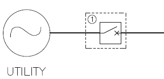 Fig. 7. Microgrid Connection Unit.
3. Microgrid Test Setup
In order to validate microgrid safe operation during its transitions through connected, islanded and maintenance modes, a power setup is proposed for conducting systemic tests (Figure 8).
The premise of this setup is to use the Club Unit area for real islanding, synchronization and reconnection microgrid tests. Since the Club Unit has a medium voltage connection, which is independent from the other condominium derivation line, any power supply interruption inside this area will not affect other microgrid units, reducing the inconvenience for all condominium residents.
As mentioned before, the Club unit has a larger amount of distributed generation and controllable loads. That can be used as a controlled test environment by simulating the residents homes energy consumption and generation. Thus, real tests of operation mode switching can be conducted in a safe way using the Club unit infrastructure.
In connected mode, the utility grid supplies the power for the loads and sets a voltage reference for the power electronics equipment of the generating units. The Central Energy Storage behaves like a grid-feeding power converter in this mode, only providing utility grid support when requested.
3.1. Islanding Tests
For islanding tests, the Microgrid Connection Unit (① in Figure 8) detects an outage in the distribution system due to under voltage protections. It then proceeds to disconnect the microgrid from the utility and sends a command to the Central Energy Storage, requesting a change in its mode of operation. The use of the temporary recloser (② in Figure 8) installed in the test setup input derivation is essential, in order to simulate an outage occurring when an intentional opening of this equipment is performed.
After disconnecting and receiving the command from the Microgrid Connection Unit, the Central Energy Storage operates as a grid-forming power converter, assuming the role of the main power supply of the microgrid and providing voltage reference for the generation interfaces.
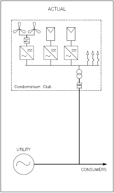
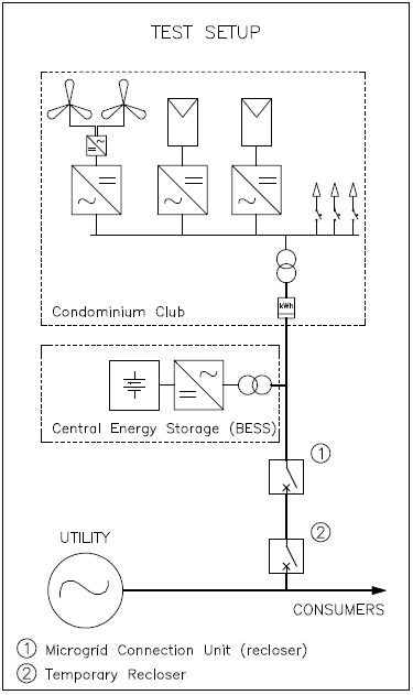 Fig. 8. Actual setup and Microgrid test setup.
3.2. Reconnecting Tests
When reconnecting the microgrid to the utility grid, the temporary recloser (② in Figure 8) is closed simulating the utility grid stable return after an outage.
The Microgrid Connection Unit detects the energy utility supply return while the Central Energy Storage synchronizes with the utility voltage reference. Microgrid is only reconnected to the main electricity distribution grid after synchronization is achieved.
Before the microgrid is connected to the utility grid, some of the indicators and parameters need to be checked, and the best time to close static switch should also be judged. This process is very important that can prevent the dangerous of transient phenomena during connecting the microgrid to utility grid. The good time to close the switch is when the voltage across the switch has to be very small (ideally zero), and the grid’s frequency is higher than the microgrid’s frequency. Because the current flowing through the switch is minimum, and the power flow direction is from utility grid to the microgrid in such a situation.
A safe and reliable grid-connection process will require to meet the following three conditions: a) the voltage through the static switch must be very small. b) microgrid operating frequency must be slightly smaller than the grid frequency. c) utility grid voltage must be ahead of the microgrid voltage [9].
3.3. Maintenance Tests
Maintenance mode is also tested in this setup with a request through utility operation center command. In such case, it must be verified that the Central Energy Storage is disconnected from the grid, not powering the microgrid when necessary.
Another advantage for this test setup is that all equipment employed will be used in the final installation. In this procedure it is possible to test the interaction between connected equipment in medium voltage, control system and power electronics interfaces. In addition, the Central Energy Storage is tested at its final installation place allows for other control and protection details to be verified.
4. Conclusions
In this work, the microgrid architecture on a pilot project at a residential condominium is presented, along with its main units, equipment and components according to its functionalities and technical characteristics.
Through the proposed test setup it is possible to obtain performance indicators on microgrid operating mode transitions and grid-forming power converter, as well as the integration between the control and protection equipment.
With the test setup execution, all operation modes shall be validated, along with transitions among them. The test results will improve the teams acknowledge around a correct microgrid functioning and a validation of its infrastructure and equipment.
Acknowledgment
The authors thank the Research Program and Technological Development of the electricity sector regulated by ANEEL and Enel Distribuição Ceará for the financial support to the project. This work is related to the project “Development Application of Pilot Microgrid Power Distribution with Distributed Generation and Commercial Operations Model” under PD- 0039-0073 / 2014 ANEEL.
- M.A. Antunes, S.M. Silva and B.J.C. Filho, “Análise e Operação de uma Microrrede de Energia Elétrica,” VI Simpósio Brasileiro de Sistemas Elétricos, 2016.
- Gang HU et al. “Study on Modeling and Simulation of Photovoltaic Energy Storage Microgrid” 4th International Conference on Information Science and Control Engineering, p.692-695, 2017.
- H. Lasseter, “MicroGrids,” IEEE Power Engineering Society Winter Meeting. Conference Proceedings (Cat. No.02CH37309), vol. 1, no. C, pp. 305–308, 2002.
- Daniel E. Olivares “A Centralized Energy Management System for Isolated Microgrids.” IEEE Transactions os Smart Grid, VOL. 5, July 2014.
- Benedetto Aluisio et al. “Embedding Energy Storage for Multi-Energy Microgrid Optimal Operation”, 2017.
- Sundari Ramabhotla et al. “Operation and Maintenance Cost Optimization in the Grid Connected Mode of Microgrid.” 2016 Ieee Green Technologies Conference,Kansas City, p.56-61, 2016.
- Richard B. Jones “How Reliable is your Microgrid: An insurer’s perspective on risk drivers for ditributed resources.”, Reston, July 2015.
- A.I. Martins et al., “Design and Implementation of a Microgrid Power Management Unit Using a Back-To-Back Converter in a Residential Condominium Connected at Medium Voltage,” COBEP SPEC IEEE Power Electronics Society, 2015.
- Meiqin Mao, Yinzheng Tao, Liuchen Chang, Yongchao Zhao and Peng Jin, “An intelligent static switch based on embedded system and its control method for a microgrid,” IEEE PES Innovative Smart Grid Technologies, Tianjin, 2012, pp. 1-6.