Effective Thermal Analysis of Using Peltier Module for Desalination Process

Adv. Sci. Technol. Eng. Syst. J. 3(1), 191–197 (2018);
 DOI: 10.25046/aj030122
The key objective of this study is to analyse the heat transfer processes involved in the evaporation and condensation of water in a water distillation system employing a thermoelectric module. This analysis can help to increase the water production and to enhance the system performance. For the analysis, a water distillation unit prototype integrated with a thermoelectric module was designed and fabricated. A theoretical model is developed to study the effect of the heat added, transferred and removed, in forced convection and laminar flow, during the evaporation and condensation processes. The thermoelectric module is used to convert electricity into heat under Peltier effect and control precisely the absorbed and released heat at the cold and hot sides of the module, respectively. Temperatures of water, vapour, condenser, cold and hot sides of the thermoelectric module and water production have been measured experimentally under steady state operation. The theoretical and experimental water production were found to be in agreement. The amount of heat that needs to be evaporated from water-vapour interface and transferred through the condenser surface to the thermoelectric module is crucial for the design and optimization of distillation systems.
1. Introduction
Salt water is about 97% of the world’s water, but less than 3% is fresh water. In this small fraction, only 0.3% of the fresh water is used by humans. Many places in the world, for example the developing countries, are facing water crises because of population growth and climate change [1-3]. Generating drinkable water from salt water (desalination) is one of the most important approaches to solve this issue without any serious impact on the environment [4-7]. Desalination can be achieved using two methods which are reverse osmosis technology and thermal distillation through evaporation and condensation processes [8-10].
Evaporation and condensation are fundamentally convection heat transfer processes involving phase change. When the temperature of water at given pressure is increased to the saturation temperature, water will evaporate. Similarly, condensation occurs when the temperature of a vapour is reduced below its saturation temperature. In the thermal distillation systems, control the evaporation and condensation rates lead to enhance the water production by increasing the water and vapour temperatures and decrease the condenser temperature. However, these processes consume energy and needs to enhance its performance [11-15].
There are various integrated technologies for water distillation systems, one of these is thermoelectric (TE) technology. Thermoelectric modules have no moving parts and a long life. They are noiseless, easy to control, and compact in size, consume a small amount of energy and so cause less pollution. The principle of the thermoelectric module is based on the Peltier, Seebeck and Thomson effects. The thermoelectric modules can be employed for refrigeration (Peltier), power generation (Seebeck) and temperature sensing (Thomson) [16-20]. The basic concept of thermoelectric modules is to convert thermal energy directly into electrical energy and vice versa. As a temperature gradient is established within a thermoelectric module, voltage difference is produced (under Seebeck mode) and a DC current will be created. As a DC current is applied within a thermoelectric module, temperature difference is established between the hot and cold sides of the module (under Peltier mode). The Peltier modules are employed in the thermal distillation systems to generate freshwater by using the cold side of the module to enhance water condensation. Recently, considerable amount of researches have been used thermoelectric technology to increase the water production rate and consequently enhance the system performance [21-28]. Hence, previous thermoelectric distillation systems are not comprehensive enough to properly analyse the evaporation and condensation processes under steady state operation.
This paper considers applying energy conservation to the system including the amount of thermal energy entering and leaving the system under steady state operation. This study aims to recognise the beneficial heat for water production and also governs the evaporation and condensation rates to become equilibrium under controlled conditions.
2. System Description
A designed water distillation system consists of an aluminium chamber placed a top water bath and one thermoelectric module placed between outer surface of the chamber and a water heat exchanger. The cold side of the thermoelectric module is mounted on the top aluminium surface as an inclined condenser, whereas the hot side of the module is attached to the water heat exchanger to enhance heat flow. Figure 1 shows the main parts of the system.
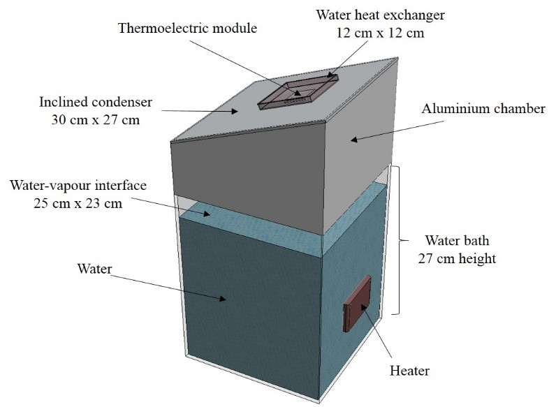 Figure 1. Schematic diagram of the main parts of the water distillation system.
3. Theoretical Model
Theoretical modelling of the water distillation system can be an effective tool for predicting system performance. A set of equations that describes convection heat transfer, fluid flow and phase change are employed to calculate the amount of heat involved in the evaporation and condensation processes and the rates of the evaporation and condensation in the system.
3.1. Assumptions
In the theoretical model, the following assumptions were formed: 1) The thermal properties of water at a pure state; 2) Vapour displays ideal gas behaviour; 3) Water and vapour flow are Laminar; 4) Thermal conductivity of the aluminium condenser is constant. 5) Convection heat transfer coefficients of water and vapour inside the chamber are constant.
3.2. Heat Balance
The model uses energy equations to predict heat added for the evaporation process and that removed by the condensation process from water and vapour phases, respectively as shown in Figure 2a.
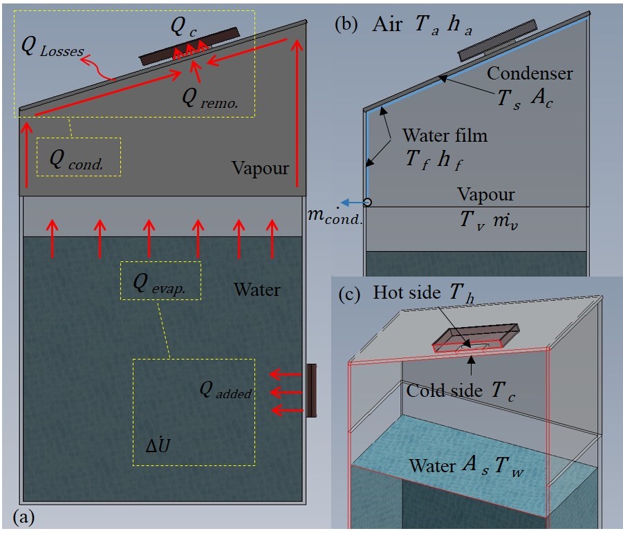 Figure 2. Schematic diagram of: a) The heat balance of the system, b) Evaporation and condensation parameters and c) Hot and cold sides of the thermoelectric module in the system.
Firstly, the conservation of energy at the water-vapour surface for steady state operation is applied. Three heat transfer terms are shown in the system; 1) the heat added Q add to increase or maintain the temperature of the water which is corresponding to the electrical power supply to the heater in the system, 2) The rate of internal energy difference ) of the water, 3) the heat required for the evaporation from the water-vapour surface area which is called in this study the evaporation heat Q evap. Applying the energy conservation to the system, the energy balance takes the form:
![]() At the isothermal process, water temperature remains unchanged. The heat added will be equal to the evaporation heat ( ). In that analysis, the following equation is formed to determine the evaporation heat:
At the isothermal process, water temperature remains unchanged. The heat added will be equal to the evaporation heat ( ). In that analysis, the following equation is formed to determine the evaporation heat:
![]() The rate of produced vapour can be calculated based on the evaporation heat and the latent heat of evaporation at a given water temperature using Steam Tables [29].
The rate of produced vapour can be calculated based on the evaporation heat and the latent heat of evaporation at a given water temperature using Steam Tables [29].
![]() Secondly, the thermal resistance network between the fluids (water film and ambient) and the transmission surface (aluminium condenser) is used to calculate a removed heat .The removed heat is a heat released when the vapour condenses to form a water film. It is a function of overall convective heat transfer coefficient , condenser surface area ( = 0.081 m2) and the temperature difference between the water film (It is a very thin layer of condensed water as shown in Figure 2b) and the condenser surface .
Secondly, the thermal resistance network between the fluids (water film and ambient) and the transmission surface (aluminium condenser) is used to calculate a removed heat .The removed heat is a heat released when the vapour condenses to form a water film. It is a function of overall convective heat transfer coefficient , condenser surface area ( = 0.081 m2) and the temperature difference between the water film (It is a very thin layer of condensed water as shown in Figure 2b) and the condenser surface .
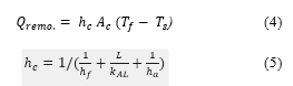 where is the water film heat transfer coefficient which is assumed 100 W/m2 K (the water film at slow velocity and free convection in the system), is the ambient heat transfer coefficient which is assumed 10 W/m2 K and is the thermal conductivity of the aluminium condenser which is assumed 205 W/m. K [30]. The temperature of the water film is calculated as an average between the vapour and the condenser surface temperatures [31].
![]() Thirdly, heat flow through the thermoelectric module is determined by the principles of thermoelectrics under Peltier mode [32]. The absorbed heat at the cold side of the thermoelectric module is:
Thirdly, heat flow through the thermoelectric module is determined by the principles of thermoelectrics under Peltier mode [32]. The absorbed heat at the cold side of the thermoelectric module is:
![]() where α is the Seebeck coefficient of thermoelectric module (assumed to be 0.02 V/K and remains unchanged), I is a DC electric current supply to the thermoelectric module, is the temperature difference between the hot and cold sides of the module (see Figure 2c), K is the thermal conductance of the module (assumed to be 0.1 W/K) and R is the electric resistance of the thermoelectric module (measured value = 0.152 Ω). The first, second and third terms of the right side of Eq. (7) describe the Peltier heat at the cold side of the module, Fourier heat conduction and Joule heating, respectively.
where α is the Seebeck coefficient of thermoelectric module (assumed to be 0.02 V/K and remains unchanged), I is a DC electric current supply to the thermoelectric module, is the temperature difference between the hot and cold sides of the module (see Figure 2c), K is the thermal conductance of the module (assumed to be 0.1 W/K) and R is the electric resistance of the thermoelectric module (measured value = 0.152 Ω). The first, second and third terms of the right side of Eq. (7) describe the Peltier heat at the cold side of the module, Fourier heat conduction and Joule heating, respectively.
The heat balance between the removed heat, the absorbed heat and losses can be expressed as:
![]() where is the condensation heat which is the net amount of heat for water condensation and is the heat losses from the condenser surface to the surrounding. The heat losses is calculated based on the temperature difference between the condenser and the ambient , the convection heat transfer coefficient of the ambient and the area of the condenser surface:
where is the condensation heat which is the net amount of heat for water condensation and is the heat losses from the condenser surface to the surrounding. The heat losses is calculated based on the temperature difference between the condenser and the ambient , the convection heat transfer coefficient of the ambient and the area of the condenser surface:
![]() The rate of the water condensation can then be calculated based on the condensation heat and the latent heat of condensation at the water film temperature using Steam Tables [29].
The rate of the water condensation can then be calculated based on the condensation heat and the latent heat of condensation at the water film temperature using Steam Tables [29].
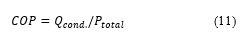
![]() Finally, it is important to calculate the coefficient of performance of the system COP, which is a ratio of the useful cooling provided (condensation heat) to the power required (the total power input to the system ).
Finally, it is important to calculate the coefficient of performance of the system COP, which is a ratio of the useful cooling provided (condensation heat) to the power required (the total power input to the system ).
 4. Experimental Setup
A simplified thermoelectric distillation system was designed and constructed as shown in Figure 3a and b, which consists of an Aluminium condenser chamber, a thermoelectric module, a water heat exchanger, a constant temperature water bath and two variable power supplies.
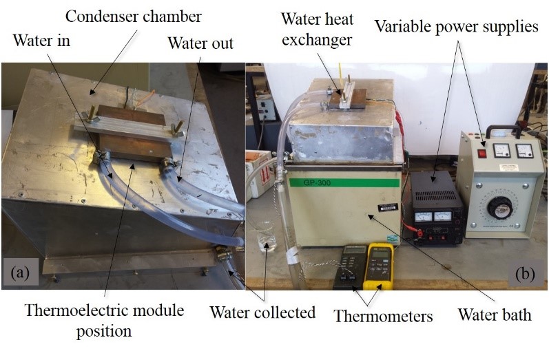 Figure 3. a) Aluminium condenser chamber and b) The experiment setup.
The condenser was fabricated using aluminium sheet (1.5 mm thickness). It was placed on the top of the water bath. One thermoelectric module (4 cm x 4 cm) was used in this study. The water bath and the module were powered by variable power supplies. Cold water was circulated through the water heat exchanger to release the absorbed heat of the module. For effective heat transfer rate, a heat sink compound was used to paste the hot and the cold sides of the module to the water heat exchanger and the condenser, respectively.
Five thermocouples were placed at five different positions in the system to measure the temperatures of the air, vapour, condenser surface and hot and cold sides. The water production was collected and measured every 10 minutes. To examine the experiments more precisely, specifications of the components used in the experiments, together with the module properties and manufacturers information are listed in Table 1. Accuracies, ranges and standard uncertainty of measured instruments are listed in Table 2.
Table 1. Properties of the components used in the experiments.
| Component | Properties | Model / Supplier |
| Thermoelectric Module | Area: 40 x 40 mm2 Thickness: 3.3 mm Current = 8.5 A and Voltage = 15.4 V | CP-14-127-045
Laird Technologies |
| Water Bath | Fluid Temperature = -30 – 150 oC, Tank Size = 24 L, Voltage = 115 V and Current = 11.5 A | GP-300
NESLAB |
Table 2. Accuracies, ranges and standard uncertainty of the measurement instrumentations.
| Instrument | Accuracy | Range | Standard uncertainty |
| Thermocouple (type K) | 0.1 oC | -75 – 250 oC | 0.06 oC |
| Thermometer Fluke 52 | 0.05 oC | -200 – 1372 oC | 0.03 oC |
| Thermometer RS 206 | 0.1 oC | -100 – 1000 oC | 0.05 oC |
| Weir 423 power supply | 0.01 V
0.002 A |
0-15 V
0-2 A |
0.006 V
0.001 A |
| Portable variable transformer CMCTV10 | 0.01 V
0.02 A |
0-300 V
0-10 A |
0.005 V
0.01 A |
5. Results and Analyses
The experiments have been conducted at constant water flow rate through the water heat exchanger. The thermoelectric module was powered at constant voltage of 10 V and current of 2 A. In all experiments, the water production from the system is equalized the water condensation. All experiments were repeated three times for accuracy under steady state operation.
5.1. Water Production at Different Water Temperatures
Figure 4 shows the water production at different water temperatures under one-hour system operation, with and without using thermoelectric module for cooling process (without using TE module means using a cold water in the water heat exchanger for cooling process). The water production was increased when the water temperatures increased from 40 oC to 70 oC. It can be seen also from the Figure that the water production was enhanced twice when using the thermoelectric module for cooling.
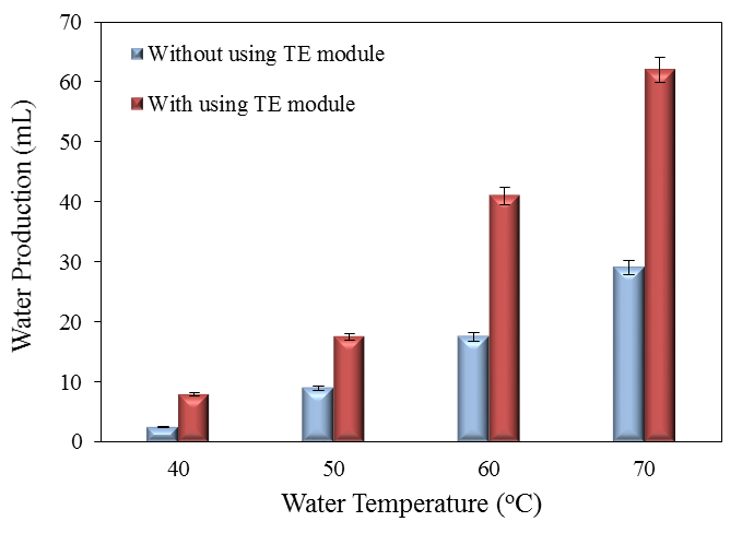 Figure 4. Water production under one-hour system operation at different water temperatures.
5.2. Distillation System at Constant Water Temperature
These experiments have been conducted at constant water temperature 50 oC. This temperature was chosen to study as an average of the maximum range of the water temperatures in solar stills due to the solar irradiation in Middle East in summer (45 oC – 55 oC) [33-36]. For steady state operation, the water bath was powered at constant voltage of 40 V and current of 0.25 A in order to keep water temperature at 50 oC. The thermoelectric module was also powered at constant voltage of 10 V and current of 2 A in order to keep the cold side temperature of the module at 28 oC. Therefore, the evaporation heat, the absorbed heat and the total input power to the system are constant.
5.2.1. Water Production Reliability
Figure 5 shows the water production after three hours of the thermoelectric system operation. It can be seen from the figure that the water production was approximately constant with time which confirms the condensation heat was also constant.
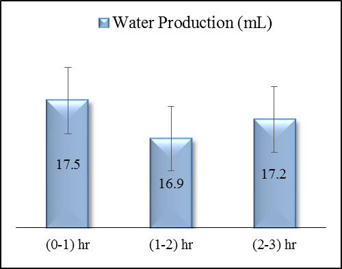 Figure 5. Water production after three hours thermoelectric system operation.
5.2.2. Thermal Behaviour of the System Components
Five different temperatures were measured in the water distillation system during the first hour of thermoelectric operation. The temperatures including; the condenser surface, vapour, ambient, hot and cold sides of the thermoelectric module. It was noticed that all temperatures except the ambient have same behaviour with time as shown in Figure 6.
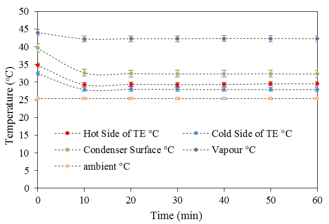 Figure 6. Temperatures variation of the system components.
It was found that the cold side temperature was lower than the condenser surface temperature which indicates that the thermoelectric module was provided cooling to the condenser. The temperature difference between the hot and cold sides of the thermoelectric module was small which means that the thermoelectric module pumped properly the heat from the condenser chamber to the water heat exchanger. At the beginning of the experiments, there was a decrease of the temperatures of the condenser, the hot and cold sides because of the response of the thermoelectric operation. After 10 minutes of the thermoelectric system operation, the temperatures were remained approximately constant.
5.2.3. Validation with the Experimental Data
Figure 7 shows the theoretical and experimental amount of water production during the first hour of thermoelectric system operation. The water condensation rate was calculated theoretically using equation (10) at constant latent heat of condensation (at 37.3 oC water film temperature). The water production rate (condensed and collected in the system) was measured experimentally every 10 minutes. The theoretical model predicts well the rate of water production with reasonable agreement. There is a slight difference between the experimental and calculated theoretical values and this is due to losses during the evaporation and condensation process.
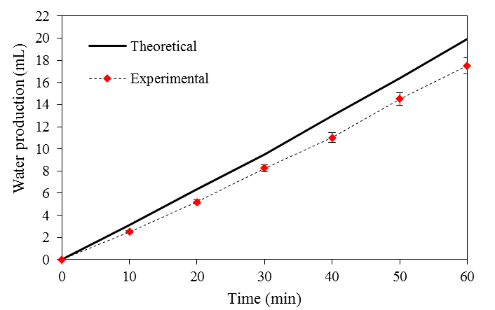 Figure 7. Water production validation with the experimental data.
5.2.4. Percentage of the Beneficial Heat for Water Production
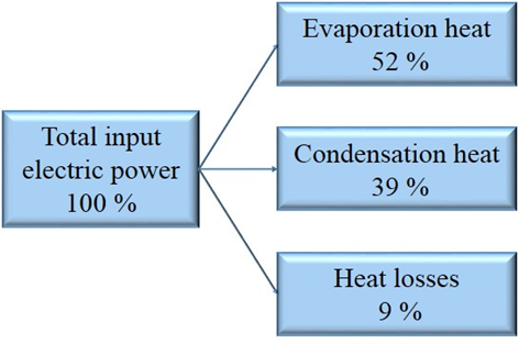 Figure 8. The percentage of the beneficial heat in the system.
Figure 8 shows the heat analysis in the water distillation system under steady state operation. It can be seen that the percentage of the beneficial heat, which is used for the water production, was about 91% based on equation (2) and equation (8), while the percentage of the heat losses to the surroundings was about 9% based on equation (9). The coefficient of performance of the system was 0.3 based on equation (11) under one-hour thermoelectric system operation.
5.2.5. Equilibrium between Evaporation and Condensation Rates
The rate of evaporation is dependent on the surface area of the water-vapour interface and the water temperature. When these factors remain constant, the rate of evaporation will be constant. As well as, the rate of condensation is dependent on the surface area of the condenser and the temperature of condenser (which is entirely dependent on the temperature of the cold side of the thermoelectric module). When these three factors are constant, the rate of condensation will be constant.
Figure 9 shows the evaporation and condensation rates for one-hour system operation at different cold side temperature based on equation (3) and equation (10), respectively. The evaporation rate was maintained steady at constant heat added (10W) and water temperature (50 oC). When the cold side temperature of the module was decreased from 28 oC to 22 oC by increased the current supply to the module from 2 A to 3 A, there was a continual increase in the condensation rate.
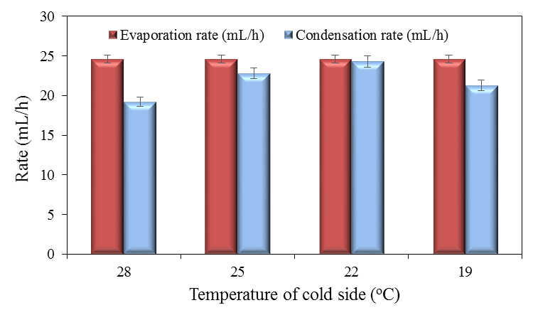 Figure 9. Equilibrium between evaporation and condensation rates.
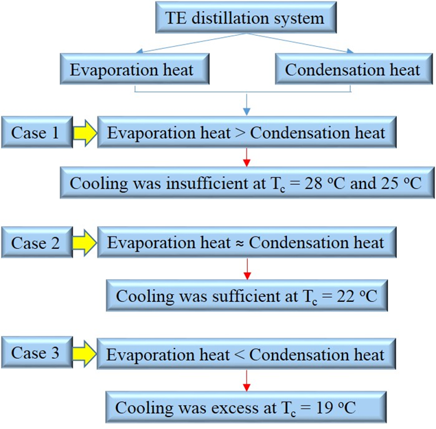 Figure 10. Heat transfer analyses of the system.
The rates of the evaporation and condensation became approximately equilibrium at 22 oC cold side temperature and 50 oC water temperature. When the current supply increased to 3.5 A (19 oC cold side temperature), the condensation rate was decreased with increasing the absorbed heat at the cold side of the thermoelectric module. However, in this case, the cooling was excess.
Based on the results in Figure 9, the heat transfer analyses of the water distillation system is shown in Figure 10. As a conclusion, these results show that the heat involved in the evaporation and condensation processes are an important consideration in the design of an effective distillation system.
6. Conclusions
This study has been investigated to apply the law of conservation of energy to a water distillation system using a thermoelectric module. A theoretical model has been developed to predict the rates of the evaporation and condensation. The theoretical analysis of the heat required for evaporation and condensation processes in the thermoelectric water distillation system was carried out to assist in design of high performance thermal distillation system. This analysis is an effective tool for energy saving issues. A prototype distillation system integrated with one thermoelectric module was designed and fabricated to measure the rates of the evaporation and condensation under one-hour steady state. The results show that there is a reasonable agreement between the theoretical model and the experimental data, the percentage of the beneficial heat for the water production was about 91% and the rates of the evaporation and condensation became approximately equilibrium at 22 oC cold side temperature and 50 oC water temperature.
- Loucks, D.P., 2017. Managing water as a critical component of a changing world. Water Resources Management, pp.1-12.
- Petersen, L., Heynen, M. and Pellicciotti, F., 2017. Freshwater Resources: Past, Present, Future. The International Encyclopedia of Geography.
- Manju, S. and Sagar, N., 2017. Renewable energy integrated desalination: A sustainable solution to overcome future fresh-water scarcity in India. Renewable and Sustainable Energy Reviews, 73, pp.594-609.
- Sommariva, C., 2017. State of the Art and Future Applications of Desalination Technologies in the Middle East. In Water, Energy & Food Sustainability in the Middle East (pp. 107-124). Springer International Publishing.
- Chandrashekara, M. and Yadav, A., 2017. Water desalination system using solar heat: A review. Renewable and Sustainable Energy Reviews, 67, pp.1308-1330.
- Ghaffour, N., Bundschuh, J., Mahmoudi, H. and Goosen, M.F., 2015. Renewable energy-driven desalination technologies: A comprehensive review on challenges and potential applications of integrated systems. Desalination, 356, pp.94-114.
- Sharon, H. and Reddy, K.S., 2015. A review of solar energy driven desalination technologies. Renewable and Sustainable Energy Reviews, 41, pp.1080-1118.
- Likhachev, D.S. and Li, F.C., 2013. Large-scale water desalination methods: a review and new perspectives. Desalination and Water Treatment, 51(13-15), pp.2836-2849.
- Drioli, E., Ali, A. and Macedonio, F., 2015. Membrane distillation: Recent developments and perspectives. Desalination, 356, pp.56-84.
- Shahzad, M.W., Burhan, M. and Ng, K.C., 2017. Pushing desalination recovery to the maximum limit: Membrane and thermal processes integration. Desalination, 416, pp.54-64.
- Al-Sulttani, A.O., Ahsan, A., Rahman, A., Daud, N.N. and Idrus, S., 2017. Heat transfer coefficients and yield analysis of a double-slope solar still hybrid with rubber scrapers: An experimental and theoretical study. Desalination, 407, pp.61-74.
- Eldeeb, R., Aute, V. and Radermacher, R., 2016. A survey of correlations for heat transfer and pressure drop for evaporation and condensation in plate heat exchangers. International Journal of Refrigeration, 65, pp.12-26.
- Sathyamurthy, R., El-Agouz, S.A. and Dharmaraj, V., 2015. Experimental analysis of a portable solar still with evaporation and condensation chambers. Desalination, 367, pp.180-185.
- [14] H. Al-Madhhachi, M. Phillips and G. Min, “Validation of Vapour/Water Production in a Thermoelectric Distillation System” in Proceedings of the 3rd World Congress on Mechanical, Chemical, and Material Engineering (MCM’17), Roma, Italy, 2017. ISSN: 2369-8136. DOI: 10.11159/htff17.117.
- Mishra, D.R., Tiwari, A.K. and Sodha, M.S., 2016. Mathematical modeling and evaluation of new long single slope still for utilization of hot wastewater. Applied Thermal Engineering, 108, pp.353-357.
- Elsheikh, M.H., Shnawah, D.A., Sabri, M.F.M., Said, S.B.M., Hassan, M.H., Bashir, M.B.A. and Mohamad, M., 2014. A review on thermoelectric renewable energy: Principle parameters that affect their performance. Renewable and Sustainable Energy Reviews, 30, pp.337-355.
- Chein, R. and Huang, G., 2004. Thermoelectric cooler application in electronic cooling. Applied Thermal Engineering, 24(14), pp.2207-2217.
- Bell, L.E., 2008. Cooling, heating, generating power, and recovering waste heat with thermoelectric systems. Science, 321(5895), pp.1457-1461.
- Goldsmid, H.J., 2016. Theory of Thermoelectric Refrigeration and Generation. In Introduction to Thermoelectricity (pp. 9-24). Springer Berlin Heidelberg.
- Riffat, S.B. and Ma, X., 2003. Thermoelectrics: a review of present and potential applications. Applied thermal engineering, 23(8), pp.913-935.
- Al-Madhhachi, H. and Min, G., 2017. Effective use of thermal energy at both hot and cold side of thermoelectric module for developing efficient thermoelectric water distillation system. Energy Conversion and Management, 133, pp.14-19.
- Moh’d A, A.N. and Al-Ammari, W.A., 2017. Utilizing the evaporative cooling to enhance the performance of a solar TEG system and to produce distilled water. Solar Energy, 146, pp.209-220.
- Demir, M.E. and Dincer, I., 2017. Development of an integrated hybrid solar thermal power system with thermoelectric generator for desalination and power production. Desalination, 404, pp.59-71.
- Rahbar, N., Esfahani, J.A. and Asadi, A., 2016. An experimental investigation on productivity and performance of a new improved design portable asymmetrical solar still utilizing thermoelectric modules. Energy Conversion and Management, 118, pp.55-62.
- S. S. Al-Madhhachi, “Solar Powered Thermoelectric Distillation System,” Ph.D Thesis, Cardiff University, 2017.
- Date, A., Gauci, L., Chan, R. and Date, A., 2015. Performance review of a novel combined thermoelectric power generation and water desalination system. Renewable energy, 83, pp.256-269.
- Aberuee, M.J., Baniasadi, E. and Ziaei-Rad, M., 2017. Performance analysis of an integrated solar based thermo-electric and desalination system. Applied Thermal Engineering, 110, pp.399-411.
- Al-Madhhachi, M. Prest and G. Min, G., “ Evaluation of the convection heat transfer coefficient in a thermoelectric distillation system” in 2016 International Conference for Students on Applied Engineering (ICSAE), Newcastle UK, 2016, (pp. 213-217). IEEE. DOI: 10.1109/ICSAE.2016.7810190.
- Keenan, J.H. and Keenan, J.H., 1992. Steam tables: thermodynamic properties of water, including vapor, liquid, and solid phases (English units). United States of America: Second edition. John Wiley & Sons.
- Bejan, A., 2013. Convection heat transfer. John wiley & sons.
- Bergman, T.L. and Incropera, F.P., 2011. Fundamentals of heat and mass transfer. John Wiley & Sons.
- Rowe, D.M. ed., 1995. CRC handbook of thermoelectrics. CRC press.
- Phadatare, M.K. and Verma, S.K., 2007. Influence of water depth on internal heat and mass transfer in a plastic solar still. Desalination, 217(1-3), pp.267-275.
- El-Sebaii, A.A., Al-Ghamdi, A.A., Al-Hazmi, F.S. and Faidah, A.S., 2009. Thermal performance of a single basin solar still with PCM as a storage medium. Applied Energy, 86(7), pp.1187-1195.
- Rahbar, N. and Esfahani, J.A., 2012. Experimental study of a novel portable solar still by utilizing the heatpipe and thermoelectric module. Desalination, 284, pp.55-61.
- Baalbaki, A., Ayoub, G.M., Al-Hindi, M. and Ghauch, A., 2017. The fate of selected pharmaceuticals in solar stills: Transfer, thermal degradation or photolysis. Science of The Total Environment, 574, pp.583-593.