Linear algebra as an alternative approach to the synthesis of digital devices of automation and control systems

Adv. Sci. Technol. Eng. Syst. J. 3(1), 168–190 (2018);
 DOI: 10.25046/aj030121
The article considers linear algebra as an alternative mathematical tool of logic synthesis of digital structures to Boolean algebra and synthesis methods of digital electronic component base (ECB) on its ground. The methods of solving the applied problems of logic synthesis are shown, including the expansion of an arbitrary logic function by means of monotonic functions. The proposed mathematical apparatus actually provides the creation of digital structures on the principles of analog circuitry. It can find application in the design of multivalued digital ECB, specialized system-on-chip and analog-digital sensors with current output. The examples of synthesis of the combinational and sequential two-valued and multivalued digital devices are given. In conclusion, the advantages of linear algebra in comparison with Boolean algebra are formulated.
1. Introduction
This article is a continuation of the studies presented at the conference SIBCON-2017 [1].
Boolean algebra is known [2] as a leading mathematical tool for logic synthesis of two-valued digital structures. Almost all existing methods of logic synthesis are formed on its ground. The success of Boolean algebra is caused, among other things, by the fact that the Boolean representation of the realized logic function turned out to be rather technological: the circuit implementation of logic elements was relatively simple. TTL, C-MOS and ESL and other technologies occurred to be the most preferable for this purpose.
Despite this, the history of the development of digital microelectronics knows the attempts to replace both the approach to logic synthesis (the use of spectral representations [3 – 6] using the arithmetic polynomials [7 – 9]) and technological realization (I2L, I3L, …).
The most significant contribution to the alternative theory of logic synthesis has been made by the threshold interpretation of Boolean algebra, called the threshold logic.
Threshold logic related to one of the directions of synthesis of the digital structures [10], is constantly evolving. We know a significant number of publications devoted to this problem [11 – 14]. For two-valued functions, the threshold synthesis problems have already been solved beginning from the well-known papers of М. Dertouzos [10]. One of the advanced approaches of synthesis for the k-valued threshold functions is considered in this article [11].
The threshold logic was initially implemented in a two-valued version, but many publications on the multivalued threshold logic have recently appeared [14 – 17]. Why are they dedicated to the multivalued logic? The fact is that the multivalued logic is currently considered as a means of improving the quality characteristics of LSI (the ratio of “number of elements / number of links”, “total area / real-estate” of the crystal, etc.), which doesn’t require a drastic change in LSI technology. The authors of this article also follow this approach.
To develop this ideology we proposed an alternative approach to the logic synthesis of digital devices – the replacement of the mathematical tool of Boolean algebra by another body of mathematics – linear algebra. Such a replacement entailed fundamental changes in various aspects of the implementation of digital structures:
– the potential realization of Boolean logic was replaced by the current linear implementation;
– the key operating mode of the elements was replaced by the linear one;
– Boolean values of the variables took a quantitative form instead of the qualitative (logic) one;
– the value of logic was determined not by the scheme, but by the significance of signals;
– the output signal was presented by the difference of signals of two circuits operating in parallel, which improves the performance of digital structures.
Thus, the use of linear algebra as a mathematical tool of the logic synthesis ensured the development of alternative methods for the logic synthesis of current digital circuits and their practical implementations.
The authors published a number of papers [18-32] devoted to the synthesis of logic (nonthreshold) two-valued and multivalued digital structures. This paper considers the use of linear algebra as a mathematical tool for the logic synthesis of two-valued and multivalued, logic and threshold digital structures.
The fuzzy concept of the “threshold synthesis” can be interpreted in two ways:
– as a normal logic synthesis of digital structures with circuit implementation on threshold logic elements (any logic function can be implemented in this way);
– as a logic synthesis of threshold logic functions (an arbitrary logic function can be implemented by a network of threshold logic elements).
The purpose of this article is to propose logical and threshold current hardware components for constructing digital structures within the two specified areas. Within the framework of this goal, the authors’ solutions for the following tasks are given below:
– since linear algebra is used as a mathematical tool for the logic synthesis of current logic structures, the article presents the main definitions and aspects of the practical use of linear algebra;
– as there is a close relationship between the threshold and monotonic functions, the article gives a definition of the monotonic function and explains the ways of representing arbitrary functions by monotonic linear functions;
– some versions of transformation of two-valued and multivalued monotonic functions into a threshold form in linear algebra are analyzed;
– versions of circuit implementation of linear threshold logic elements are considered.
2. Linear Algebra
А. Definition of linear algebra. Let Р ® áР; +, ∙, 0.1ñ – field, áА; +, ∙, θñ – algebra with two binary operations and one nullary operation. The system Λ ® áА; +, ∙, θ, Рñ is called linear algebra, if the following conditions are met:
– the system Λ ® áА; +, ∙, θ, Рñ – linear (vector) space over the field Р;
– distributivities of operations + and ∙![]()
– associativities of vector multiplication by elements of the field Р
“(a, b Î A)Ù”(k Î P) k(ab) = (ka)b = a(kb).
В. Extension of linear algebra.
Let А ® áА; +, ∙, θñ – vector space of linear algebra Λ, Р ® áР; Ω = {wk|kÎP}, 0.1ñ – field of linear algebra Λ, which contains the operations wk, which in general case do not necessarily coincide with the operations of linear space А. Then the system Λ’ ® á{А; +, ∙, θ}, {Р; Ω, 0, 1}ñ is called the extension of linear algebra Λ.
When interpreting this algebraic system in a certain way, we can obtain algebras with different properties. For example, interpreting A as a set of terms of Boolean functions f(x1,…, xn), the operations “+” and “·” – as max(x1,…, xn), min(x1,…, xn), we obtain algebra А ®áА; max, min, θ; Pñ. Similarly, leaving the semantics of operations in the original form (i.e., defining them as ordinary arithmetic operations), we can consider the reduced system as linear algebra on the set A of vectors in a linear space. The reduced algebraic system is considered below in this form.
- Creation of bases. To form the bases from logic variables, it is possible to construct different constructions of linearly independent vectors with given properties. The choice of operations for creation of the bases is made independently on the operations of linear space and can be determined by various (mathematical, circuit, technological and other) requirements. In the applied plan, this allows obtaining the ideologically unified (based on operations of linear space) circuit solutions of functional elements (from different implementations based on field operations).
A basis is a system of m linearly independent vectors {F} = {j0, j1,…, jm-1}, which enables to describe any vector a Î A in the linear form![]()
with respect to these vectors.
Each vector of the basis {F} = {j0, j1,…, jm–1} is uniquely determined by the set of coordinates ji = {ji0 , ji1,…, ji,m–1}, with the help of which we can make a square matrix of order m: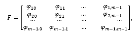
corresponding to the given basis {F}.
Two bases and , the matrices F and Y of which are inverse to each other, are reciprocal (dual). Besides,
F Ч Y = E,
where E – diagonal matrix of order m with eij = 1, when i = j and eij = 0, if i ¹ j, which is an orthonormal basis {E}.
Since the resolution of an arbitrary vector a over the basis {F} has the form
a = a0j0 + a1 j1 + ЧЧЧ +am-1 jm-1,
then, multiplying both parts of this resolution by gi, i = [0, m-1], we obtain:![]()
Then the procedure for representing (i.e. obtaining the values of the expansion coefficients) of the arbitrary vector a in the given basis {F} is reduced to performing the following operations:
– construction of the basic matrix F;
– construction of the inverse basic matrix F-1;
– multiplication of the row-vector a by the column-vector of the matrix F-1 and computation of the expansion coefficients of the vector a over the basis {F};
– writing of the expression for the vector a in the linear form (1) with respect to the basis {F}.
Example 1. Get a representation of the conjunction operation of two arguments of the value 2 in the basis
а) we represent the sequence of values of the two-valued logic function by the row-vector
b) we multiply the resulting row-vector by the columns of the inverse basic matrix and obtain the row-vectors of the expansion coefficients of the represented logic function with respect to the given basis and the expression of the conjunction operation
It is noteworthy that the last expression has been known since 1953 [3], but the author didn’t describe the method of its obtaining (more precisely, it was described later).
The authors of this article propose three approaches to the creation of the basis vectors of linear bases, depending on the operations used for this purpose:
– based on Boolean operations , &, , , etc .;
– based on the truncated difference operation ;
– based on the comparison operation ≥.
When using Boolean operations, the upper and lower “cuts” [14, 18] of variables of different orders are used as operands for creating basis vectors:
– variables of the first order , ;
– variables of the second order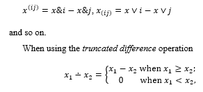
all logical operations are replaced by some combinations of this operation on variables involving operations of linear space. For example, the upper and lower “cuts” of the first and second orders are replaced by the expressions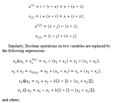
When using the comparison operation, the above expressions are reduced to the following form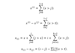
It should be noted that the most interesting result of the studies is the fact of constructing logical structures based on truncated difference and comparison operations other than Boolean ones. Naturally, there are certain dependencies between the truncated difference and comparison operations, some of which are given below:
-“truncated difference – comparison”: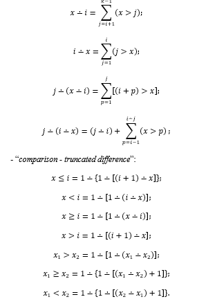
3. Monotonic Logic Functions
Regarding the close connection between threshold and monotonic functions, we present some known results obtained in linear algebra in a simpler and more obvious way.
А. Construction of sequences of nondecreasing componentes. Suppose we have an arbitrary vector . We renumber the components of the vector with k-ary n-bit numbers. The vector aÎ Zm is called monotonically increasing (decreasing), if for a bitwise comparison of k-ary number codes of the components ai and aj we have:![]()
The bitwise comparison of k-ary number codes of the components enables to single out the sequences of nondecreasing (nonincreasing) components.
The necessity to create these sequences is that for the monotonicity of the vector, condition (2) must be met in each sequence. Hence follows the first factor of simplicity of the analysis results in linear algebra: to verify the vector by monotonicity it is sufficient to establish its monotonicity within each sequence. This reduces the amount of computation and the overall complexity of the verification process.
The sequences of nondecreasing components are constructed as follows. The set G of components (constituents 1) of logic functions of the chosen number of n variables is divided into n groups . Each group includes the sequences of nondecreasing components with starting numbers t, , determined by the following relation in this case we take . The starting numbers are component numbers that should be compared with the values of the other elements in the sequence. Each sequence contains components with numbers the decimal equivalents of which are determined as . As a result, the entire sequence generally takes on the form
Thus, it is possible to construct the sequences of nondecreasing components for the given values of k and n. The sequence graphs of nondecreasing components for k = 2, k = 3 and n = 3 are shown in Figure 1. The digits in the circles denote the decimal numbers of the vector components, and the sequence itself includes a certain vertex and the nearest right vertexes connected with it by the lines.
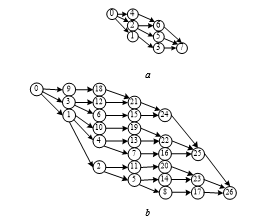 Figure 1: Sequence graphs of the nondecreasing components
for k = 2, k = 3 and n = 3.
Example 2. Construct sequences of nondecreasing components for k = n = 3. Since n = 3, there are 3 groups of sequences with starting numbers 0, 1 and 2 for the initial data under consideration.
For group “0”, the value of t0 varies in the range
,
or .
Therefore, this group includes two sequences with the initial elements t00 = 0 and t01 = 1. The first sequence g00 of the group “0” contains the elements with numbers t00, t00 + 30 , t00 + 31, t00 + 32 , i.e. 0, 1, 3, 9. The second sequence g01 of the group “0” comprises the elements with numbers t01 , t01 + 30 , t01 + 31, t01 + 32 , i.e. the elements with numbers 1, 2, 4, 10.
Similarly, for group 1, the value of t1 is
,
or
.
Consequently, this group includes sequences with the initial elements g1t = 2… 5, and each sequence of the group comprises the elements with numbers t1j, t1j + 31, t1j + 32.
Finally, for group 2, the value of t2 is
,
or
,
i.e. this group contains sequences with the initial elements g2t = 6 … 17, and each sequence includes the elements with numbers t2j, t2j + 32. Thus, we obtain the sequence structure of nondecreasing components in the form shown in Figure. 1b.
The monotonicity property of vectors from Zm enables to obtain various representations of an arbitrary vector by means of monotonic vectors. Let’s consider such representations in the following three variants:
– the difference of two monotonic vectors that have a value greater than the significance of the represented vector;
– the algebraic sum of monotonic vectors of the same value as the original vector;
– the algebraic sum of monotonic vectors of the value, the smaller value of the represented vector.
В. The problem of representing the logic function by the difference of two monotonic vectors of greater significance is solved by the following algorithm [18]:
Algorithm 1.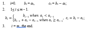
- i = m, the end.
Here i and i–1 are neighboring indices of the elements in the sequence of nondecreasing components, . The validity of the algorithm results from the following elementary arguments.
- Let b0 = a0 , then c0 = b0 – a0 = 0.
- Let the pair of components add and agg satisfies the condition of monotonicity, i.e. . In this case
,
and, consequently, from the identity
it follows that
,
i.e. also meets the monotonicity condition.
- If the pair of components ag and ad doesn’t fulfill the condition of monotonicity, i.e. g , then, taking we remain the monotonicity condition for the components of the vector b again.
Example 3. Construct a representation of the vector a = {0, 1, 1, 0, 1, 0, 0, 1, 1, 0, 1, 1, 1, 1, 1, 0} as a difference of two monotonic vectors for k = 2, n = 4, m = kn = 16.
The sequence of nondecreasing components for this case has the following form:
Table 1
| g | Sequences | Values of components |
| 0 | 0, 1, 2, 4, 8 | 0, 1, 1, 1, 1 |
| 1 | 1, 3, 5, 9, | 1, 0, 0, 0 |
| 2 | 2, 6, 10 | 1, 0, 1 |
| 3, 7, 11 | 0, 1, 1 | |
| 3 | 4, 12 | 1, 1 |
| 5, 13 | 0, 1 | |
| 6, 14 | 0, 1 | |
| 7, 15 | 1, 0 |
We construct the components of the vectors b and c: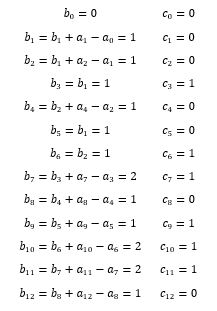
The described algorithm demonstrates one more fact, which confirms the simplicity of analysis in linear algebra.
As it can be seen from the example, when using the described algorithm in the general case, the value of the original vector does not coincide with the significance of the resolution vectors.
- The expansion of the arbitrary logic function of n arguments into the algebraic sum of monotonic logic functions of the same value of the following form
where p £ kn, – monotonic expansion functions with the property j1 É j2 É…, are made in accordance with the following algorithm [18].
Algorithm 2.
- We choose a minimal summation of the positive summands of the arithmetic-logical representation of the logic function covering (in the logical sense) all other positive summands, and combine it by the operation Ú. Thus, we form the first expansion function . To remain the equality, all possible logical products of summands from with the signs defined as (–1)j, where 1 < j < s, s is a number of summands in , . Then we reduce similar terms and represent the initial logic function in the following form , where is a remainder of the initial function after reduction of similar terms.
- We repeat clause 1 for . As a result, the initial logic function is represented in the following form
We repeat clause 2 until the remainder of the initial logic function becomes zero.
Since the number of arguments of the logic function is n, and the violation of monotonicity is possible in each of the k values of each argument, then, the maximum number of the expansion functions doesn’t exceed 2n(k–1).
The process convergence follows from the fact that each successive resolution vector eliminates some violation of monotonicity in the original vector and doesn’t introduce new monotonicity violations, since it is monotonic itself.
The problem of representing the arbitrary logic function by the algebraic sum of monotonic functions of the same value can be solved analytically. As is known [13], the minimal disjunctive normal form (DNF) of the monotonic logic function doesn’t contain inversions over variables. Consequently, the given logic function must be reduced to the representation in the form of the algebraic sum of such functions. To do this, we must perform the following actions:
– conversion of the Boolean expression of the logic function into the linear one using the following identities
– inverse transformation to the given (that doesn’t contain inversions over variables) form.
Example 4. Obtain the two-valued logic function mapping of three arguments
into the algebraic sum of monotonic logic functions.
Solution. The logic function is represented by a vector of values. Its linear representation has the following form
Now we obtain the mapping of this function into the algebraic sum of monotonic functions. The first expansion function is formed from the first three summands, covering in aggregate all the remaining positive terms of sum:
The subsequent expansion functions are obtained in the same way:
To obtain the threshold representation of the initial function, it suffices to transform the monotonic functions of the resulting expansion into the threshold form and to perform their algebraic addition.
Each conjunctive term of any logical expansion function is transformed into the threshold form in accordance with the following identical equation
where t – a number of arguments in the term, P – the predicate symbol. Then all the terms are reduced to the common value of the right-hand side with the introduction of the corresponding coefficients for the variables, then they are added together and the threshold value of the received sum is determined.
Let’s explain the transformation of the monotonic logic function into the threshold form with the function from the previous example.
With the transformation of everything is simple: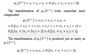
Thus, to realize the considered logic function, three threshold logic elements are required. The simplicity of the transformations in linear algebra becomes obvious.
- Representation of the arbitrary vector by the vectors of lower significance. This problem has many solutions. The variant considered below assumes the solution of this problem in two stages:
– obtaining a representation of the arbitrary vector from Zm by the vectors of lower significance;
– transformation of the obtained representation into the representation by means of monotonic vectors.
Let us first consider the solution of the first stage of the problem. The representation of the arbitrary vector by the lower-valued vectors can be obtained by weighting (each resolution vector is included into the final representation with some weight coefficient) or unitary (each resolution vector is included into the final representation with a unitary weight coefficient) coding.
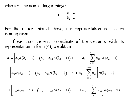
- It is known from the theory of numbers [33] that any number a can be uniquely represented in the following form:
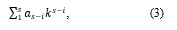
where s = [logk a] – the closest integer to logk a, as-i – the values of the expansion coefficients of the number a in the k-valued number system. Due to the uniqueness, this relation determines the isomorphism between any number a and the described representation of this number.
thus, it is applicable to the vectors of the linear space. If now we associate the vector a to the number a in the linear space Zm, and the weighted sums of the vectors as–i of the spaces and to the weighted sums and correspondingly, then the expression (3) is equivalent to the representation of the vector а Î Zm by the weighted sum of the vectors from or respectively. Since in both spaces the vector a is uniquely represented, both representations are isomorphic. Let’s call such a representation by coding, and the corresponding linear operator – by the encoding operator.
Let the vector а Î Zm in the canonical basis be represented as
Using expression (3), we expand each coordinate of the vector a with respect to the bases k1 and k2. As a result, we obtain its representation in the following form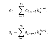
where ai,s-i – the expansion components of the number ai (i – е vector components ai of the vector representation a).
Then the vector representation a in each of the spaces can be described in the following form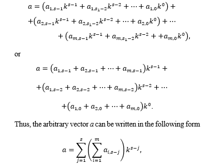
i.e. а is represented by the weighted sum s of the vectors from or
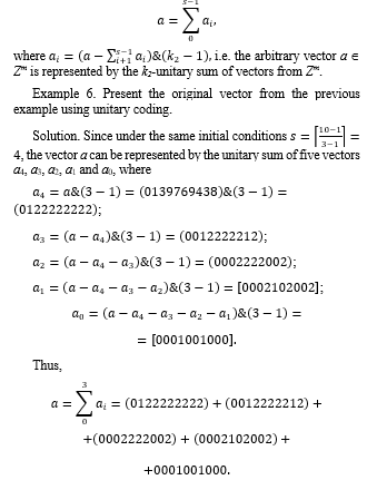
Example 5. Let k1 = 10, n = 1. The problem is to represent the vector a = {0, 1, 3, 9, 7, 6, 9, 4, 3, 8} by its k2-weighted and k2-unitary sums of the vectors when k2 = 3.
Solution. Since , then the vector a can be represented by the weighted sum of three vectors а2, а1 and а0. The coordinates of the highest weight vector а2 are determined as 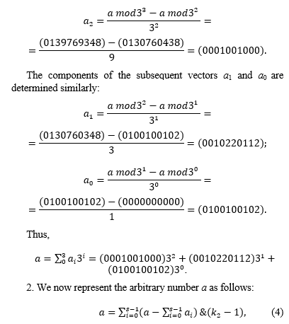
The solution of the second stage of the problem, i.e. the transformation of the obtained representation into the representation by means of monotonic lower-valued vectors, can be obtained on the base of algorithm 2.
Thus, the body of the linear space theory determines easy-to-use means of representing arbitrary vectors of any given value by monotonic vectors of greater, similar or lesser significance, and also converting monotonic functions to the threshold form.
4. Synthesis of Logic and Threshold Elements
In linear algebra, the logic function is represented by a weighted algebraic sum of terms. As a whole the variables, terms and function take values from the set of numbers 0, 1, …, k – 1. The algebraic sum is realized by operations of the linear space, and individual terms – depending on the choice made – by other operations chosen for technical, technological or operational reasons. In this article, “Truncated Difference” and “Comparison” are used as such operations. In the future, the developers of linear LSIs can be motivated to choose other operations. Thus, the process and the possibilities of logic synthesis will be further demonstrated on the bases based on the truncated difference and comparison operations.
To solve the problems of logic synthesis in linear algebra, first, it is necessary to solve the problem of the formation of bases.
In Boolean algebra, 17 previously defined functionally complete systems of logic functions of two arguments are known [34]. Selecting any of them, you can get its linear analog and perform a logic synthesis of the circuit that implements the given logic function according to the established algorithm. Therefore, it is possible to construct bases as a mapping of Boolean functionally complete systems to a linear space. For truncated difference and comparison operations, the bases can be formed directly.
To form the bases, we need:
– a set of operations;
– a set of generating functions.
The following operation are considered as the basic ones:
– logical operations in their traditional understanding;
– operation “truncated difference”;
– operation “comparison”.
Constants 1, logical variables , , …, and their totals subjected to the effect of basic operations are used as generators for the formation of bases.
The following methods of logic synthesis of digital structures are considered:
– direct synthesis in a given basis (logic synthesis in the linear space);
– synthesis with preliminary transformation of the value of the given function (for example, a multivalued two-digit implementation);
– synthesis with preliminary expansion of the given function into the algebraic sum of monotonic functions (threshold synthesis).
The first method is the most obvious and consists in the representation of the realized logic function in the chosen basis.
The second method presupposes a preliminary representation of the realized function in the form of an algebraic sum of logic functions larger, smaller or equal to the original value. The methods of this transformation have been described in the previous section.
Finally, the third method consists of the preliminary representation of the realized function by the algebraic sum of monotonic logic functions. In this case, each monotonic function is realized by a single threshold element.
Note that the synthesis of digital structures with increasing of their complexity, as usual, requires the involvement of methods of system engineering.
- Basic operations of logic synthesis. The set of operations most often used to represent logic functions will be considered as basic operations of logic synthesis. In Boolean algebra, such operations can be considered as operations of the basic functional system AND (&), OR (˅), ( ̅ ), and also the operations “modulo 2 sum” (Å), “logic equivalence” (~) “dual stroke” (↓), “Sheffer stroke” (|), “prohibition with respect to х1 (х2)” , “implication from х1 to х2)” ( ), majority operation .
By basic operations of linear algebra we mean arithmetic operations (operations of the linear space), as well as operations used to form bases. We classify the current realizations of logical operations: the difference module, the truncated difference, the arithmetic sum and the difference, the multiplication by a constant coefficient, the operations of changing the sign to them. Perhaps there are other arithmetic operations suitable for the use in linear logic synthesis, but they are not considered in this article.
Since our task is logic synthesis in linear algebra, we start with the logic synthesis of basic operations of linear algebra.
Algebraic sum. The operation is realized by the assembly connection of conductors, over which the currents flow. The conditional graphic representation of the operation of the algebraic sum is shown in Figure 2.
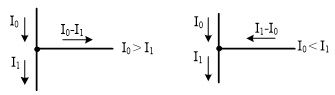 Figure 2: Conditional graphical representation of the algebraic addition of currents.
The arithmetic sum differs from the algebraic one in that in the latter case the signals of only one sign (i.e. only inflowing or only flowing out) are fed to the input of the element. From the output, the sum of the signals is removed. The positive direction of the input currents is the current direction to the connection point S1, i.e. the positive current flowing into the connection point. The negative direction of the input currents is the direction of the current from the connection point of the conductors S1, i.e. negative – the current flowing from the connection point. For the output (resulting) current, the positive direction is the direction from the connection point S1, and the negative direction – to the connection point S1,
The number of positive and negative inputs is determined by the function being implemented. Since the logical variables take values from the positive semi-axis of the numerical axis, when subtracting, it is necessary to meet the condition that the total sum of the negative summands (current quanta) doesn’t exceed the total sum of the positive terms of the sum. Otherwise, instead of the algebraic sum, the truncated difference operation is performed, in which the subtraction from zero is a logical component of this operation and which carries the meaning of the comparison operation with zero (Figure 3)
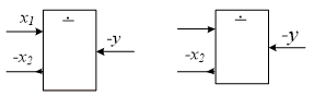 Figure 3: Conditional graphic representation of the truncated difference operation.
The operation of multiplying (dividing) by a constant coefficient consists in multiplying the input signal by several outputs and then combining the outputs of the multiplied signal (when multiplying) or outputting some part of the input signal (when dividing), as shown in Figure 4.
The comparison operation is used to determine the relationship between the compared variables. It can be performed in two forms: in the relative form, i.e. in the form of determining the difference in the values of the variables, or in the absolute form, i.e. in the form of the “more-less” comparison itself. The conditional graphic symbols of the comparison elements in these forms are shown in Figure 5.
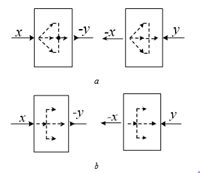 Figure 4: Conditional graphic representation of the operation of multiplication (a) and division (b).
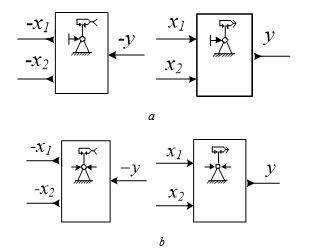 Figure 5: Conditional graphic representation of the comparison operation: relative (a) and absolute (b).
The operation of changing the sign of terms allows changing the sign of the term, thereby transforming it from the summand to the subtrahend and vice versa. It is performed by the current inverter, the conditional graphic representation of which is shown in Figure 6.
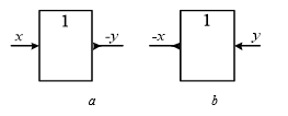 Figure 6: Conditional graphic representation of the operation of changing the sign.
The operation of changing the sign can functionally be combined with the operations of multiplication and division by the constant coefficient.
- Formation of bases. The bases being formed are bases of the linear space, and according to the form they are sets of variables and their various combinations (terms) combined by the selected operations. We can approach to the formation of bases from different sides. For the two-valued synthesis, as it was shown above, it is possible, for example, to construct bases equivalent to 17 functionally complete systems (logical-arithmetic), and then create their analogs in linear algebra.
To form the multivalued bases, we can use the cuts of multivalued variables (10 combinations of such cuts are proposed in [18]), and then construct their analogs in linear algebra. Such a solution is also applicable for the two-valued bases. The problem of forming the bases is solved uniformly for the cuts of any type, so we demonstrate its solution on the basis of the upper cuts of the first level, which are analogs of the functionally complete system AND, NOT (OR, NOT).
The bases of this type for k = 2, n = 2 and n = 3, and for k = 3, n = 2 are given below. For each basis, the basic and inverse matrices are presented. Two-digit operations & and ∨ and their multivalued analogs and are used as generating operations. Therefore, the bases of this type are called logical-arithmetic.
The two-valued logical-arithmetic bases of two variables have the form:
– conjunctive (AND, NOT)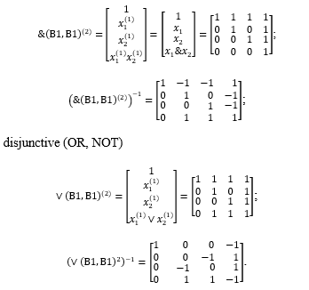
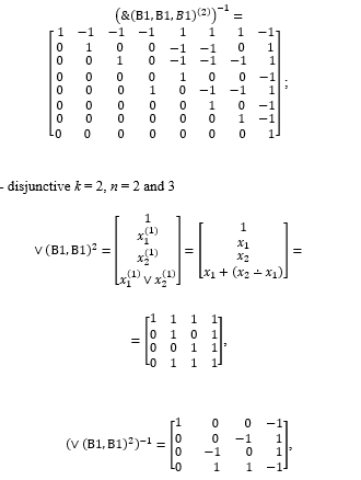
The two-valued logical-arithmetic bases of three variables have the similar form: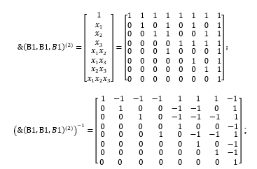
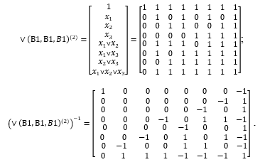
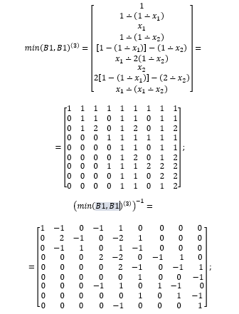
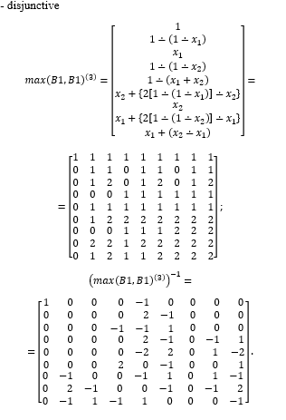
The three-valued logical-arithmetic analogs of these bases look like this:
– conjunctive 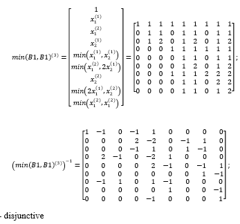
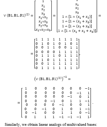
To obtain linear analogs of the above logical-arithmetic bases, we can use the relations that establish the connection between logical operations, on the one hand, and with the operations used to form the bases of linear space, on the other hand. For the bases of the considered type these relations are as follows:
– logical operations – truncated difference operation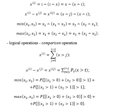
Using the above relations, we can easily obtain linear analogs of the above bases:
– conjunctive k = 2, n = 2 and n = 3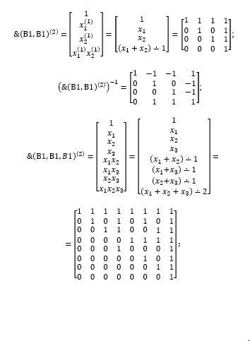
- Logic synthesis of basic functions. The resulted conditional graphic designations of operations of the linear space can be used for graphic representation of basic Boolean logic operations in linear algebra and construct functional schemes of logic elements on their base. For this it is sufficient:
– to choose the basis from the listed above;
– to use the previously described technique of logic synthesis in linear algebra.
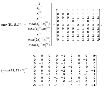
We choose a conjunctive version of the chosen basis as an object of logic synthesis in which we perform a logic synthesis of the two-valued and three-valued functions of circular shift
In accordance with the above, the first action is to obtain the expansion vector of the value vector of the function in terms of the basis. Multiplying the vectors written above by the columns of the inverse matrix of the bases and results in the following:
 Weighing the basis vectors with respect to the obtained coefficients, we obtain expressions of the logic functions in the given basis
 The functional schemes corresponding to these expressions are shown in Figure 7 a, b, c.
To obtain the equivalent expressions of the functions in linear analogs of the logical-arithmetic basis under consideration, one can proceed in two ways:
– replace the used basis vectors with their linear analogs in the expressions obtained;
– use the above relations between logic and linear operations and convert the expressions written above into the linear form.
In all three cases, we obtain the following results:
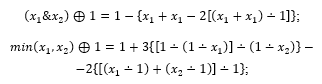
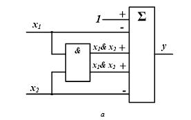
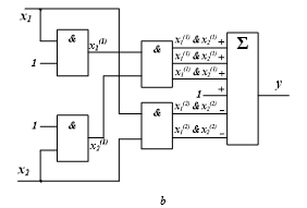
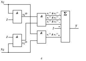 Figure 7: Functional schemes of the logical-arithmetic realization of the circular shift operation: a – two-valued, b – three-valued with a shift to the right, c – three-valued with a shift to the left.
The functional schemes corresponding to these expressions are shown in Figure 8, a, b, c.
The difference between the linear representations obtained from the arithmetic-logical representation is the possibility of physical realization. The authors of the article have obtained more than 25 patents for the circuit implementation of two-valued and three-valued logic circuits. Expansion of the arbitrary function into the algebraic sum of monotonic functions of the same value. To obtain the representation of the functions under consideration by the algebraic sum of monotonic functions, we expand them into the algebraic sum of monotonic functions within each value. For the two-valued function, the sequence graph of nondecreasing components has the form shown in Figure 9.
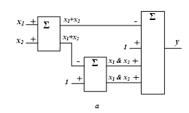
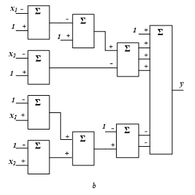
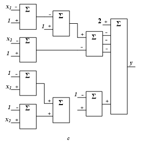 Figure 8: Functional schemes of the linear realization of the circular shift operation based on the truncated difference: a – two-valued, b – three-valued with a shift to the right, c – three-valued with a shift to the left.
![]() Figure 9: Sequence graph of nondecreasing components of the two-valued functions of two variables.
Figure 9: Sequence graph of nondecreasing components of the two-valued functions of two variables.
The structure of the expansion function of the equivalence into the algebraic sum of monotonic functions is given in Figure 10.
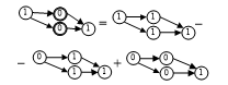 Figure 10: The structure of the expansion of the two-valued function into the algebraic sum of monotonic functions.
Here and below, the double circle marks the terms the values of which violate the monotonicity of the function.
It follows from the structure of the expansion that the representation of the function under consideration by the algebraic sum of monotonic functions has the following form Carrying out the similar transformations for the three-valued functions, the sequence graph of nondecreasing components of which is shown in Figure 11.
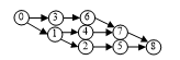 Figure 11: Sequence graph of nondecreasing components of the three-valued functions of two variables.
we obtain the following representations of the functions under consideration by the algebraic sum of monotonic functions:
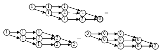 Figure 12: The structure of the expansion of the three-valued function into the algebraic sum of monotonic functions.
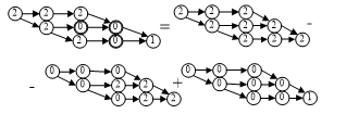 Figure 13: The structure of the expansion of the three-valued function into the algebraic sum of monotonic functions.
To obtain the equivalent representations of the expansion functions in linear analogs of the basis under consideration, we can proceed in the same way as with the functions themselves.
Expansion of the arbitrary function into the algebraic sum of smaller value.
We consider this operation with the help of the above transformation of the three-valued function , by unitary and weighted coding of the values of variables and functions.
In these cases, the encoding of variables and functions looks like this:
– unitary coding
| x | x2 | x1 |
| 0 | 0 | 0 |
| 1 | 0 | 1 |
| 2 | 1 | 1 |
Hence, it follows that for the unitary coding
weighted coding
| x | x2 | x1 |
| 0 | 0 | 0 |
| 1 | 0 | 1 |
| 2 | 1 | 0 |
It follows that at the weighted coding
Using the basic and its inverse matrix, we obtain the expressions for the two-valued expansion functions from the multivalued arguments:
for the unitary coding
for the weighted coding
The representation of the three-valued function by the two-valued ones for both versions of coding is given in Table 2.
Table 2 ─ The expansion of the three-valued function into the sum of the two-valued ones
| Unitary | Weighted | ||||
| 0 | 0 | 0 | 1 | 0 | 1 |
| 0 | 1 | 0 | 1 | 0 | 1 |
| 0 | 2 | 0 | 1 | 0 | 1 |
| 1 | 0 | 0 | 1 | 0 | 1 |
| 1 | 1 | 1 | 1 | 1 | 0 |
| 1 | 2 | 1 | 1 | 1 | 0 |
| 2 | 0 | 0 | 1 | 0 | 1 |
| 2 | 1 | 1 | 1 | 1 | 0 |
| 2 | 2 | 0 | 0 | 0 | 0 |
Replacing the three-valued variables with the two-valued ones in accordance with the rules given above, we obtain the two-valued expansion functions in the following form:
for the unitary coding
for the weighted coding
The functional schemes of the linear realization of the circular shift operation by the expansion into the sum of the two-valued functions are shown in Figure 14.
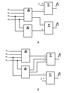 Figure 14: Functional schemes of linear realization of the circular shift operation by the expansion into the sum of the two-valued functions: a – on the basis of the unitary coding, b – on the basis of the weighted coding.
For the threshold representation and the subsequent threshold realization, it suffices to transform the equations obtained above into the threshold form. After completing this transformation, we get:
The functional schemes shown in Figure 15 correspond to these equations.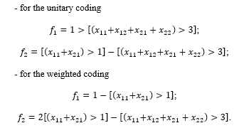
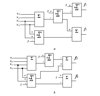 Figure 15: Functional schemes of linear realization of the circular shift operation by the expansion into the sum of the threshold two-valued functions: a – on the basis of the unitary coding, b – on the basis of the weighted coding.
The considered complex of transformations of logic functions in linear algebra proves useful in the design of digital structures for various applications.
5. Circuitry of the Linear Logic and Threshold Elements
- Basic functional nodes of digital logic elements. The implementation of the mathematically predetermined set of linear operations over the current signals requires the corresponding set of hardware. The circuit implementation of digital signal transformation functions based on the mathematical tool of linear algebra can be reduced to performing a relatively simple set of operations over the current signals. These operations include:
– conversion of the standard logic signals into the binary current signals matched with a reference current quantum I0;
– formation of the multivalued (non-binary) algebraic sums of current signals;
– performing the comparing operations of the received sums with the given levels of the reference currents.
These operations are typical for analog microcircuitry, therefore the main nodes of various functional elements can be constructed on the basis of the widely used analog structures. In addition, TTL circuitry and CMOS circuitry of these operations completely coincide.
The reference signal driver. It is designed to generate voltages that provide operational modes of elements of digital circuits synthesized in linear algebra. The schematic configuration of the driver is shown in Figure 16.
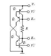 Figure 16: Reference signal driver.
The symmetric structure of the reference signal source is necessary for realizing the operations of converting “inflowing” and “flowing out” currents when creating the algebraic sums of variables in the mathematical tool of linear algebra. The only current-stabilizing two-terminal network, in particular case the resistor R, determines the levels of all reference signals. and are reference for setting the operating modes of current mirrors, and Еoff1 and Еoff2 – for setting the offset in the comparators of the currents. It can also be replaced by some semiconductor structure, and then the circuit becomes completely homogeneous and highly technological. It is also possible to make the two-terminal network R as an external element, which will allow changing the power consumption and the associated characteristics of the LSI during the debugging process.
The reference current source (RCS, Figure 17). The operating mode of the RCS is set by the reference voltages for the current sources and for the current sinks. The problem of constructing the RCS for digital circuits synthesized in linear algebra is completely similar to their problems in analog circuitry.
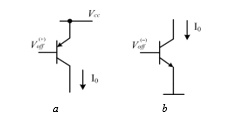 Figure 17: RCS of: a – the current current, b – the current sink.
The current follower (logic interpretation – direction converter). It is intended for the coordination of current directions at their algebraic summation. The schematic configurations of some versions of current followers in TTL circuitry are shown in Figure 18.
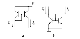 Figure 18: Current direction converter of: a – the sink current, b – the source current.
Circuitry of CMOS converters of the current direction is similar.
Algebraic current adder. It is an wired pack of the outputs of current mirrors with current directions determined by the mathematical representation of the realized logic function. To agree the operating modes of subsequent elements, it is provided with a buffer stage. The schematic configuration of the algebraic adder is shown in Figure 19.
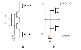 Figure 19: Algebraic current adder:
a – TTL circuit, b – CMOS circuit.
Current comparators. They are designed to determine the excess value of one of the input currents over the other. The schematic configurations of current comparators are given in Figures 20 and 21.
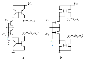 Figure 20: Comparator based on the truncated difference:
a – bipolar circuit, b – CMOS circuit.
In the circuit in Figure 21, the excess of one of the input currents (Ix1) over the other (Ix2) is determined by subtracting the second current from the first. One of the compared currents must be a source current and the second one – a current sink. Such a comparator is applicable for any logic value.
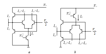 Figure 21: Current сomparator based on the comparison: a – for current sinks, b – for source currents.
In the circuit of Figure 21, a at Ix1 > Ix2 the left-hand transistor of the differential stage (DS) is closed and the current of the current mirror “leaves” through the right transistor of the DS. At Ix1 < Ix2, the right transistor of the DS is closed and the current of the current mirror “goes” through the left transistor. The output current of the DS I0 is the current sink.
In the circuit in Figure 21, b everything appears in a similar way, but with other current directions. Such a scheme is applicable for implementation of the two-valued digital structures.
In the previous section, the difference between the two-valued and multivalued implementations of the comparison operation is shown. In the latter case, it is possible to determine not only the fact, but the magnitude of the excess of one input signal over another one. In Figure 22 there is a circuit of the three-valued comparator performing such a modified comparison operation.
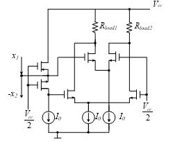 Figure 22: Modified multivalued comparator based on the comparison.
Such a scheme can be constructed for any value, increasing accordingly the number of parallelly operating DSs available to work with different values of currents.
Logic elements AND, OR, NOT. The representations of the operations of the two-valued basic functionally complete system in linear algebra using the truncated difference have the following form
The schematic configuration of these elements are shown in Figures 23, 24 and 25, correspondingly.
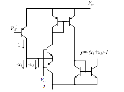 Figure 23: Schematic configuration of the element AND.
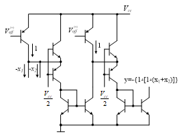 Figure 24: Schematic configuration of the element OR.
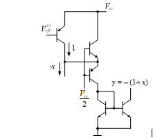 Figure 25: Schematic configuration of the element NOT.
Comparing the schemes shown in Figures 24 and 25, it is easy to see that removing the circuit of in Figure 25 from the scheme of Figure 24, we obtain the OR-NOT element.
Logic element “Inhibition”. The representation of the two-valued operation in linear algebra using the truncated difference has the following form
For the multivalued version, the two-valued inversion operation (in accordance with the accepted generalization ideology) should be replaced with the direct , or inverse min cycle operation, or left unchanged; i.e. in the following form . Other ideologies of generalization are also possible.
When using the comparison operation, the above expressions for operations of the functionally complete system take the following form
The implementation of these functions on the basis of the comparison operation can be performed with the help of the universal logic element (ULE), the schematic configuration of which is shown in Figure 26.
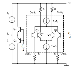 Figure 26: Basic scheme of the universal logic element.
At the inequality I1 < Ix1, the source difference current is generated at the node In.i of the ULE. It will “go” to the emitter of the transistor Q1, increasing the voltage at the first input (In.1) of the voltage comparator up to the value VOFF + Ube1, where Ube1 » 0.7V – voltage of the open emitter junction of the transistor Q1. In this case, the input transistors Q3 and Q4 of the voltage comparator (VC) switch to the inverse states – the collector current of the transistor Q3 becomes zero, and the transistor Q4 starts to transmit the current of the reference current source I2 = I0 to the second current output (Out.i2) of the ULE.
Thus, depending on the difference in the numerical values of the currents I1 and Ix1, the output currents of the ULE take one of two values: either it is the current of the reference current source I1 = I0 or “zero” (no current). Since the current I1 ( ) is equal to the current quantum I0, then in one of the current outputs of the voltage comparator a standard current signal I0 of one of the logic levels is generated, and in its second output – an inverse logic level signal. Depending on the numerical values of I1 (I1 = 0,5I0, I1 = I0, I1 = 1,5I0) and the methods of forming the input current signals of the ULE (Figure 26), various logic functions can be performed, for example
In the last two expressions .
The element considered above can be used as a logic element, or as a threshold one; i.e. the generalization of the ordinary and threshold logics in the linear representation is very close. In the first case, unitary variables are fed to the inputs of the element. Besides, the number of inputs must correspond to the number of the variables. In the second case, the weighted sum of the variables should be fed to the “positive” input, and the constant equal to the calculated threshold value should be fed to the “negative” input. It is noteworthy that the described element can serve as an element of the homogeneous matrix, which can be used for matrix synthesis of the current digital structures. In addition, it is possible to construct universal current logic modules on its basis.
Similarly, the Ban operation can be expressed in terms of the truncated difference as
Cut formers. In fact, the cut former is an input signal limiter at the given level. As a former, the schemes that implement the operations (upper cuts) and (lower cuts) can be used.
Buffer output stage. The combination of the algebraic adder and the current follower (converter) can be applied as a buffer output stage. With the help of the latter, the given number of the output circuits can be arranged to provide the required output branching factor.
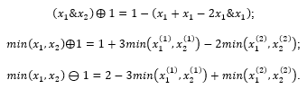
- The synthesis of logical schemes. Let’s consider it through the example of the two-valued and multivalued circular shift elements discussed above. They can be represented as a single operation in the form or , or as a compound operation, i.e. as the sequential combination of operations working on one another or and operations ⨁1 or ⊖1, that is, in the form or . We confine ourselves to the synthesis of the circuits using the operation .
In accordance with [17-32], the synthesis of the functional scheme corresponding to any logic function consists in multiplying the row-vector of the values of the function by the inverse basic matrix and obtaining the expansion vector of the function from the selected basis, and then recording the representation of the function as a weighted sum of the basis vectors. We perform the synthesis of the selected schemes using the basis presented below.
In the two-valued case, the element AND-NOT has an arithmetic-logical representation, described by the expression
which can be represented by the truncated difference in the following form
and by comparison – in the following form
The schematic configurations of the elements can be constructed directly according to these expressions. Figure 27 shows an element scheme based on the truncated difference.
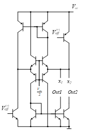 Figure 27: Schematic configuration of the element of AND-NOT based on the truncated difference.
We proceed similarly for the three-valued schemes in the first case (by the single operation). Using the basis
with the inverse matrix
we obtain the following results for the single operation:
– resolution vectors
– linear expressions of the functions
The schematic configuration of the element of the right circular shift, synthesized directly from the above expression, is shown in Figure 28.
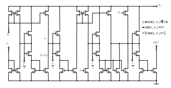 Figure 28: CMOS element of the right circular shift.
The schematic configuration of the element of the left circular shift, synthesized directly from the expression given above, is given in Figure 29.
Similarly, for the compound operation:
– the resolution vector
– linear expression of the function
 Figure 29: CMOS element of the left circular shift.
Similarly, for the compound operation:
– the resolution vector
– linear expression of the function
– resolution vectors of the operations or :
– linear expressions of the functions:
The schematic configuration of the element , synthesized directly from expression (5) discussed above, is shown in Figure 30.
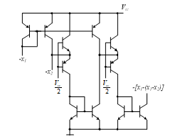 Figure 30: Schematic configuration of the element .
The schemes of the elements of the left and right cycles are shown in Figures 31 and 32.
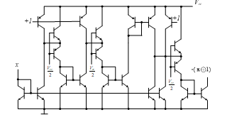 Figure 31: Element of the right cycle.
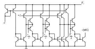 Figure 32: The element of the left cycle.
To obtain the final expression in the procedure for synthesizing a particular logic element, it is sufficient to substitute , for x in the last expression, and for the circuit implementation, – use the above implementation of the function , then connect the circuit or to its output.
- To demonstrate the possibilities of the sequential circuit synthesis, we use the results of the logic element synthesis obtained above.
Boolean approach to the logic synthesis of triggers consists in supplying the memory element with a control circuit that provides a specified law for the operation of a specific type of the trigger. In the two-valued case, the memory element is a scheme of two 2AND-NOT elements covered by the positive feedback (Figure 33):
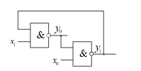 Figure 33: Two-valued trigger (memory element).
The linear synthesis of the two-valued triggers in linear algebra does not differ fundamentally from Boolean synthesis [17]. The schematic configuration of the trigger can be constructed in the same way as it is done in Boolean logic (for example – Figure 34):
When moving to higher values while remaining the general idea of synthesis, it is necessary to use the elements and operations that are a generalization of the two-valued operations and logic elements. The operations min (x1,x2) and max (x1,x2) are generalization of the operations & and ˅ is. As for the inversion operation, to generalize it for a multi-valued case it is convenient to represent it in the form of and generalize it by a circular shift of Post (left or right). The general functional configuration of the memory element based on three-valued elements of the direct circular shift is shown in Figure 35.
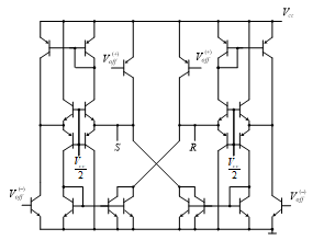 Figure 34: Two-valued RS-flip-flop in the studied basis based on the truncated difference.
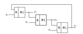 Figure 35: Three-valued trigger on the elements of the direct circular shift.
The general functional configuration of the memory element based on the three-valued elements of the inverse circular shift is given in Figure 36.
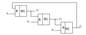 Figure 36: Three-valued trigger on the elements of the inverse circular shift.
The functional schemes of the memory elements of higher significance look similar.
Thus, to construct any multivalued memory element, it is necessary to synthesize the elements of direct and inverse circular shifts. To create a trigger of the given type (D-, RS-, JK-, etc.), it is required to equip the memory element with the corresponding control circuit.
The control circuits of the memory elements are constructed on the base of the verbal description of the operation of a specific type of the trigger. The result of the analysis of this description is the detection of logic control functions for each input of the memory element.
For example, the RS-flip-flop operates according to the following algorithm:
– the values of the input signals S = R = k –1 correspond to the storage mode;
– the signal S increases the trigger state index relatively to the current state towards the state k-1, and the signal R reduces the state index towards the state “0”;
– the value of the state index change is equal to the value of the input signal: the signal equal to 1 can increase (or decrease) the current state index by 1, the signal equal to 2 – by 2, etc .; besides, the signal S increases the trigger state index to the state k-1, and the signal R reduces the state index to “0”; the state change on the cycle is impossible (we leave this for the universal triggers!);
– to change the trigger state index relatively to the current state i, the signal S can take values from 1 to k-1-i (larger values are equivalent to the value of k-1-i). Similarly, the signal R can take the values from 1 to i -1 (larger values are equivalent to the value i -1);
– all combinations are inhibited combinations of values of the input signals, except 0 – k-1, 1 – k-1, k-2 – k-1, k-1 – k-1, k-1 – 0, k-1 – 1, …, k-1– k-2.
Now it is possible to synthesize the logic function of the control circuit of the RS-flip-flop. Its output signal is a multi-valued signal x that sets the next state of the memory element, and the input signals are multivalued signals S and R, as well as the current trigger state index.
The truth table of the control functions of the three-valued RS-flip-flop, compiled on the basis of this description, has the following form:
| S | R | ||||
| 0 | 2 | 0 | 1 | 1 | |
| 1 | 2 | 1 | 0 | 1 | |
| 2 | 2 | 1 | 1 | 1 | |
| 2 | 1 | 1 | 0 | 1 | |
| 2 | 0 | 1 | 1 | 0 |
From the last table it follows that the logic functions for controlling the state of the memory element are described as follows:
The combination of the memory element circuit and the control circuit results in the implementation of the trigger of the given type.
Similarly, arguing, we can obtain the logical control functions of the three-valued D-flip-flop:
In the same way, we can obtain the description of the control system of any other multivalued trigger, the number of types of which is certainly greater than the two-valued one.
Combining the control circuit and the memory element in series, it is possible to obtain the schematic configuration of the trigger of any type and any value.
6. Conclusion
The mathematical tool of linear algebra can be newly applied in problems of logic synthesis and circuit implementation of the current digital structures.
- Linear algebra:
– enables to create not only a two-valued, but also a really properly functioning multivalued element base for digital signal processing devices;
– conduces the design of the digital element base with the improved technological, technical and operational characteristics (in comparison with the potential logic based on Boolean algebra);
– can serve as a basis for creating LSI on the basis of matrix fields of homogeneous elements (as in modern Altera design systems, etc.);
– improves the reliability of current digital LSIs synthesized on its basis, under extreme operating conditions (temperature, radiation, in-phase interferences, etc.).
- Two-valued and three-valued triggers based on cyclic shift elements are considered. It is shown that in the transition to greater significance, while preserving the general idea of synthesis, it is necessary to use operations that are generalizations of two-valued operations and the corresponding logical elements.
- The presents a basic set of current logic elements for the devices of automation, which allows solving the problems of transformation of the current signals in a different and more efficient way.
- In the schemes of the developed class is provided a differential representation of the output signal that minimizes the effect of temperature and radiation on their basic parameters.
Conflict of Interest
The authors declare that there is no conflict of interests regarding of publication of this paper.
Acknowledgment
The research is carried out at the expense of the Grant of the Russian Science Foundation (project № 16-19-00122).
- N. Prokopenko, N. I. Chernov, V. Ya. Yugai, N. V. Butyrlagin, “The Element Base of the Multivalued Threshold Logic for the Automation and Control Digital Devices,” on International Siberian Conference on Control and Communications, SIBCON-2017, Astana, Kazakhstan, 29-30 June, 2017.
- S. Karpenko, “Multi-valued logics (monograph),” in series “Logics and computer”, Moscow, issue 4, 1997, 223 p. (in Russian).
- A. Zalmanson, “Fourier transform, Walsh, Haar and their application in management, communications and other fields,” Moscow, Nauka, Fizmatlit publ., 1989, 496 p. (in Russian).
- S. Vykhovanets, V. D. Malugin, “Spectral methods in logical management,” Proceedings of the 2nd international scientific-technical conference “Modern methods of digital processing of signals in spelthorne, monitoring, diagnosis and control (OS 1998)”, Minsk, 1998, pp. 56-59. (in Russian).
- Thornton, “Mixed representation of the multi-Boolean function spectra and critical charts,” Automatics and telemechanics, 2004, vol.6, pp. 188-200. (in Russian).
- I. Ivchenko, V. A. Mironov, “Some questions of spectral analysis of random Boolean functions with constraints,” Discrete mathematics, 2013, vol. 1, pp. 90-110. (in Russian).
- N. Kondratyev, A.A. Shalyto, “Implementation of systems of Boolean functions using arithmetical polynomials,” Automatics and telemechanics, 1993, vol. 2, pp. 114-122. (in Russian).
- D. Malyugin, “The parallel logic computation by the arithmetic of polynomials,” Moscow, Nauka, Fizmatlit publ., 1997, 192 p. (in Russian).
- V. Sokolov, O. N. Zhdanov, A. A. Ayvazyan, “Methods for the synthesis of the algebraic normal forms of functions of multivalued logic,” System analysis and applied Informatics, No. 1, 2016, p. 69-76. (in Russian).
- Dertouzos, “Threshold logic,” Moscow: Mir publ., 1967. (in Russian).
- G. Nikonov, “Threshold representations of Boolean functions,” Review in applied and industrial mathematics, Series discrete mathematics, 1994, vol. 1, No. 3, pp. 402-457. (in Russian).
- A. Butakov, “Methods of synthesis of relay devices,” Moscow: Energy publ., 1970, 328 p. (in Russian).
- N. Vavilov, etc. The Synthesis of threshold circuits for the elements – Moscow: Soviet Radio publ., 1970, 368 p. (in Russian).
- Muroga, “Threshold logic and its applications,” New York: Wiley, 1971.
- H. Piers, “Failure Tolerant computer dezign,” New York and London: Academic Press, 1965.
- G. Nikonov, N. Nikonov, “Features of threshold concepts k-valued functions,” Tr. on discr. mod., 2008, volume 11, issue 1, pp. 60-85. (in Russian).
- Hastad, “On the size of weights for threshold gates.” SIAM J. Discr. Math. 1994.
- I. Chernov, “Foundations of Logic Synthesis of Real Numbers Field Digital Structures”, Taganrog: TRTU, 2000, p.146 (in Russian).
- I. Chernov, “Boolean Linear Space as an Algebraic Structure for Logic Synthesis of Digital Units,” The News of TRTU, 2003, No.1, pp. 215-220. (in Russian).
- I. Chernov, “Structural Synthesis of Digital Units within Boolean Linear Spaces,” The News of TRTU, 2003, No.2, pp. 73-76. (in Russian).
- I. Chernov, “Efficiency of Application of the Body of Linear Spaces within Logic Synthesis,” Conferences on Artificial Intelligence Systems (IEEE AIS’ 05)’ and Intelligent CAD (CAD-2005, vol.1, pp. 420–424. (in Russian).
- I. Chernov, “Logic Design of Digital Structures on Controlled Current Generator,” The News of TREU, 2005, No.11, pp. 77- 83. (in Russian).
- I. Chernov, “The effectiveness of the apparatus of linear spaces in the logic synthesis of digital structures,” Proceedings of the international scientific and technical conferences “Intelligent systems (IEEE AIS’05)” and “Intelligent CAD (CAD-2005”,vol.1, pp. 420 –424. (in Russian).
- I. Chernov and V. Ya. Yugai, “Nonclassical Synthesis of Digital Structures by Tools of Analogous Circuits Engineering,” Problems of Today’s Analogous Circuits Engineering: The Collected Articles of IX International Scientific-Practical Seminar edited by N.N. Prokopenko, Shakhty, Rostov-on-Don Region: FSBEU HPE “SRSUES” Publishers, 2012, pp. 138 – 143. (in Russian).
- N. Prokopenko, N. I. Chernov, V. Ya. Yugai, “Base Concept of Linear Synthesis multi-Valued Digital Structures within Linear Spaces,” Proceedings of The IS&IT13 Congress, The Scientific Edition in four volumes, Moscow: PhisMathLit publ., 2013, v. 1, pp. 284-289. (in Russian).
- N. Prokopenko, N. V. Butyrlagin, N. I. Chernov, V. Ya. Yugay, “Synthesis of binary triggers in the apparatus of linear algebra,” Izvestiya SFedU. Technical Sciences. No. 2. 2015, pp. 115-125. (in Russian).
- N. Prokopenko, N. I. Chernov, V. Ya. Yugai, N. V. Butyrlagin, “Linear synthesis of k-valued digital components of the base current logical signals: the principle of generalization”, Problems of development of perspective micro and nanoelectronic systems – 2016. Proceedings / under the General editorship of academician RAS A.L. Stempkovskogo. Moscow: IPPM RAS, 2016. (in Russian).
- I. Chernov, V. Y. Yugai, N. N. Prokopenko, N. V. Butyrlagin, “Basic concept of linear synthesis of multivalued digital structures in linear spaces,” Proceedings of IEEE East-West Design and Test Symposium, EWDTS 2014, art. no. 7027045. DOI: 10.1109/EWDTS.2014.7027045
- N. Prokopenko, N. V. Butyrlagin, N. I. Chernov, V. Ya. Yugai, “The linear concept of logic synthesis of digital IP-modules of control and communication systems,” 2015 International Siberian Conference on Control and Communications, SIBCON 2015 – Proceedings, art. no. 7147182. DOI: 10.1109/SIBCON.2015.7147182.
- N. Prokopenko, N. V. Butyrlagin, N. I. Chernov, V. Ya. Yugai, “Basic linear elements of k-Valued digital structures,” 2016 International Conference on Signals and Electronic Systems, ICSES 2016 – Proceedings, pp. 7-12. DOI: 10.1109/ICSES.2016.7847763.
- N. Prokopenko, N. I. Chernov, V. Yugai, N. V. Butyrlagin, “The element base of the multivalued threshold logic for the automation and control digital devices,” Proceedings of 2017 IEEE International Siberian Conference on Control and Communications, SIBCON 2017, art. no. 7998508. DOI: 10.1109/SIBCON.2017.7998508.
- N. Prokopenko, N. I. Chernov, V. Yugai, N. V. Butyrlagin, “The multifunctional current logic element for digital computing devices, operating on the principles of linear (not boolean) algebra,” Proceedings of 2016 IEEE East-West Design and Test Symposium, EWDTS 2016, art. no. 7807723. DOI: 10.1109/EWDTS.2016.7807723.
- I. Nechaev, “Numeric system,” Moscow: Education publ.,1975, 199 p. (in Russian).
- A. Gorbatov, “Foundations of discrete mathematics,” Moscow: Higher school publ., 1986, 311 p. (in Russian).
No related articles were found.