Flexible lengthening-shortening arm mechanism for fishery resource management

Adv. Sci. Technol. Eng. Syst. J. 2(6), 290–301 (2017);
 DOI: 10.25046/aj020636
The goal of this study was to use underwater robots instead of a diver’s observations to monitor and record the condition of an obstructed seabed in a shallow area. It is difficult to investigate marine resources that exist in deep water shaded by rock due to large and/or small rocks on the seabed. To solve these problems, we newly constructed a flexible lengthening-shortening arm with a small camera unit for an underwater robot to assist in the management of fishery resources. In this paper, we describe the concept and configuration of the newly developed arm mechanism using a sliding screw mechanism to overcome obstacles by changing arm posture in a two-dimensional plane, and we demonstrate the experimental results of a path-tracing controller for the rear links. The results were that the maximum deviations between the target path and the tracing path were less than 4.0% of the total width of the arm mechanism. These results suggest that the newly developed path-tracing algorithm is effective for our flexible lengthening-shortening arm mechanism.
1. Introduction
This report is an extension of work that was originally presented at the 2017 IEEE International Conference on Mechatronics and Automation (ICMA) [1]. Extended points are as follows; (a) the geometric configurations and control parameters for an unique slider-screw mechanism of our system in Section 2.2.3, (b) waterproof design for the slider-screw mechanism in Section 2.2.4, (c) an operational test on land to clarify the validity of the flexible lengthening-shortening arm mechanism in Section 3.1, (d) an explanation of the details of the path-tracing algorithm in Section 4.2.3 and Appendix, and (e) improvements of the movement error occurred in previous work [1].
Underwater robots, such as autonomous underwater vehicles (AUVs) and remotely operated vehicles (ROVs), were developed to reduce the big burden on fishermen in managing fishery resources and/or the cost of submarine operations and risk to human life (e.g.; AUV for work in shallow waters and coastal areas [2], reduce the burden on divers [3], achieving the core sampling at shallow seabed [4], and achieving the video transect method instead of divers [5]). Generally, underwater robots are equipped with cameras to monitor and record the condition of the seabed rather than relying on a diver’s observations. In the case of shallow sea areas, such as surf zones, there are many rocks and marine algae. Although these areas are useful as growth environments of fishery resources, it is assumed that the view of the camera is hindered and/or the robots cannot approach the target objects closely. In addition, it is difficult to investigate rock shadows, which cannot be penetrated by underwater robots, and the shellfish living deep within them.
There is a possibility that a survey could not be achieved using current robot arms (e.g.; dual arm operation [6] and tele-operated manipulators installed to ROV [7]). Instead of using robot arms, developing snake-type robots is one solution. Snake robots can search for and investigate targets, avoiding multiple obstacles by their serpentine motion in narrow environments where humans cannot intrude. Previously, many researchers had been developing snake-type robots for investigating unknown environments and searching for disaster sites (e.g.; review of snake-type robots [8], tutorial of snake-type robot [9], and carrying out the inspection work [10]). Also, an amphibious snake-type robot, which moves in a serpentine motion for generating the forward propulsion in water, has been studied [11]. With this unique motion, however, it is necessary for the robot to keep thrusting in order to stay in place in shallow areas where wave disturbances occur from all directions. Without any propulsion force for forward movement by a serpentine motion, a mobile robot equipped snake-type arm mechanisms had been studied (e.g.; surveying robot equipped with snake-type arm on wheel robot [12], assembling an aircraft using a snake-type arm mounted on a traditional industrial robot arm [13], and linear motion mechanism mounted on base of snake-type arm [14]). When entering the camera at the tip of the arm into the narrow space, the snake-type arm changes its attitude so as to avoid obstacles and the intrusion operation (forward approach action) is in charge of the base unit. In order to investigate a narrow area in the shallow sea using AUV or ROV equipped an arm with snake-type mechanism, it is necessary to take forward motion while maintaining posture and position against the tidal current near the seabed. Therefore, we assumed that a snake-type arm, which had a forward movement mechanism and installed to AUV and/or ROV, is effective for investigating narrow areas in shallow sea. Hence, the purposes of this study were: 1) to construct a new robot arm that utilizes the features of a snake-type robot’s obstacle avoidance, and 2) to evaluate the autonomous path-tracing algorithm to achieve obstacle avoidance at the part of the rear-link mechanism. In this paper, Section 2 outlines our newly developed arm mechanism and the results of the operation test. In Section 3, we propose a path-tracing algorithm of the rear-link mechanism required for obstacle avoidance and show the effectiveness of this algorithm experimentally.
2. Flexible lengthening-shortening arm mechanism (FLSAM)
2.1. Design specifications
We selected the following design specifications for the newly developed flexible lengthening-shortening arm mechanism (FLSAM):
- The FLSAM can avoid obstacles,
- The FLSAM can reach into rock shadows and penetralia,
- The FLSAM can approach target objects closely, and
- The FLSAM can obtain photos and movies for further analysis.
To satisfy the required specifications of the rotational and translational degrees of freedom, the FLSAM’s design considers the following points:
A1. To avoid obstacles, the FLSAM should be equipped with rotational degrees of freedom,
A2. To reach into rock shadows and go near the target, the FLSAM should be able to expand its arm length by translational degrees of freedom, and
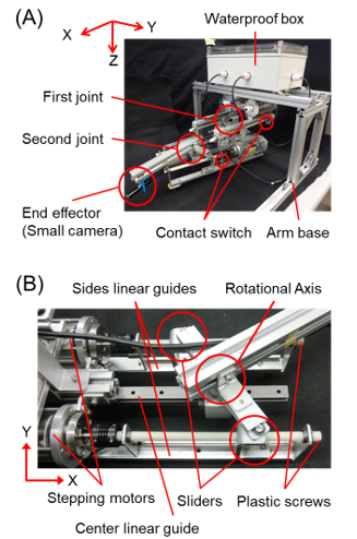 Figure 1: (A) Overview of the newly developed flexible lengthening-shortening arm mechanism, “FLSAM”; (B) mechanical details around the second joint of the FLSAM
A3. To obtain photos and movies, a small video camera should be installed on the FLSAM.
2.2. Configuration of the FLSAM
- Overview of the FLSAM
Figure 1A shows an overview of the FLSAM, and the specifications are denoted in Table 1. Each joint consists of two stepping motors (PKP213D05A, ORIENTAL MOTOR Co., Ltd.), two plastic screws (MB-RENY-M8-300, MISUMI Corporation), and three linear guides (for both sides: NK-02-17-1-220-LLYZ, igus k.k.; for the center: TK-04-12-1-250, MISUMI Corporation). Each linear guide was in parallel, and sliders were installed on both sides of the linear guides. To achieve rotational degrees of freedom, the rotational axis was set at the center linear guide. As to the detailed structure of the joint, the appearance of the second joint is shown in Figure 1B. Contact switches (PTP5M3CB-L, MISUMI Corporation) were installed to detect the origin of the
| Table 1: Specifications of the FLSAM | |
| Total height [mm] | 190 |
| Shortened length [mm] | 290 |
| Maximum lengthened condition [mm] | 560 |
| Total width [mm] | 140 |
| First joint stroke [mm] | 90 |
| Second joint stroke [mm] | 180 |
| Range of motion [deg] | Plus/minus 45 |
| Total weight [kg] | 3.9 |
| Sensors | Small camera
Contact switch |
sliders and to prevent an overrun. A small waterproof camera (WPMISC7M, THANKO Co., Ltd.) was equipped to record photos and movies from the end effector. Electric circuits with an AVR microcomputer (Arduino Uno R3, Arduino AG) were placed in a waterproof box (SPCM13-18-10-T, MISUMI Corporation).
- Sliding screw mechanism to achieve rotational and translational degrees of freedom of the FLSAM
When constructing an arm with the simultaneous motion of the translational and rotational degrees of freedom, it is natural to couple the translational and rotational mechanisms. However, the arm mechanism increases in size due to the increased number of joints when the translational and rotational joints are arranged separately. Therefore, we adopted a sliding screw mechanism to achieve the translational and rotational degrees of freedom in one joint. The sliding screw mechanism could be expected to reduce the size and number of joints. Moreover, it could be said of this mechanism that (1) power consumption is low because it is not necessary to maintain the posture, and (2) it can operate in water without a lubricant [15].
Figure 2A–C shows the schematic of the sliding screw mechanism installed in the FLSAM. We arranged two sliding screws for one joint, and the slider part moves forward and backward with respect to the rotational volume of the first and second actuators. The FLSAM installed two sliding screw mechanisms; in total, four degrees of freedom were achieved. The changes in the stroke length of each sliding screw mechanism were defined by the number Pk [pulse] and frequency Ak [pulse/s] of pulses’ input to the stepping motor, as
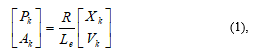 where, k is the number of the slider (1 and 2 for the first joint, 3 and 4 for the second joint), Xk [mm] is the stroke length of each slider, Vk [mm/s] is the moving velocity of each slider, Le [mm] is the lead of the screw, and R [pulse] is the number of pulses per
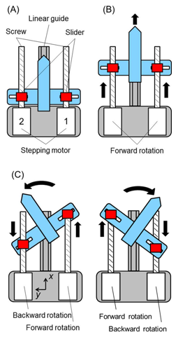 Figure 2: Schematic figure of the sliding screw mechanism installed in the FLSAM; (A) initial condition, (B) lengthened condition, (C) flexible condition
revolution of the stepping motor. In the FLSAM, the Le is set at 1.25, and the R is 200.
- Geometric configuration of the sliding screw mechanism
Figure 3 is the schematic of the geometric constraints and the definition of the control parameters by the sliding screw mechanism for the FLSAM. The Oi-1Xi-1Yi-1 joint coordinate system was set at the base of the sliding screw mechanism. The
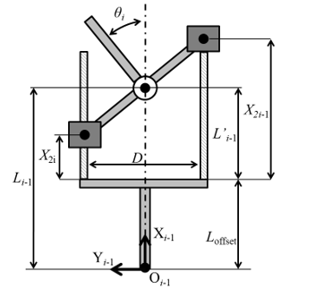 Figure 3: Schematic figure for the parameters of the sliding screw mechanism
 Figure 4: Geometric relationships between the joint range of motion and the joint stroke length; (A) first joint, (B) second joint
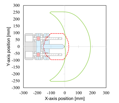 Figure 5: Schematic figure of the range of motion of the FLSAM; red broken line denotes the range of motion for maintaining the maximum flexibility, green line denotes the maximum range of motion
link length, Li-1, and the joint angle, θi, were controlled by right- and left-moving sliders. The L’i-1, Li-1, and θi were calculated as
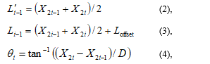 where L’i-1 (i=1, 2) is the link length while lengthening, shortening, and/or rotating. X2i-1 is the slider position at the side of the positive in the y-axis, X2i is the slider position at the side of the negative in the y-axis, and D is the length between the two sliders. The position of the end effector of the FLSAM was operated by combinations of the Li-1 and θi. The movement speed of both sides of the slider is determined so that the operation time is the same according to the Li-1 and θi, since only the slider on one side works as a singular point.
The sliding screw mechanism has a unique characteristic, in which the maximum range of motion of a joint angle varies with the changes in the link length, as shown in Figure 4. Both maximum joint ranges of motion were set at plus/minus 45 degrees; however, the maximum joint range of motion is 0 degrees when the left and right sliders are at the minimum and/or the maximum position of the link length simultaneously. In addition, these maximum joint ranges of motion were independent parameters, so that it is possible to take the most flexible posture from 43 mm to 47 mm in the first joint and from 43 mm to 137 mm in the second joint. Figure 5 shows a range of motion of FLSAM. In this study, the range of motion was set at the inside area depicted by red line, which maintain the maximum flexibility of FLSAM (joint ranges of motion was at ± 45 deg). When operating beyond this range, the maximum joint ranges of motion become small and the flexibility of the FLSAM decreases.
- Waterproof structure of the sliding screw mechanism
The main parts of the FLSAM (sliding screws, sliders, guide rails, and a small camera) are highly water resistant. Cable entry and exit of the waterproof box equipped with an electrical system were waterproofed by cable grounding. Four stepping motors were waterproofed using custom-designed cylindrical housings, as shown in Figure 6. Basically, the housing is made watertight by careful fitting of the acrylic tube, aluminum lid, and O ring. The rotary shaft was waterproofed by combining stainless steel bushes, resin bushes, and a sealing material.
- System configuration of the FLSAM
Figure 7 shows the system configuration of the FLSAM. The FLSAM’s control program was constructed using commercialized software, LabVIEW 12.0.1 (National Instruments Japan Corp.). All control signals from the controller were communicated to Arduino via a serial port, and Arduino then calculated the control signals for the motor drivers (SFE-ROB-12779, SWITCH SCIENCE). Contact switch signals are the only feedback signals to determine the initial and/or the maximum lengthened condition of the FLSAM.
3. Operational tests of the FLSAM
3.1. Operational test on land
In order to check whether lengthening-shortening and flexion motions by a sliding screw mechanism of design requirement for image acquisition by a small camera are possible, a ground motion test was carried out. As targets for image acquisition, models of aquatic organisms (turtle, shark, dolphin, and seahorse) and an obstacle were placed randomly. The seahorse model was placed in the shadow of an obstacle that would be a blind spot from the initial posture of the FLSAM. One of the objects of this investigation is abalone, and the catch size is defined as more than 90 mm. For this reason, an imaging target model in this operational test was also the same size of abalone. Each mode size is shown in Table 2. Hence, the FLSAM avoided obstacles due to the lengthening-shortening and flexion motion of the arm and eventually was able to discover the seahorse model. The amount of the stroke length and velocity of each slider of the FLSAM was given as a numerical input from a PC, and the operator checked the posture of the FLSAM and the camera image visually. Figure 8 shows a typical image acquisition and a birds-eye view of the FLSAM operation. In the process of finally photographing seahorses, images were acquired, in order, of the turtle, shark, dolphin, and then the seahorse in this arrangement. When the base unit is stable, FLSAM is not affected by posture change due to disturbance in water because of the characteristics of the sliding screw mechanism. Therefore, when the FLSAM achieves the ideal motion on land, the FLSAM can perform the same operation even in water as on land. It was confirmed that the FLSAM can achieve lengthening-shortening and flexion motions as demanded of the design. Also, image acquisition with a small camera was achieved.
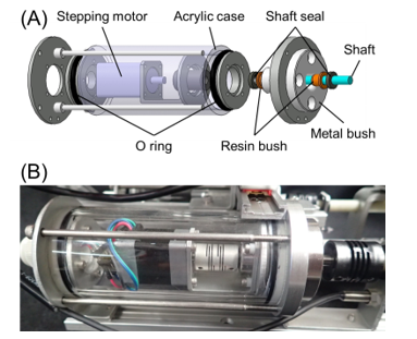 Figure 6: Waterproof motor housing; (A) exploded view of the designed housing, (B) photo of the manufactured housing
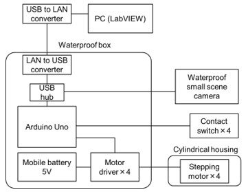 Figure 7: System configuration of the FLSAM
| Table 2: Each mode size | |||
| Models of aquatic organisms | High [mm] | Length [mm] | Width [mm] |
| Turtle | 40 | 90 | 70 |
| Shark | 60 | 170 | 90 |
| Dolphin | 50 | 110 | 40 |
| Seahorse | 60 | 40 | 30 |
3.2. Operational tests in water
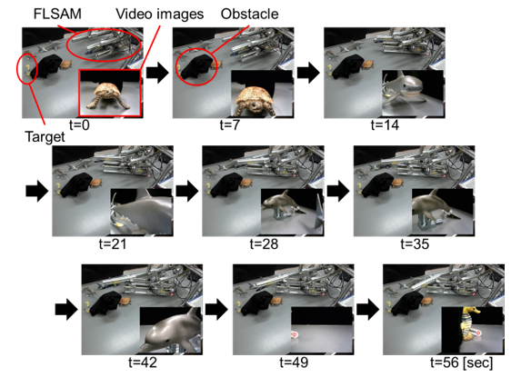 Figure 8: Time series of the state of the operational test conducted on land
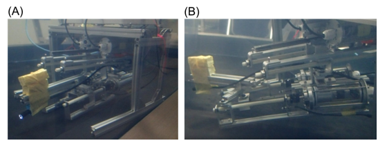 Figure 9: Typical states of the operational test in water; (A) the initial condition, (B) left-side flexed condition Figure 9: Typical states of the operational test in water; (A) the initial condition, (B) left-side flexed condition |
The experiment was carried out in static water conditions (the water tank was 1.57 m deep × 1.2 m wide × 1.27 m high). The FLSAM was placed on the floor of the water tank in its initial condition, and then any arbitrary lengthening/shortening and/or flexion motion was operated manually. To make sure that the sliding screw mechanism of the FLSAM functions properly in water, lengthening-shortening and flexion motions were tested multiple times with reciprocated motions. Further, in order to ascertain whether there is a possibility of water leak into the motor housing due to vibration of the motor and/or the rotation of the shaft, the operation speed is changed while the underwater test continues. Also, video images were checked on the PC simultaneously to determine whether it is possible to acquire images via the small underwater camera installed. The operation of FLSAM was confirmed from the outside of the water tank.Although it was confirmed that FLSAM could operate without any problems during the ground test, FLSAM was developed to be used in water. Therefore, it was necessary to conduct verification tests to confirm whether it can function properly underwater. Hence, this experiment was planned (1) to check the underwater motion, (2) to obtain camera images, and (3) to check the waterproof performance of the FLSAM.
From outside the water tank, it was confirmed that, for 30 minutes, the FLSAM performed every operation on the floor of the water tank. In addition, no water leaked into the housing. Figure 9 shows the typical condition during the operation tests of the FLSAM in water: (A) is the initial condition, and (B) is in the left-side flexed condition. In water, the FLSAM achieved the desired behavior commanded by the operator. However, as the arm lengthened, the FLSAM unexpectedly became tilted, and the small camera at the tip of the arm contacted the floor. This was due to the movement of the center of gravity that occurred when the arm was lengthened. Therefore, it is suggested that attitude control by the support base is required to acquire a stable image using the FLSAM.
4. Autonomous path-tracing experiment for rear-link mechanisms
4.1. Purpose of the path-tracing experiment
Path planning and tracing are key issues for investigating the shadows of rocks. In the case of the FLSAM, path planning and its tracing algorithm should also be installed to achieve obstacle avoidance and to reach into the depths of rock shadows to enable surveying. Methods of controlling a flexible robot arm with a retractable mechanism have been studied (e.g.; series studies of path-tracking control of a moray-type robot arm by same group [16–19], expands and/or contracts arm mechanism [20], and path tracking control of underwater snake-type robot [21]); however, it is impossible to plan a path in environments where the camera cannot obtain data due to blind sports and/or deep rock shadows.
Previous studies have developed methods of manipulating the tip of the arm using a camera image to intrude into an unknown environment (e.g.; surveying robot to avoid obstacles based on screw principle [22], double headed snake-type robot [23], and remotely operated snake-type robot [24]). The FLSAM that can enter unknown environments, such as rock shadows in water, is considered to be effective. Therefore, we adapted to control the FLSAM manually using only the video data obtained from the small installed camera. Figure 10 shows the schematic figure entering the rock shadows by changing the posture of the FLSAM. The operator decides the traveling direction of the tip of the arm using the obtained video data and then manipulates the traveling direction forward/backward and left/right so that only
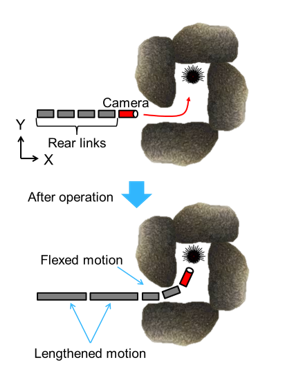 Figure 10: Schematic figure of entering the rock shadow by changing the posture of the FLSAM
the tip of the arm should be controlled manually. This means that the rear links would autonomously follow the movement path of the arm tip. Hence, the purpose of this experiment was to evaluate the accuracy of path tracing of the rear links using the FLSAM’s control path-tracing algorithm.
4.2. Path tracing in the rear-link parts of the FLSAM
- Definition of the rear-link in FLSAM
FLSAM has two sliding screw mechanism joints. That means that if the second link of the FLSAM equipped with the small camera is defined as the arm tip, the rear link is only the first link. However, it is difficult to evaluate the validity of the path-tracing algorithm by measuring the movement of one link. Hence, as shown in Figure 11AB, the virtual arm tip is defined as existing at the tip of the second link of the FLSAM, and the first link and the second link of the FLSAM are set as the rear links.
- Target path defined by the Spline interpolation curve
The first and second rear links of the FLSAM autonomously trace the tip’s moving path. In this research, we prepared the target path under the assumption that the tip’s moving path is generated by the movement of the virtual tip, and the first and second links of FLSAM trace this virtual path. For the target path, a cubic Spline interpolation curve capable of creating a two-dimensional curve in space was used. The details are described in Appendix-1; however, the first derivatives of the start point of the Spline curve are set to 0 in the boundary condition (A5). With respect to this definition, the slope of the Spline curve at the start point becomes 0. Therefore, the Spline curves of the target path and the X axis are continuous at the origin of the global coordinate system, and discontinuity of the arm joint angle can be avoided.
- Development of a path-tracing algorithm in the rear-links of the FLSAM
Figure 11C shows a schematic of path tracing in a rear link of the FLSAM. In this study, the rear links of the FLSAM trace the Spline curve created as the target path to evaluate the validity of the path-tracing algorithm. In order to trace the target path, it is necessary to calculate each joint angle as output with the target path and each link length as input. Thus, as shown in Figure 11C, links L0 and L1 should lengthen and/or shorten to control the joint angles for tracing the target path.
At first, we defined each joint coordinate and link length as follows: the origin of the arm base as J0=[(x0, y0) = (0, 0)], the position of the first joint as J1=[(x1, y1) = ( x0 + L0, 0)], the position of the later joints as Jj+1 = [xj+1, yj+1] ( j = 1 to n); n is the number of total joints, the position of the arm tip is Jc (= Jn+1) = [xn+1, yn+1], and the link lengths are Lj. J0 and J1 are determined by the initial arrangement and the link length of L0. The outline of the procedure for deriving each joint position from each link length is as follows:
(1) let Jj+1 be the point of intersection with the circle Cj of radius Lj centered on Jj and the Spline curve,
(2) let Jj+2 be the point of intersection with the circle Cj+1 of radius Lj+1 centered on Jj+1 derived in procedure (1) and the Spline curve,
(3) then repeat procedure (2) until Jc.
Here, we will describe procedures (1) and (2) in greater details. Where the Cj intersects with the interpolation interval, Si(x) is determined by the following conditional expression, since the Spline curve has a number of ith interpolation intervals:
![]() Then, solve the following simultaneous equations to find xj+1:
Then, solve the following simultaneous equations to find xj+1:
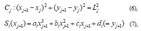 where xj+1 satisfies xi < xj+1 < xi+1. By repeating these procedures, each joint position is derived. Finally, each joint angle is derived by the following formula:
![]()
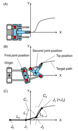 Figure 11: Schematic figure of the definition of the rear links in the FLSAM; (A) state of the arm tip on the ordinate of the global coordinate system, (B) definition of the rear links in FLSAM, (C) definition of each joint coordinate and link length
In this study, using each link length, Lj, and joint angle, θj, as input values, the path-tracing algorithm for the rear links calculates the output value as the number of pulses input to each stepping motor of the sliding screw mechanism. Thus, in the case of the FLSAM, J0=[(x0, y0) = (0, 0)] is the base position, the position of the first joint is J1=[(x1, y1) = (x0 + L0, 0)], the position of the second joint is J2 = [x2, y2], and the position of the arm tip is Jc (= J3) = [x3, y3], since the number of joints is two.
- Simulation of a path-tracing algorithm in the rear links of the FLSAM
Computational simulation was performed to evaluate whether the proposed rear-link path-tracing algorithm works precisely enough to trace the target path (an arbitrary Spline curve). This simulation was done with a custom-designed graphical user interface using LabVIEW 12.0.1. Figure 12 shows the simulation results of the trajectories of the tip and the second joint calculated by using each link length and joint angle output from the path-tracing algorithm. Thus, we confirmed that each joint is moving on the Spline curve completely, and that the path-tracing algorithm of the rear link of the FLSAM is correct.
4.3. Methods
The accuracy of the FLSAM motion was measured using a real-time three-dimensional motion capture system (VENUS3D, Nobby Tech., Ltd.). The conceptual motion pattern for path tracing in the FLSAM is shown in Figure 12, which shows that the initial posture was determined, in which the origin of the global coordinate system of the FLSAM was harmonized with the position of the arm tip. The tip of the end effector traced a predetermined target path, and then the rear links followed the tip motion, as shown in Figure 11B. For each slider of the FLSAM, the maximum moving speed was set to 5 mm/s. In addition, the Li-1 (i=1, 2) was lengthened by a step of 2 mm. Three target paths (a figure “S” pattern, an exponential figure pattern, and a sigmoid curve figure pattern) and three mirrored target paths were defined before the experiment and were started from the origin of the global coordinate system. Each pattern was followed in ten trials. The motion trajectory of the arm tip and the second joint were measured to compare the accuracy of the target paths and the motion of the FLSAM. All experiments were conducted on land.
4.4. Results and Discussion
Figure 13 shows the results of all ten trials of tracing (A) the figure “S” and its mirrored patterns, (B) the exponential figure and its mirrored patterns, and (C) the sigmoid curve figure and its mirrored patterns. Time series of the position of the tip in X and Y axis are shown in Fig. 14. It was observed that all ten path trials are highly reproducible, the tip of the FLSAM traced the target paths, and the tracking results and errors were also symmetrical in mirrored paths. These results confirm the validity of the path-tracing algorithm. The maximum and the root mean square of the deviations were (2.25 mm, 1.7 mm) for pattern (A), (1.86 mm, 0.66 mm) for pattern (B), and (4.7 mm, 1.48 mm) for pattern (C), respectively. All of these deviations were under 4.0% (2.8 mm) of the total width of the FLSAM (140 mm). Although the same tendencies had found in the previous studies (e.g.; series studies of path tracing of a snake-type robot using screw driving theorem by same group [25-26]) that the deviations are approximately 4.0%, it is suggested that the path-tracing algorithm for the FLSAM while path tracing is effective, and minimizing the deviations is a task for future studies. In addition, the movement error of 4% (2.8 mm) is below 4% or less of the survey target size of 90 mm or more. In this respect, the validity of the path-tracing algorithm of the rear links of the FLSAM proposed in this paper was confirmed.
We would like to construct an algorithm to achieve three-dimensional motion by changing the arrangement and the number of sliding screw mechanisms of the FLSAM. Further studies should be needed at least the following points; (1) to improve the accuracy of path tracing, since the tracing deviations would accumulate if the FLSAM would be expanded to increase the number of joints, making it possible for a large error to occur at the tip position and (2) to generate a following path of rear links from the movement path of the tip instead of the Spline curve used in this study.
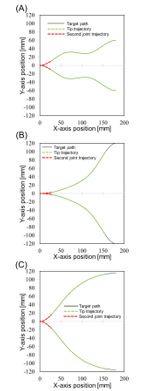 Figure 12: Simulation results of the path tracing algorithm; (A) figure “S” and its mirrored pattern, (B) the exponential figure and its mirrored patterns, and (C) the sigmoid curve figure and its mirrored patterns. Black lines are the target paths, green lines are the tip trajectories, and red lines are the trajectories of the second joint position.
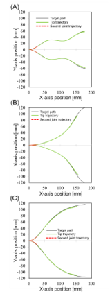 Figure 13: Results of path tracing by the FLSAM; (A) figure “S” and its mirrored pattern, (B) the exponential figure and its mirrored patterns, and (C) the sigmoid curve figure and its mirrored patterns. Black lines are the target paths, green lines are the tip trajectories, and red lines are the trajectories of the second joint position.
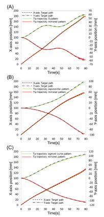 Figure 14: Time series of the position of the tip in X and Y axis; (A) figure “S” and its mirrored pattern, (B) the exponential figure and its mirrored patterns, and (C) the sigmoid curve figure and its mirrored patterns.
5. Conclusion
In order to realize a flexible underwater robot arm, we adopted a sliding screw mechanism and developed a prototype device, a “FLSAM.” Path tracing in the rear-link mechanisms and underwater operation tests were executed, and the results suggested that the sliding screw mechanism is sufficient for construction of a flexible underwater robot arm. However, to obtain stable video data, further modification, such as using an autonomous postural control base, is necessary. Further study is also needed to improve the path-tracing control performance using kinematic and dynamic analysis of the FLSAM.
Appendix-1: Calculation of the cubic Spline interpolation curve
For the target path, a cubic Spline interpolation curve capable of creating a two-dimensional curve in space is used. The nth Spline interpolation is continuous to the (n-1)th derivative function, and oscillations between the representative points hardly occur. In addition, it is effective for generating a target path simulating an obstacle-avoidance route, since it is possible to produce a complicated shape in accordance with the given interpolation points. In this study, a cubic Spline curve was calculated by setting the first interpolation point as the origin of the global coordinate system and sequentially setting the next interpolation point at an arbitrary position in two-dimensional space.
When (n+1) points are given, there are n interpolation divisions, and the polynomials exist in each division as follows:
![]() where Si(x) is the cubic Spline curve function in the ith division; ai, bi, ci, and di are the coefficients in ith division; and i (i=1 to N) equals the number of deviations. The coefficients of the polynomial (ai, bi, ci, and di) are derived using the continuous condition (A2–4) at the interpolation point and the two boundary conditions (A5–6), as follows:
where Si(x) is the cubic Spline curve function in the ith division; ai, bi, ci, and di are the coefficients in ith division; and i (i=1 to N) equals the number of deviations. The coefficients of the polynomial (ai, bi, ci, and di) are derived using the continuous condition (A2–4) at the interpolation point and the two boundary conditions (A5–6), as follows:
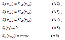 where the ith interpolation point coordinate is taken as (xi, yi), and in this study. In the boundary condition (A5), the first derivatives of the start point of the Spline curve are set to 0, so that the Spline curves of the target path the and X axis are continuous at the origin of the global coordinate system.
Conflict of Interest
The authors declare no conflict of interest.
Acknowledgment
This work was supported by JSPS KAKENHI Grant Number 17K08029.
- Iwamochi?M. Takagi and T. Miyoshi “Flexible Lengthening-Shortening Arm Mechanism for an Underwater Vehicle”, Proceedings of 2017 IEEE International Conference on Mechatronics and Automation? MP1-6(6), 2017. http://doi.org/10.1109/ICMA.2017.8015921
- Pyo. H. Cho, H. Joe, T. Ura and S. Yu, “Development of hovering type AUV “Cyclops” and its performance evaluation using image mosaicking”, Ocean Engineering, vol.109, pp.517-530, 2015. https://doi.org/10.1016/j.oceaneng.2015.09.023
- Kawamura, “Underwater robot development for manipulation task and their uses in Biwa lake”, IFAC-PapersOnLine, vol.48, No.2, pp.14-19, 2015. https://doi.org/10.1016/j.ifacol.2015.06.003
- Gao. B. Zgeng, J. Liang and C. Ren, “Development of an Underwater Robot for Sediment Soil Sampling”, Proceedings of the 3rd International Conference on Mechatronics and Industrial Informatics, pp.6-11, 2015. http://doi.org/10.2991/icmii-15.2015.2
- Satoh, M. Takagi, H. Mori and T. Miyoshi, “Development of an Underwater Robot for Researching of Underwater Environmental”, The Japan Society of Mechanical Engineers, The Proceedings of JSME annual Conference on Robotics and Mechatronics (Robomec), Session ID: 1A2-16b5, 2016. http://doi.org/10.1299/jsmermd.2016.1A2-16b5
- Sakagami, M. Shibata, H. Hashizume and Y. Hagiwara, “Development of a Human-Sized ROV with Dual-Arm”, The proceedings of the Oceans 2010 IEEE, 2010. http://doi.org/10.1109/OCEANSSYD.2010.5603897
- Shim, B.H. Jun, P.M. Lee, H. Beak and J. Lee, “Workspace control system of underwater tele-operated manipulators on an ROV”, Ocean Engineering, vol.37, No.11-12, pp.1036-1047, 2010. https://doi.org/10.1016/j.oceaneng.2010.03.017
- Liljeback, O. Stavdahl, K. Pettersen and J. T. Gravdahl, “A review on modelling, implementation, and control of snake robots”, Robotics and Autonomous Systems, vol.60, No.1, pp.29-40, 2012. https://doi.org/10.1016/j.robot.2011.08.010
- Hirose ans H. Yamada, “Snake-like robots [Tutorial]”, IEEE Robotics & Automation Magazine, vol.16, No.1, pp.88-98, 2010. http://doi.org/10.1109/MRA.2009.932130
- Granosik, J. Borenstein and M. G. Hansen, Serpentine Robots for Industrial Inspection and Surveillance, Industrial Robotics: Programming, Simulation and Applications, 2006. http://doi.org/10.5772/4921
- Stromsoyen, “Propulsion Methods for Under Water Snake Robots – Investigation and Simulation Using Foil for Propulsion of a Snake Robot”, Master thesis, Norwegian University of Science and Technology, 2015.
- Wolf, H. B. Brown, R. Casciola, A. Costa, M. Schwerin, E. Shamas and H. Choset, “A Mobile Hyper Redundant Mechanism for Search and Rescue Tasks”, The proceedings 2003 IEEE/RSJ International Conference on Intelligent Robots and Systems, 2003. http://doi.org/10.1109/IROS.2003.1249309
- Buckingham, V. Chitrakaran, R. Conkie and G. Ferguson et al, “Snake-Arm Robots: A New Approach to Aircraft Assembly”, SAE Technical Paper, 2007-01-3870, 2007. https://doi.org/10.4271/2007-01-3870.
- Palmer, S. C. Guzman and D. Axinte, “Real-time method for tip following navigation of continuum snake arm robots”, Robotics and Autonomous Systems, vol.62, No.10, pp.1478-1485, 2014. https://doi.org/10.1016/j.robot.2014.05.013
- Nakagawa and K. Yoshimura, “Super-multi Joint Manipulator Composed of Linking 3 DOF Joint Unit”, The Japan Society of Mechanical Engineers, The proceedings of the JSME annual meeting, Session ID: 834, May 2005. http://doi.org/10.1299/jsmemecjo.2005.5.0_7
- Hirose and S. Ma, “A moray drive of multi-joint manipulator”, Journal of the Robotics Society of Japan, vol. 8, No.1, pp.9-16, 1990. http://doi.org/10.7210/jrsj.8.9
- Ma, S. Hirose and K. Yokoshima, “2 DOF moray drive for multijoint manipulators”, Journal of the Robotics Society of Japan, vol.14, No.3, pp.436-443, 1996. http://doi.org/10.7210/jrsj.14.436
- Ma and I. Kobayashi, “Path-tracking control of a moray-type robot arm with consideration of actuator’s actuation characteristics”, Journal of the Robotics Society of Japan, vol.18, No.1, pp.135-141, 2000. http://doi.org/10.7210/jrsj.18.135
- Ma and Y. Ohmameuda, “Obstacle avoidance control of moray-type robot arm”, Transactions of the Japan Society of Mechanical Engineers Series C, vol.68, No.670, pp.1791-1797, 2002. http://doi.org/10.1299/kikaic.68.1791
- Cao, V.J. Modi, C.W.de Silva, M. Chen and A.K.Misra, “Trajectory tracking experiments using a novel manipulator”, Acta Astronautica, vol.52, pp.523-540, 2003. https://doi.org/10.1016/S0094-5765(02)00123-6
- Kelasidi, P. Liljeback, K. Y. Pettersen and J. Tommy Gravdahl, “Integral line-of-sight guidance for path following control of underwater snake robots: Theory and Experiments”, IEEE Transactions on Robotics, vol.33, No.3, pp.610-628, 2017. http://doi.org/10.1109/TRO.2017.2651119
- Hara, S. Satomura and F. Matsuno et al, “Development and Test of Fundamental Action of Snake-Like Robot with Driving Mechanism Based on Screw Principle”, The Japan Society of Mechanical Engineers, The Proceedings of JSME annual Conference on Robotics and Mechatronics (Robomec), Session ID: 2P2-D27, 2006. http://doi.org/10.1299/jsmermd.2006._2P2-D27_1
- Kamegawa and F. Matsuno, “Development of a remote-controlled double headed snake-like rescue robot KOHGA”, Journal of the Robotics Society of Japan, vol.25, No.7, pp.1074-1081, 2007. http://doi.org/10.7210/jrsj.25.1074
- Ito, R. Murai and K. Nakamichi, “Development of snake-like rescue robot designed for ease of use ”, Journal of the Robotics Society of Japan, vol.27, No.4, pp.419-426, 2009. http://doi.org/10.7210/jrsj.27.419
- Hara, S. Satomura, H. Fukushima, T. Kamegawa, H. Igarashi and F. Matsuno, “Control of a Snake-like Robot Using the Screw Drive Mechanism”, Proceedings of 2007 IEEE International Conference on Robotics and Automation, Roma Italy, 2007. http://doi.org/10.1109/ROBOT.2007.364074
- Fukushima, M. Tanaka, T. Kamegawa and F. Matsuno, “Front-Unit-Following Control of a Snake-like Robot Using Screw Drive Mechanism”, Journal of the Robotics Society of Japan, vol.28, No.6, pp.707-714, 2010. http://doi.org/10.7210/jrsj.28.707