Cyclical Wave Bolt for Sound Waves in a Gas Stream

Adv. Sci. Technol. Eng. Syst. J. 2(6), 272–274 (2017);
 DOI: 10.25046/aj020633
This article is devoted to the problem of blocking the propagation of sound in a gas stream. This can be useful in the problems of pipeline acoustics and the design of automotive silencers, when it is necessary to ensure the opacity of the boundary (cross section of the pipe) for sound simultaneously with the free (ideally) flow through this boundary. The tool for solving this problem is the rapid periodic overlapping of waveguide (gas-conducting) channels in a system of parallel waveguides. The design of the proposed device assumes the following technological requirements: high mechanical rigidity of the elements, high accuracy of their manufacture and high rotor speed. Fulfillment of these conditions allows creating an effective device for blocking sound in the gas flow. Such a device may have small wave dimensions (with respect to the wavelength of sound) and a small expenditure of mechanical power to push gas through it very wide frequency range of silencing.
1. Introduction
In practice, sometimes it is necessary to place a filter in the path of the gas flow (with velocity v) in the pipe (and simultaneously sound with speed с in the tube as an acoustic waveguide). This filter must pass the flow of gas and block sound waves on its output. Such situations are encountered in problems of the acoustics of pipelines and also in the problem of designing exhaust silencers for cars with internal combustion engines. Next we will call such a device a silencer. The area of the inlet and outlet cross-section of the silencer is assumed equal , the average velocity of the flow at the inlet and outlet of the silencer is (see Figure 1). The time-average gas pressures at Q the outlet and inlet of the silencer are, respectively, and , where . The quality of the silencers is characterized by the following parameters:
(a) the degree
![]() of sound pressure suppression (of course preferably );
of sound pressure suppression (of course preferably );
(b) the frequency range
![]() of sound suppression, preferably when
of sound suppression, preferably when
![]() (c) the wave dimensions
(c) the wave dimensions
![]() of the device (where is the geometric size of the silencer, -is a sound speed, preferably when );
of the device (where is the geometric size of the silencer, -is a sound speed, preferably when );
![]() (d) the relative loss of power to propel the gas through the silencer ( – gas mass density, preferably when ). For a silencer, this condition is necessary
(d) the relative loss of power to propel the gas through the silencer ( – gas mass density, preferably when ). For a silencer, this condition is necessary
![]() Always this combination is desirable (in addition to (1))
Always this combination is desirable (in addition to (1))
![]() Violation of the conditions (7) (or one of these conditions) is usually (for systems with parameters that are constant in time) a payment for the fulfillment of the condition (6). Widely known are the following three approaches [1] in the design of such devices: when narrow-band ( ) absorption is permissible and one can be satisfied with resonant absorption of active suppression of sound; when large silencer dimensions are permissible ( ) and one can be satisfied by a Helmholtz resonator with a resonant frequency below the minimum sound frequency in the flow at low energy costs to propel the gas; when the high energy expenditure for pushing the gas through a classical rigid plate, perforated with small holes ( ).
Violation of the conditions (7) (or one of these conditions) is usually (for systems with parameters that are constant in time) a payment for the fulfillment of the condition (6). Widely known are the following three approaches [1] in the design of such devices: when narrow-band ( ) absorption is permissible and one can be satisfied with resonant absorption of active suppression of sound; when large silencer dimensions are permissible ( ) and one can be satisfied by a Helmholtz resonator with a resonant frequency below the minimum sound frequency in the flow at low energy costs to propel the gas; when the high energy expenditure for pushing the gas through a classical rigid plate, perforated with small holes ( ).
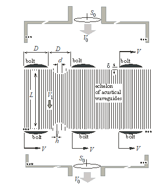 Figure 1. Two-dimensional version of cyclical wave bolt
2.Cyclical Wave Bolt
The above solutions [1] for blocking sound in a stream (with or without sound absorption) were based on systems with time-constant parameters. We now consider a system with parameters modulated in time [2]. We consider the infinite echelon (see Figure 1) of waveguides with rigid vertical plane walls, located at a characteristic distance from each other, where is characteristic thickness of walls. Two horizontal systems of rigid thin bands (wave bolts) of the width , separated from each other by the distance move horizontally (to the right) with the velocity near the upper and lower edges of the echelon of above mentioned waveguides of length . A sound wave is incident on top of this system and an excessive pressure is applied to push the gas flow through this system. The gap between bolts and ends of waveguides is limited by condition . We call such a parametric structure a cyclical wave bolt (CWB). From above, a sound wave falls on the echelon of waveguides, periodically blocked by wave bolts. If the conditions
![]()
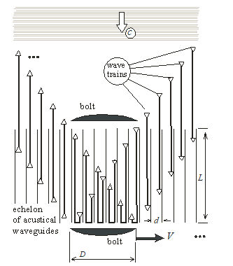 Figure 2. Space diagram of seven incoming wave trains, moving inside the echelon of waveguide channels
of synchronism are satisfied, the incident wave either reflects upward from the upper running bolts, or from the lower ones (Figure 2). Due to condition (10), each waveguide is open at both ends for a certain period of time and is closed by wave bolts at both ends during a subsequent time interval of the same duration . During the first interval (with open bolts), the sound wave fills this waveguide, during the subsequent interval (with closed bolts), the wave turns completely to reverse motion (due to full reflection from closed wave bolts). Thus, any perturbation propagating in a gas at a speed cannot overcome CWB. On the other hand, for a gas flow this system is transparent. The only limitation of its transparency for the flow is the friction of the gas against the walls of the waveguides, which leads to additional energy loss. Waves, reflected not from the bolts, but from the open ends of the waveguides, do not leave the CWB. In principle, the operation of the system will be the same if the bolts are made stationary, and the train vertical walls is made to move at speed .
3. Three-Dimensional Version of Cyclical Wave Bolt
Figure 3 shows a three dimensional cylindrical analogue (axially symmetric device) of the infinite two dimensional system described above.
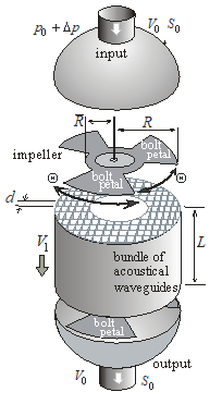 Figure 3. Three-dimensional version of silencer.
An infinite spatially periodic two dimensional bolt system is replaced by rotating (with angular frequency ) acoustically rigid (for sound in gas) impeller or rotary switch with petals (bolts) with angular sectors of the petals and the same angular sector between adjacent petals. Both ends of each waveguide of length with a characteristic transverse dimension (with rigid walls of thickness ) are open during time intervals and are closed at intervals of time by bolts (or petals of rotating impeller), where is a certain initial moment, determined by the point of placement of this waveguide and the phase of rotation of the impeller, where
![]() The relation (11) is analog of synchronism condition (10). A bundle of tubes (waveguides) is located between the radii and . Any wave train that gets into the waveguide of length in time has time to fully rotate to exit this waveguide. The maximum rigidity of structural elements and the maximum rotor speed are determined by modern state of technology level. We note that the gas velocity inside the waveguide tubes must ensure that the Mach number is small, i.e. . By decreasing the value we simultaneously reduce the Mach number inside the waveguides and the relative power loss . The rotor of the impeller is driven by an electric motor with a stabilized rotational frequency . The frequency of incident waves in the flow is bounded from above only by the condition of one dimensionality of sound propagation in the rigid tube, i.e. its characteristic transverse scale , i.e. . Minimum cross-sectional dimension of the tubes is limited below by the condition of a fairly low energy expenses to push gas trough the waveguides. The maximum cross-sectional dimension of the tubes is bounded above by the condition . That the switching time of one tube is small compared with the propagation time of sound along the tube. Minimal length of the tubes-waveguides is limited from below by the maximum achievable frequency of the rotation of impeller. The minimum gap between the impeller (wave bolts, petals) and the ends of the tubes is limited from below by the manufacturing accuracy and stiffness.
The relation (11) is analog of synchronism condition (10). A bundle of tubes (waveguides) is located between the radii and . Any wave train that gets into the waveguide of length in time has time to fully rotate to exit this waveguide. The maximum rigidity of structural elements and the maximum rotor speed are determined by modern state of technology level. We note that the gas velocity inside the waveguide tubes must ensure that the Mach number is small, i.e. . By decreasing the value we simultaneously reduce the Mach number inside the waveguides and the relative power loss . The rotor of the impeller is driven by an electric motor with a stabilized rotational frequency . The frequency of incident waves in the flow is bounded from above only by the condition of one dimensionality of sound propagation in the rigid tube, i.e. its characteristic transverse scale , i.e. . Minimum cross-sectional dimension of the tubes is limited below by the condition of a fairly low energy expenses to push gas trough the waveguides. The maximum cross-sectional dimension of the tubes is bounded above by the condition . That the switching time of one tube is small compared with the propagation time of sound along the tube. Minimal length of the tubes-waveguides is limited from below by the maximum achievable frequency of the rotation of impeller. The minimum gap between the impeller (wave bolts, petals) and the ends of the tubes is limited from below by the manufacturing accuracy and stiffness.
Conclusions
Silencer considered can provide a low level of sound at the output, less engine power loss, a wider bands of sound suppression at smaller wave dimensions or, in other words, joint fulfillment of conditions (6), (7). The loss of power to push gas through acoustic waveguides can be reduced by shortening and by increasing the rotational speed of the impeller (until too much power is required to rotate it). The input and output of device can be interchanged, it acts symmetrically: it does not pass through itself the perturbation propagating in gas at the speed of sound.
- Fuchs, Applied Acoustics: Concepts, Absorbers, and Silencers for Acoustical Comfort and Noise Control: Alternative Solutions – Innovative Tools – Practical Examples, Springer Science & Business Media, 2013.
- Arabadzhi, Solutions to Problems of Controlling Long Waves with the Help of Micro-Structure Tools, Bentham Science Publishers Ltd., 2011.