2×1 Microstrip Patch Array Antenna with Harmonic Suppression Capability for Rectenna

Adv. Sci. Technol. Eng. Syst. J. 2(6), 267–271 (2017);
 DOI: 10.25046/aj020632
This paper is an extension of work originally presented in 2016 IEEE Asia-Pacific Conference on Applied Electromagnetics (APACE). A 2×1 microstrip patch array antenna integrated with photonic bandgap (PBG) and stubs is designed and analyzed. The performance of the PBG and stubs structure are explained and analyzed in terms of the elimination of the resonance at the harmonic frequencies of the antenna. The proposed antenna is designed on FR-4 substrate with thickness of 1.6 mm and operated at 2.45 GHz frequency suitable for rectenna design application. From the simulated result, the first harmonic frequency (5.4 GHz), the second harmonic frequency (6.6 GHz) and the third harmonic frequency (7.8 GHz) are successfully suppressed. For instance, the radiation to the forward of the stubs-PBG antenna is suppressed at more than 15 dB at the second and third harmonic frequencies.
1. Introduction
The term rectenna is commonly denoted as rectifying antenna at microwave power transmission system. It is a combination of the antenna and high efficient rectifier circuit. The ability of the wireless power transmission system is very important and it depends on the ability of each process; the conversion of signal DC-to-RF at the transmitter, at the transmission and at the conversion of signal RF-to-DC at the receiver. Hence, the receiving antenna is one of the main elements in the rectenna system development.
One of the most popular types of receiving antenna that is used for rectenna application is the microstrip patch antenna [1 – 4]. Some of the advantages of employing this type of antenna is low profile, low cost, light-weight and suitable if integrated with RF devices. However, it also exhibits disadvantages such as the excitation of surface waves that exist in the substrate layer. Surface waves are exceptionable because when a patch antenna radiates, a part of the total available radiated power becomes trapped along the surface of the substrate. It will diminish the total available power for radiation to space wave, and the harmonic frequency is produced. In addition, for arrays antenna, surface waves have a significant impact on the mutual coupling between array elements [5]. Moreover, in rectifying circuit, diode that used to convert the RF signal to DC power supply also generates the unwanted radiation of harmonic frequencies. Thus, the rectenna cannot operate well and will disturb the overall performance of the system.
Several design methods have been proposed in the past in order to overcome these unwanted generated harmonic problems. One of the most popular methods is called the photonic band gap (PBG) or electromagnetic band gap (EBG) [6 – 8] and defected ground structure (DGS) [9 – 11]. Several other techniques for instance antenna with slit and stub structure [12], circular sector patch antenna [13], slot antenna and notch antenna [14], Low Pass Filter (LPF) [15 – 17] also have been discussed earlier as a one of the method to suppress the harmonic frequencies.
According to that, a harmonic suppression microstrip array patch antenna is proposed in order to improve the system performance. In this paper, the 2×1 microstrip patch array antenna integrated with stubs and two-dimensional (2-D) PBG pattern in the ground plane beneath the square patch, is proved experimentally and the capability of the stubs and PBG structure for the suppression of the harmonics are discussed [18].
2. Antenna design procedure
2.1. Numerical method
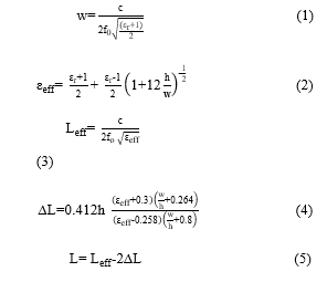
The structure of the microstrip patch array antenna with PBG substrate (PBG antenna) is presented in Figure 2. A 2×1 array antenna is fabricated on the FR-4 substrate with dimensions of 143 x 52 x 1.6 mm3 and the relative permittivity of Ԑr = 4.4. The source signal is fed directly to the antenna by the 50Ω microstrip line with width length (Wd2) = 4.13 mm. The rectangular inset feed antenna dimensions are calculated prior to designing the array antenna by using [19]:
 Where:
W = Width of the patch
L = Length of the patch
Ԑr = Dielectric constant of substrate
Ԑreff = Effective dielectric constant of substrate
c = Speed of light
f0 = Frequency reference
h = Height of dielectric substrate
There are advantages of PBG structure which are increasing the antenna’s performance in terms of the gain and radiation pattern and also react as a filter to suppress the harmonic frequency. The PBG structure is designed based on the formula [20]:
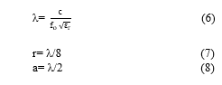 After calculation, the 9 x 5 squares with the dimensions 7 x 7 mm2 are etched in the ground plane at the period (gb) of 15 mm as shown in Figure 1.
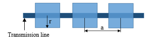 Figure 1: PBG structure at ground plane
2.2. Design simulation
By using CST microwave software, the rectangular inset feed antenna is designed and simulated to get the operating frequency at 2.45 GHz. Some enhancement are made to obtain the best performance of the antenna. After completing the single element geometry, a 2×1 array antenna is designed. The parameters of the feed line network can be chosen by setting the feed line impedance to 50 Ω (Z1 = 50 Ω), which splits into two 100 Ω (Z2 = 100 Ω) [21]. Similarly, some optimization is done in order to get the greatest achievement of the array antenna.
After done with the conventional microstrip patch array antenna design, the 9 x 5 PBG square are etched at the ground plane. However, some size optimization of PBG square size is done in order to match with the 2×1 array patch antenna design.
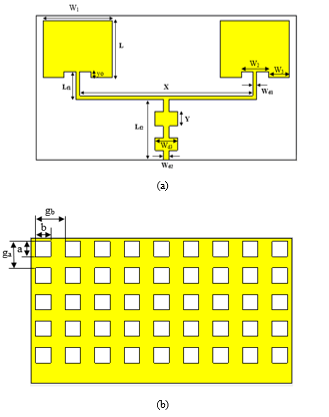 Figure 2: 2×1 microstrip patch array antenna with stubs and PBG structure
(a) view from the front (b) view from the back.
Table 1: Dimension of antenna (unit: mm)
| Parameter | Dimension | Parameter | Dimension |
| L | 29.16 | Wd3 | 11.3 |
| W1 | 37.61 | X | 88.32 |
| W2 | 10 | Y | 5 |
| W3 | 13.805 | a | 7 |
| Lf1 | 5.5 | b | 7 |
| Lf2 | 15.7 | ga | 15 |
| Wd1 | 0.71 | g | 15 |
| Wd2 | 4.13 |
3. Result and discussion
This proposed antenna is divided into three parts which are normal array patch antenna, PBG array antenna and array patch antenna with PBG and stub structure. Each part is discussed and analyzed according to their characteristics.
3.1. Normal array patch antenna
The normal patch antenna without PBG structure shows in Figure 3 is simulated and measured for the comparison of the basic characteristics. The resonant frequency of the fundamental is adjusted to be 2.45 GHz for the antenna. The simulated and measured S-parameter (return loss) result of the array antenna without stubs and PBG structures are shown in Figure 4. As can see, the return loss is at -13 dB and has a few harmonic frequencies which are not good for an antenna.
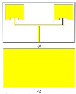 Figure 3: 2×1 rectangular inset feed array antenna (a) front view (b) back view
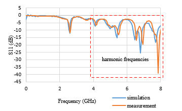 Figure 4: Simulated and measured result for S-parameter (return loss) of 2×1 rectangular inset feed array antenna
3.2. PBG structure
As can see in Figure 4, there are a lots of harmonic frequencies produces above 4 GHz. Hence, PBG structure is beneath at the ground in order to suppress the harmonic frequencies. At the same time, the gain of the antenna also can be improved. Figure 5 shows the PBG structure at ground plane. This arrangement of the PBG lattice produces the band pass characteristics of the transmission parameter at more than -20 dB from 4.6 GHz to 8 GHz shown in Figure 6 (a) when the uniform microstrip line is fabricated on this substrate instead of the patch antenna. The effect of the PBG can be seen by observing the S-parameter (return loss) in Figure 6 (b). It shows that the harmonic frequencies above 4.6 GHz is successfully suppressed when the S-parameter of PBG structure is compare with return loss of 2×1 rectangular inset feed array antenna with and without PBG structure. While Figure 7 shows the comparison of return loss of 2×1 rectangular inset feed array antenna with PBG structure only between simulation and measurement.
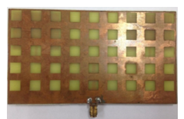 Figure 5: Prototype of PBG structure at ground plane
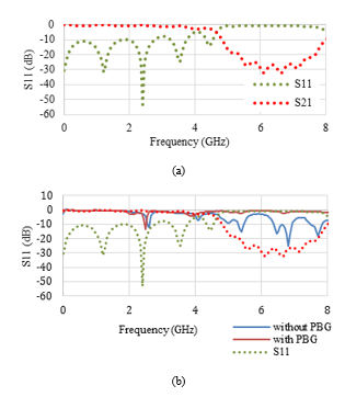 Figure 6: The effect of PBG structure (a) S-parameter of PBG square structure (b) comparison S-parameter of PBG square with return loss of 2×1 rectangular inset feed array antenna with and without PBG structure
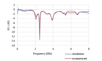 Figure 7: Simulated and measured result for return loss of 2×1 rectangular inset feed array antenna with PBG structure only
3.3. Array patch antenna with PBG and stub structure
The final design is combination of normal array patch antenna with PBG and stubs structure as shown is Figure 8. The S-parameter (return loss) of the array antenna with PBG and stubs structure, and the array antenna without PBG and stubs structure are shown in Figure 9.
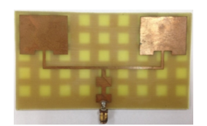 Figure 8: Prototype of 2×1 rectangular inset feed array antenna with PBG structure and stub
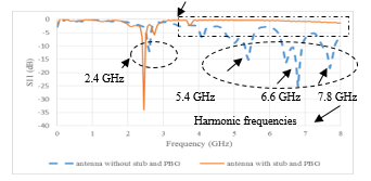 Figure 9: Measured S-Parameter (return loss) of the proposed array antenna. Graph of the comparison for antenna with and without stubs and PBG
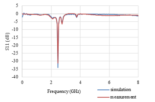 Figure 10: Comparison of return loss between simulation and measurement for 2×1 array patch antenna with PBG and stub structure
Figure 9 shows, a comparison between conventional array antenna with array antenna with PBG and stubs structure indicates that the harmonic frequencies are indeed suppressed. According to the theoretical design, the return loss is observed at 2.45 GHz. However from measurement result, the S-Parameter (return loss) is observed at 2.6 GHz for conventional antenna while for stubs-PBG antenna is at 2.45 GHz. Through observation, the antenna performances are increased. The return loss is revised from -12.05 dB to -34.99 dB after the stub and PBG is added. Besides, based on to the characteristic of PBG, it also can suppress the surface wave in the band-gap. A periodic structure surrounding the patches in addition to one underneath the patches is essential for effective suppression of the harmonic and surface wave. Figure 10 depicts the comparison between simulated and measured return loss of the proposed array antenna.
3.4. Gain
As mentioned before, besides suppressing the harmonic frequency, PBG structure also can increase the performance of the antenna in terms of gain. As can be seen in Figure 11 (a) and (b), there are comparison antenna’s gain between simulation and measurement for normal array patch antenna and PBG array patch antenna.
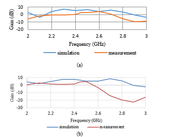 Figure 11: Comparison of antenna’s gain between simulation and measurement (a) normal array patch antenna (b) PBG array patch antenna
Figure 11 (a) shows the gain comparison between simulation and measurement for normal array patch antenna. From the graph, the gain for 2.45 GHz is 6.263 dB for simulation while 3.15 dB for measurement. The gain increases to 6.436 dB when the PBG structure is added as shows in Figure 11 (b). While for measurement, the gain is 4.31 dB.
In Table 2, due to the effective suppression of the harmonic and the surface wave, and changes in the current distribution, the antenna array with stub and PBG has higher gain compared to the normal array antenna. The gain increase about 82.41% which is from 3.156 dB to 5.757 dB. While for normal array antenna and array antenna with PBG structure, the result shows a minimal gain increase by 36.66%. Thus, it shows that with the addition of stub structure at the feed line, the gain’s performance will improve more. Moreover, the mixed current distribution is useful for diminishing the mutual coupling between the patches and decreasing the maximum side-lobe level.
Table 2: Measured antenna gain base on structure added
| Antenna structure | Gain (dB) |
| Array antenna without PBG and stub | 3.156 |
| Array antenna with PBG | 4.313 |
| Array antenna with PBG and stub | 5.757 |
4. Conclusion
2×1 microstrip patch array antenna has been presented in this effort. The proposed structure is integrated with two-dimensional PBG pattern in the ground plane under the square patch and stubs. The effectiveness of the PBG and stubs structure for harmonic suppression are analyzed. The simulation and measurement works verified that the combination of the array antenna with PBG and stubs is efficient in eliminating unwanted frequencies. Moreover, the performances of the antenna in term of gain also increase.
Acknowledgment
The authors would like to thank the Centre Graduate Study UTHM for supporting this study. Much appreciation also goes to the Electromagnetic Compability Lab (EMC Centre), Universiti Tun Hussein Onn Malaysia for providing the measurement facilities.
- A. Vera, A. Georgiadis, A. Collado, and S. Via, “Design of a 2.45 GHz rectenna for electromagnetic (EM) energy scavenging,” Radio and Wireless Symposium (RWS), 2010 IEEE(pp. 61-64). IEEE, 2010.
- Olgun, C. C. Chen and J. L. Volakis, “Wireless power harvesting with planar rectennas for 2.45 GHz RFIDs,”Electromagnetic Theory (EMTS), 2010 URSI International Symposium on(pp. 329-331). IEEE, 2010
- Takhedmit, B. Merabet, L. Cirio, B. Allard, F. Costa, C. Vollaire and O. Picon, “A 2.45-GHz low cost and efficient rectenna,” Antennas and Propagation (EuCAP), 2010 Proceedings of the Fourth European Conference on(pp. 1-5). IEEE, 2010
- Zhang, Y. Huang and P. Cao, “Harvesting RF energy with rectenna arrays,” Antennas and Propagation (EUCAP), 2012 6th European Conference on(pp. 365-367). IEEE, 2012
- M. Nashaat Elsheakh, M. F. Iskander, E. A.-F. Abdallah, H. A. Elsadek, and H. Elhenawy, “Microstrip Array Antenna with New 2D-Electromagnetic Band Gap Structure Shapes to Reduce Harmonics and Mutual Coupling,” Prog. Electromagn. Res. C, vol. 12, pp. 203–213, 2010. http://onlinewww.jpier.org/PIERC/pierc12/17.09112008.pdf
- N. Aktar, M. S. Uddin, M. R. Amin, and M. A. Ali, “Enhanced gain and bandwidth of patch antenna using ebg substrates,” Int. J. Wirel. Mob. Networks, vol. 3, 2011. https://www.researchgate.net/profile/Mst_Nargis_Aktar/publication/4996598 5_Enhanced_Gain_and_Bandwidth_of_Patch_Antenna_Using_EBG_Substra tes/links/0912f50973187d409b000000.pdf
- Horii and M. Tsutsumi, “Harmonic control by photonic bandgap on microstrip patch antenna,” Microwave and Guided Wave Letters, IEEE, 9(1), 13-15, 1999
- Zhang, J. Mao, X. Sun, R. Qian, and D. Zhang, “Microstrip patch antenna array on ground with circular PBG,” Microwave and optical technology letters, 41(2), 127-130, 2004.
- S. Kushwah and G. S. Tomar, “Size reduction of microstrip patch antenna using Defected Microstrip Structures,” Proc. – 2011 Int. Conf. Commun. Syst. Netw. Technol. CSNT 2011, pp. 203–207, 2011.
- Dua, H. Singh, and N. Gambhir, “2.45 GHz Microstrip Patch Antenna with Defected Ground Structure for Bluetooth,” … J. Soft Comput. Eng. …, no. 6, pp. 262–265, 2012. http://citeseerx.ist.psu.edu/viewdoc/download?doi=10.1.1.473.2510&rep=rep 1&type=pdf
- S. Ghaffarian, G. Moradi, and R. Zaker, “Harmonic suppression slot antenna using rectangular defected ground structure,” Electrical Engineering (ICEE), 2011 19th Iranian Conference on (pp. 1-4). IEEE, 2011.
- A. Rahim, F. Malek, S. F. W. Anwar, S. L. S. Hassan, M. N. Junita, and H. F. Hassan, “A harmonic suppression circularly polarized patch antenna for an RF ambient energy harvesting system,” CEAT 2013 – 2013 IEEE Conf. Clean Energy Technol., pp. 33–37, 2013.
- J. Huang, T. C. Yo, C. M. Lee, and C. H. Luo, “Design of circular polarization antenna with harmonic suppression for rectenna application,” IEEE Antennas Wirel. Propag. Lett., vol. 11, pp. 592–595, 2012.
- A. Rahim, M. N. Junita, S. I. S. Hassan, and H. F. Hassan, “Harmonics suppression circular polarization elliptical shape microstrip patch antenna,” Proc. 2014 2nd Int. Conf. Technol. Informatics, Manag. Eng. Environ. TIMEE 2014, pp. 147–150, 2015.
- Han, S. Jung and H. Sohn, “High efficient rectenna using a harmonic rejection low pass filter for RF based wireless power transmission,” Wireless Communications Systems (ISWCS), 2014 11th International Symposium on (pp. 423-426). IEEE, 2014.
- Gangwar and R. L. Yadava, “Design and analysis of a pentagonal rectenna,” Signal Processing and Integrated Networks (SPIN), 2014 International Conference on (pp. 654-658). IEEE, 2014.
- Zhang, Y. Huang and P. Cao, “A wideband cross dipole rectenna for RF wireless harvesting,” Antennas and Propagation (EuCAP), 2013 7th European Conference on (pp. 3063-3067). IEEE, 2013.
- A. Amir, S. A. Hamzah, K. N. Ramli, and M. Esa, “2× 1 microstrip patch array antenna with harmonic suppression capability” Applied Electromagnetics (APACE), 2016 IEEE Asia-Pacific Conference on(pp. 272- 276). IEEE, 2016.
- Joshua, M.S, Mayank, M, Prafull, and S, “Design and Optimization of Microstrip Patch Antenna,” Int. J. Emerg. Trends Technol. Comput. Sci., 2013.
- Garde, M. J. Yábar, and C. Del Río, “Simple modeling of DGS to design 1D-PBG low-pass filters,” Microw. Opt. Technol. Lett., vol. 37, no. 3, pp. 228–232, 2003. http://onlinelibrary.wiley.com/doi/10.1002/mop.10878/full
- S. H. Khraisat, “Design of 4 elements rectangular microstrip patch antenna with high gain for 2.4 GHz applications,” Mod. Appl. Sci., vol. 6, no. 1, pp. 68–74, 2012.http://ccsenet.org/journal/index.php/mas/article/view/12540/9541
No related articles were found.