Enhancement of Voltage Stability through Optimal Location of UPFC

Adv. Sci. Technol. Eng. Syst. J. 2(6), 261–266 (2017);
 DOI: 10.25046/aj020631
This paper proposed the identification of the proper placement of UPFC (Unified Power Flow Controller) using a series of methodological numeric simulations to improve voltage stability. For this purpose, the critical zone of the system is determined, then, comparative analyses depending on different emplacements of UPFC are performed. The dynamic model of UPFC and the proposed method are tested on the IEEE 14-bus system. The finding shows that the proper location of UPFC helps in improving voltage profiles and increasing the maximum loading capacity.
1. Introduction
Power systems have been forced to operate close to their stability limits and around their full capacities. This is due to the economic and environmental pressures imposed on the power generation and the construction of new transmission lines [1-4]. On the other hand, the amount of power transmitted across transmission lines is limited for safety and stability considerations. The system is prone to be collapsed when the power flowing exceeds the limits in case of an arbitrary incident [5]. System planners are so more and more focusing on how to manage the obstacles facing the power transmission.
Over the last decades, FACTS (Flexible AC Transmission Systems) devices have opened new perspectives for managing the transmission of the power [6]. Different types of FACTS controllers are available for this aim, but the most powerful and prominent one is UPFC. UPFC is able to control the three parameters of the transmission system: phase angle, impedance, and voltage. In addition, it provides voltage support, improves transient stability and amortizes oscillations [7, 8].
However, according to references [9, 10], the major disadvantage of UPFC is the expensive cost of installation and reactive power generation which is due to the great efforts of its voltage source converters. Therefore, an optimal location of the device helps in achieving good performances and enhancing power system stability with a reduced investment cost [11].
Previous studies have been focused on the optimal placement of UPFC and the evaluation of its impact on system stability using various methods and techniques [12-14]. The authors in reference [15] presented an evolutionary algorithm-based approach to identify the optimal placement and settings of the hybrid device. Reference [16] has investigated the use of UPFC to increase the load ability margin and improve the system stability. The emplacement of the FACTS is decided by the stability indices which determine the critical line, the appropriate line for introducing UPFC. In reference [17], H. Wang investigated the impact of UPFC on the stability of a multi-machine power system. A. Ray et al. [18] studied the application of UPFC for controlling power flow in the transmission line and improving the voltage profile. They computed the VSI (Voltage Stability Index) for each line to integrate UPFC into the line which has got the highest VSI value. In reference [19], authors opted for the CPF (Continuation Power Flow) and LSI (Line Stability Index) for the identification of the suitable location of UPFC. Through simulation results, it was demonstrated that optimal placement of the hybrid FACTS improves the static and transient stability of power system when subjected to large disturbances. S. Lee et al. [20] addressed the determination of UPFC location and rating for voltage stability improvement using the analysis of the Jacobian matrix. Intelligent techniques were applied in reference [21] for the optimal position of UPFC along with series FACTS to minimize the operation cost of the power system. In [22], authors proposed two evolutionary optimization techniques to optimally place and size the hybrid controller in view of reducing the active power losses.
This paper is an extension of work initially published in the Proceedings of the International Conference on Control Engineering &Information Technology [23]. In this work, we proceed with an efficient method for the identification of the proper placement of UPFC, for the purpose of improving voltage stability. We plan a series of methodological dynamic simulations to find the critical zone of IEEE 14-bus case study. The zone having the lowest voltage magnitudes is taken as the best location of UPFC. Then, we perform comparative studies to justify the placement selected. The dynamic model of UPFC and the numerical simulation method are implemented within the software EUROSTAG.
2. Necessity of FACTS devices
Consider a single machine infinite bus system interconnected through a transmission line having reactance , as shown in Figure 1. The power transferred across the transmission line is given in equation (1) [24, 25].
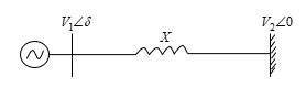 Figure 1. Single machine infinite bus system
![]()
and are the voltages of the synchronous generator and the infinite bus respectively where: and .
The power variation is a sinusoidal function of the difference between the two voltage angles as shown in Figure 2. The maximum power that can be transmitted across the line corresponds to and by considering = = , it is given by:![]()
depends on the value of the reactance which imposes the theoretical limit of the steady state transmitted power. However, the line resistance creates power losses quantified by and thus sets the practical limit of the line. The physical characteristics of the conductor could also limit the power transmission, which is known as the thermal limit.
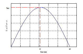 Figure 2. Power-angle curve
From equation (1), we note that the power can be controlled by two parameters; it can be enhanced by increasing the voltage magnitude of the synchronous machine and the infinite bus or by increasing the angular difference of the voltages. However, there are limits imposed on either the voltage magnitude or the angular difference, which have to be considered. The voltage variation must not exceed % of the nominal voltage while the difference between the angles is limited to less than to maintain the transient stability [26, 27].
Therefore, it is inferred that the power transmission is limited by:
- Thermal limitations.
- Physical limitations.
It is possible to deal with the thermal limitations by renovating the transmission lines and opting for a higher current rating conductor. Nonetheless, this solution does not necessarily guarantee voltage within the acceptable boundaries or the flow and the controllability of the power, but it is feasible by line compensation. Electro-mechanical devices used for line compensation cannot achieve rapid compensation and are prone to the wear quicker than the static equipments. The solid-state based technology, FACTS, provides the control of one or more parameters to magnify the loading capability and to develop controllability. As the current in a transmission line has the property to be controlled, it is possible to use a FACTS device for flowing power across the line during normal or disturbed conditions. This returns to the ability of FACTS devices to control all power flow parameters, namely phase angle, bus voltage and line impedance. In other words, the FACTS technology gives the possibility to maintain acceptable voltage magnitude and power flow.
3. UPFC
The UPFC is a hybrid device consisting of two voltage source converters interconnected through a common DC link capacitor, as shown in Figure 3 [28-30]. The inverter 1 is connected in shunt with the transmission line while the inverter 2 is series connected. It injects a series connected. It injects a series voltage controllable in phase and magnitude. The decomposition of this voltage leads to a quadrature component responsible for controlling the real power and an in-phase component which controls the reactive power in the line. Similarly, the injected shunt voltage is decomposed into two components. The quadrature component regulates the voltage of the DC link as for the in-phase component; it controls the exchange of the reactive power with the system.
The model of UPFC is represented in Figure 4 [30, 31]. From this scheme, we can extract the active and reactive power flows of the series and shunt converters which are expressed by the equations (3) – (6).
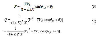
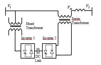 Figure 3. UPFC incorporated in a power system
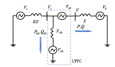 Figure 4. Model of UPFC
Where:
Similarly, the active and reactive powers of the shunt inverter are expressed by:
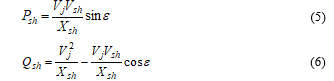 Where: and
KX: Short circuit level;
: Gaussian function
: Relative quadrature series voltage;
: Relative in-phase series voltage;
: Relative quadrature shunt voltage;
: Relative in-phase shunt voltage;
: Right YPFC voltage;
: Series voltage;
: Shunt voltage;
: Real power;
: Reactive power;
: Shunt real power;
: Shunt reactive power.
The modeling of the UPFC shunt part on EUROSTAG is simple; it is represented by a current injector. As for the modeling of the series part, we must open the line where we want to insert UPFC and place at its extremities two current injectors (Figure 5). The opening of the line is assured by a high reactance value.
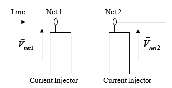 Figure 5. Model of UPFC in EUROSTAG
4. Simulation
4.1. Case Study
To test the proposed method, we used the IEEE 14-bus test system. This system contains two generators each one is equipped with voltage and speed regulators and three synchronous compensators to produce reactive power. It also has two transformers with two windings, a three-winding transformer, fifteen transmission lines and eleven loads. The data of the above mentioned system are taken from reference [31].
EUROSTAG [32] adopts the model considering the voltage behind transient reactance for representing all the generators and constant impedance to model loads and transformers.
4.2. Simulations Results
4.2.1. Identification of the Critical Zone:
The IEEE 14-bus network can be decomposed into a transmission system (69 KV) referred by « zone A » and a distribution one (13.8 KV) referred by « zone B » interconnected through three step-down transformers. To identify the critical zone, we proceeded by an incremental load increase of each zone separately. The part of the network experiencing voltage collapse rapidly is considered as the critical zone.
According to the steady state, we noted that bus 14 is the most insecure bus; it has got the lowest magnitude compared to the other buses. For this reason, we choose to adopt this bus as an index for voltage stability assessment.
Figure 6 shows the main results of increasing load. In zone A, the voltage of bus 14 underwent a progressive decrease of 0.002pu from one case to another until collapsing in the case of 49%. As for zone B, it could not withstand over than 39% of load increase where bus 14 has got the limit voltage amplitude. While the increase of the total system load leads to a severe voltage drop which ends with a collapse when reaching 25%.
Noteworthy that distribution system is the critical zone. All thanks to voltage and speed regulators of synchronous machines which reinforce transmission system stability.
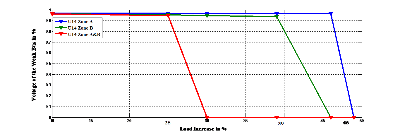 Figure 6. Identification of the critical zone of IEEE 14-Bus system.
4.2.2. UPFC Application:
Having identified the critical zone, we placed UPFC between buses 9 and 14, sized at 60MVAR for each one of its converters. Line 9-14 is close to the weakest bus so that we expect satisfying results when introducing UPFC into it. To evaluate the contribution of the controller, we rerun the system under 20 % of load increase at time t=250s.
As we can see in Figure 7, UPFC was able to considerably increase bus14 voltage amplitude just after perturbation and with well-damped oscillations compared to the uncompensated system. This result indicates the voltage support supplied by the UPFC. Note that we obtained similar results for the other buses of the network.
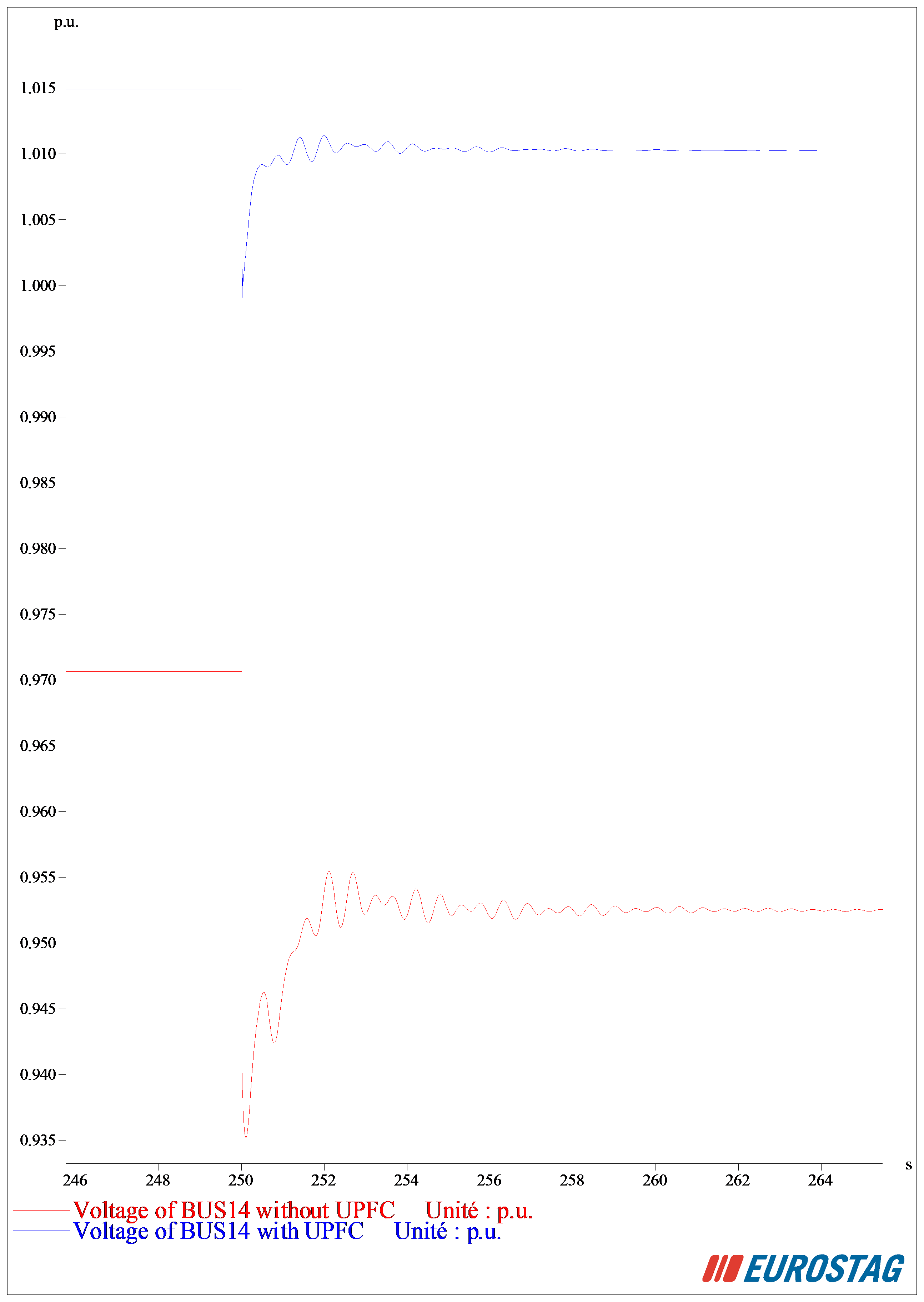 Figure 7. Temporal evolution of voltage at bus14 for 20 % of load increase with and without UPFC
The test network along with UPFC at different locations is tested now for comparison purpose. In addition to line 9-14, we choose two placements in the transmission system: lines 1-2 and 2-3 which are intended for transmitting the highest amount of reactive and active powers. Thereby, enhancing power flowing in these lines can be effective in improving voltage stability of the whole network. Figure 8 and Figure 9 illustrate the temporal evolution of voltage at bus1 and bu2 respectively. It should be noted that the implementation of UPFC in line 1-2 has considerably damped voltage oscillations compared to the other cases. While, this location had no effect on the voltage magnitude as shown in Figure 10. UPFC in line 9-14 gave best voltage levels at all network buses than when it is incorporated in line 2-3, where we obtained the lowest voltage magnitudes.
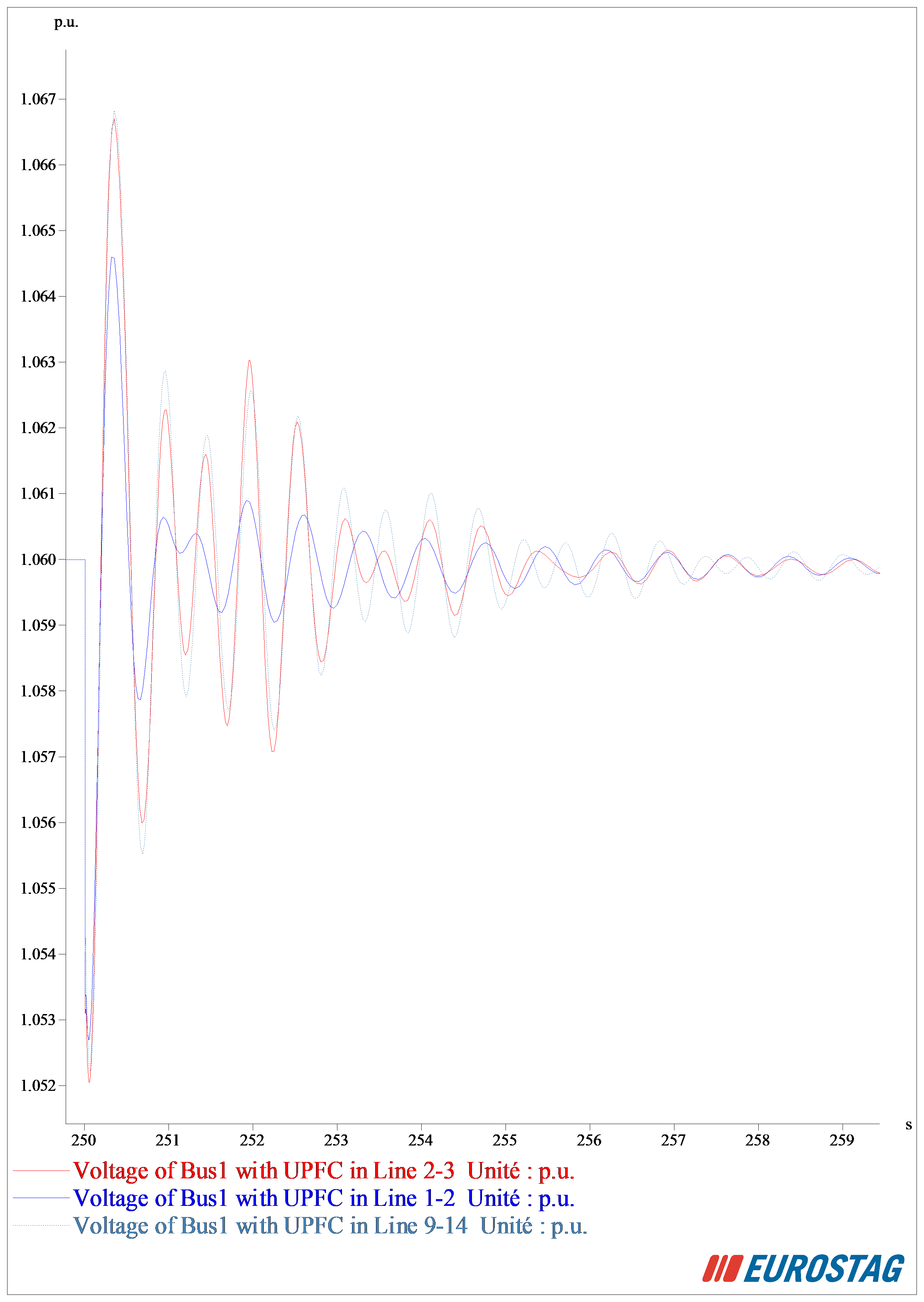 Figure 8. Temporal evolution of voltage at bus 1 for 20% of load increase with different locations of UPFC.
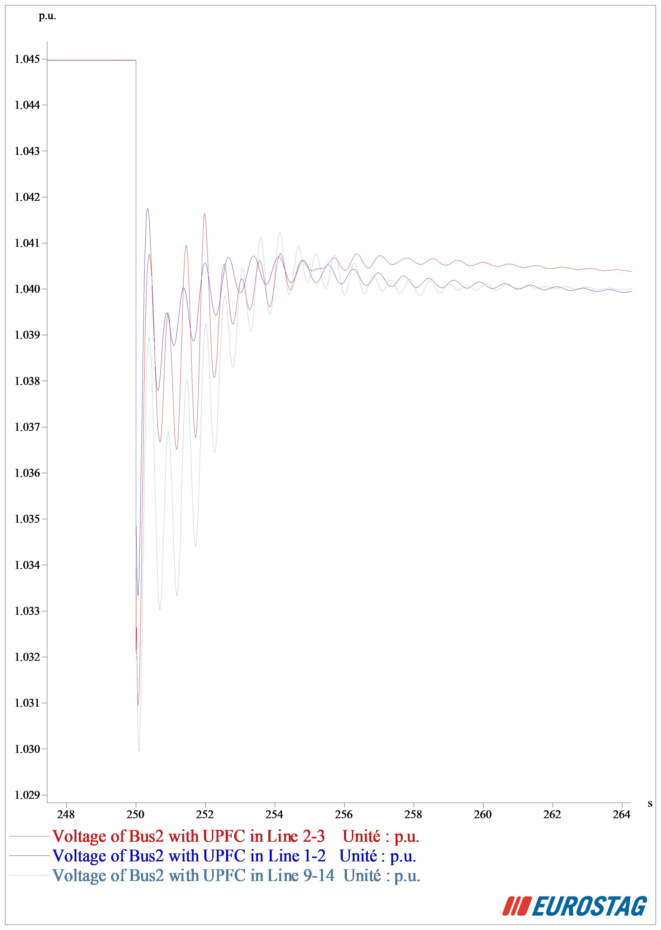 Figure 9.Temporal evolution of voltage at bus 2 for 20% of load increase with different locations of UPFC.
Figure 11 illustrates the active power losses of the system. It is clearly observable that the active power losses had the lowest value in the case of UPFC inserted through line 9-14, it is about 13.5MW. However, a large amount of active losses is detected with line 2-3 placement and about 14 MW in line 1-2 case.
Now, we evaluate the impact of UPFC location on the loadability margin of the power system. From Table 1, we can note that the contribution of the controller in improving the maximum loading capability was very meaningful when installing in the distribution system. In fact, it was able to increase the loadability margin in zone A from 48% to 59% and from 39% to 70% in zone B. As for the whole network, it became able to maintain a stable state up to 33.5% of load increase while its maximum loadability was about only 25% before compensation. Nevertheless, when introduced in the transmission system, UPFC was less effective in increasing loadability margin. That was observable notably in line 2-3, where only the loading capacity of zone A; reached a higher percentage compared to the case without UPFC.
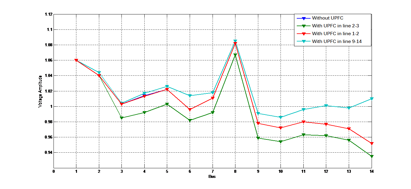 Figure 10.Voltage profiles of IEEE 14-Bus system for 20% load increase with different locations of UPFC
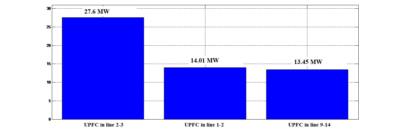 Figure 11. Active power losses for 20% load increase with Different UPFC Locations.
Table 1. Load ability Margins with Different Locations of UPFC.
| Network Zone | Loadability Margin in % | |||
| Without UPFC | With UPFC in line 2-3 | With UPFC in line 1-2 | With UPFC in line 9-14 | |
|
Zone A
|
48 | 52 | 55 | 59 |
|
Zone B
|
39 | 39 | 39 | 70 |
| Zones A&B
|
25 | 25 | 32 | 33.5 |
Conflict of Interest
The authors declare that there is no conflict of interests regarding the publication of this paper.
5. Conclusion
In this paper, the impact of the proper installation of UPFC on improving voltage stability has been investigated. The placement of UPFC is done by using a numerical simulation based method. The identification of the critical zone of the system can determine the best location of the hybrid device. Then, the performance of the proper placement is compared to different selected locations in the system for justification purpose. It was found that UPFC incorporated through line 9-14 in the critical zone, helps in improving voltage magnitude, reducing active power losses as well as increasing maximum loading capacity of the system. However, the integration of the controller in the transmission system gave rapid and well- damped oscillations. Thereby, the optimal placement of the UPFC is highly dependent on the objective of the integration.
- H. Jmii, A. Meddeb, S. Chebbi, “Efficiency Limits of SVC in Improving Voltage Stability,”3rd Inter, conf, GEEE, April, 2016, Hammamet, Tunisia.
- Singh, “Applications of FACTS Controllers in Power Systems for Enhance the Power System Stability: A State-of-The-Art,” International Journal of Reviews in Computing, Vol. 6, 15th July 2011.
- Gupta, P.R. Sharma,“ Optimal location and setting of SVC and TCSC devices using non-dominated sorting particle swarm optimization,” Electric Power Systems Research, 2009.
- Kundur., “Power system stability and control,”McGraw-Hill, Inc., 1993.
- Amara, H. Hsan, “Power system stability improvement by FACTS devices: a comparison between STATCOM, SSSC and UPFC,” 1st International Conference on Renawble Energies and Vehicular Technology, 2012.
- A. Abido, “Power System Stability Enhancement using FACTS Controllers: A Review,” The Arabian Journal for Science and Engineering, vol.34, no1B, Apr 2009.
- Gyugyi L., “ United power flow control concept for flexible AC transmission systems,” Proceedings of IEE Part-C IEE Proceedings of Generation, Transmission and Distribution, 139:323–331, 1992.
- Singh, H. Qazi, M. Ghandhari, “ Load curtailment minimization by optimal placement of United Power Flow Controller,” International Transactions on Electrical Energy systems, 2016.
- G. Mathad, B.F. Ronad, S.H. Jangamshetti, “Review on Comparison of FACTS Controllers for Power System Stability Enhancement,” International Journal of Scientific and Research Publications, vol. 3, Issue 3, March 2013
- P. Zhang, Ch. Rehtanz, B. Pal, “ Flexible AC Transmission Systems: Modeling and Control,” 2nd Edition, Springer, Feb 2012.
- H. Wu, Z. Lu, M.S. Li, T.Y. Ji, “ Optimal Placement of FACTS Devices by A Group Search Optimizer with Multiple Producer,” IEEE trans, 2008.
- Gupta, R. Tripathi, R. Shukla, “ Voltage stability improvement in power systems using FACTS controllers: State-of-the-art review,” https://www.researchgate.net/publication/251987213, 2010.
- Benaissa, S. Hadjeri, S.A. Zidi, “Impact of PSS and SVC on the Power System Transient Stability,” Advances in Science, Technology and Engineering Systems Journal, pp. 562-568 , Vol. 2, No. 3, 2017.
- Sanjari, O. Mousavi, G. Gharehpetian, “Assessing the risk of blackout in the power system including HVDC and FACTS devices,” European Transactions on Electrical Power, 2012.
- Shaheen, G. Rashed, S. Cheng, “Application of differential evolution algorithm for optimal location and parameters setting of UPFC, 19:911–932, 2009.
- Jupta, P.R. Sharma,“Optimal Placement of FACTS Devices for Voltage Stability Using Line Indicators,” IEEE trans, 2012.
- Wang,“Applications of modelling UPFC into multi-machine power systems,” IEE Proceedings online no. 19990170, DOI: 10.1049/ip-gtd:19990170, 1999.
- Ray, J.O. Chandle , “Voltage Stability Enhancement during Excess Load Increments through Optimal Location of UPFC Devices,” IEEE International Conference on Technological Advancements in Power & Energy, 2015.
- Jupta, P.R. Sharma, “ Static and transient stability enhancement of power system by optimally placing UPFC (Unified Power Flow Controller),” IEEE trans, 2013.
- Lee, J. Liu, C. Chu, “ Modelling and locating united power-flow controllers for static voltage stability enhancements,” International Transactions on Electrical Energy systems, 2012.
- Bhattacharyya, V.K. Gupta, S. Kumar, “UPFC with series and shunt FACTS controllers for the economic operation of a power system,” Ain Shams Engineering Journal, 2014.
- I. Shaheen, G.I. Rashed, S.J.Cheng, “Optimal Location and Parameters Setting of Unified Power Flow Controller Based on Evolutionary Optimization Techniques,” IEEE trans, 2007.
- Jmii, A. Meddeb, S. Chebbi, “Proper Placement of UPFC for the Improvement of Voltage Stability of IEEE-14 Bus System,” 4th International Conference on Control Engineering & Information Technology (CEIT) Tunisia, Hammamet, December 2016.
- Mathur, R. Varma, “Thyristor-Based FACTS Controllers for Electrical Transmission Systems,” J. Wiley & sons.
- Rath, B. Sahu, P. Dash, “Power System Operation and Control using FACTS Devices,” International Journal of Engineering Research & Technology (IJERT), Vol. 1, Issue 5, July 2012.
- Khan, M. Mallick, M. Rafi, M. Mirza, “Optimal placement of FACTS controller scheme for enhancement of power system security in Indian scenario,” Journal of Electrical Systems and Information Technology 2, pp.161–171, 2015.
- Aboreshaid, S.,Billinton, R., “Probabilistic evaluation of voltage stability,” IEEE Trans.PowerSyst.14(February(1)), pp. 342–348,
- Morsli, “Robust Control of UPFC in MultiMachines Power Network,” M.S. thesis, Dept. Electron. Eng., Oran Univ., Algeria, 2012.
- Meddeb, H. Jmii, S. Chebbi, “ Comparison of UPFC, TCSC and SVC for Improving Voltage Stability,” 3rd Inter, conf, ACECS , March, 2016, Hammamet, Tunisie.
- Farrag, G. Putrus, “An on-line training radial basis function neural network for optimum operation of the UPFC,” EUROPEAN TRANSACTIONS ON ELECTRICAL POWER, 21, pp.27–39, 2010.
- Milano, “Power System Modelling and Scripting,” Springer, ETSII, University of Castilla – La Mancha 13071, Ciudad Real Spain 2010.
- Eurostag, Eurostag Software Release Notes, Tractebel-EDF, Release 5.1, Dec 2010.