Modelling and Analysis of Radial Flux Surface Mounted Direct-Driven PMSG in Small Scale Wind Turbine

Adv. Sci. Technol. Eng. Syst. J. 2(6), 94–99 (2017);
 DOI: 10.25046/aj020612
This paper presents the modelling and analysis of permanent magnet synchronous generator (PMSG) which are used in direct driven small scale wind turbines. The 3 kW PM generator which is driven directly without gear system is analyzed by Ansoft Maxwell 2D RMxprt. The performance analysis of generator includes the cogging torque in two teeth, induced coil voltages under load, winding current under load, airgap flux density distribution and so on. The modelling analysis is based on the 2D finite element techniques. In an electrical machine, an accurate determination of the geometry parameters is a vital role. The proper performance results of 3kW PMSG in small scale wind turbine can be seen in this paper.
1. Introduction
In this century, wind power generation has become the most powerful influences in all over the world[1]. The variable speed wind turbines have been more popular in nowadays because it has some advantages compare to fixed speed wind turbines such as less mechanical stress, higher efficiency, higher power quality and so on[2].
The several advantages of variable speed wind turbines are reduced mechanical stress and optimized power capture.In variable speed wind turbines, two types of generators are usually employed in the small scale wind turbine such as induction generators (IGs) and permanent magnet synchronous generators (PMSGs)[3].
Recently, in the WTs, the PMSGs have been more attractive the IGs because of direct drive and high efficiency. Moreover, the PMSGs have the high torque density and the power factor characteristics. The direct-drive train wind power on system generation can be seen in Figure 1.Four main components are contained in this system and the PMSG connects to the grid through a back to back converter, converting the mechanical energy produced by the wind turbine to the electrical energy[4].
Two type of rotor position can be used in PMSG family such as outer rotor and inner rotor. In this study, the small outer rotor surface mounted generator is adopted for modelling and analysis because of the easier construction. In conventional machines, the magnetic field is in the radial direction. These types of machines are referred to as radial flux machines (RFM) whereas the magnetic field of axial flux machine (AFM) is in the axial direction [5].
The small scale generators can be used for remote areas. The American Wind Energy Association (AWEA) defines small scale wind generator as those whose power reaches up to 100 kW.
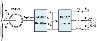 Figure 1. Configuration of a direct-drive PMSG system
The 2D analysis of outer rotor surface mounted PM generator is studied in this paper. The output power is 3 kW, rated mechanical speed is 250 rpm and number of poles are 34, respectively.
2. Modelling of PMSG by Maxwell 2D RMxprt
2.1. The geometry model of PMSG
In this study, outer rotor radial flux surface mounted direct-driven PMSG are employed. The radial flux outer-rotor PMSG, 17 pole pairs, are considered. The advantages of outer rotor PMSG compared to inner-rotor PMSG is that the magnets are easily attached to the rotor surface.Permanent magnet synchronous generators (PMSGs) have two parts; stator and rotor. Rotor has permanent magnets to create constant magnetic field in electrical machine[6]. Other time and space varying magnetic field is created with the stator windings. The geometry model of outer rotor radial flux surface mounted PMSG is shown in Figure 2.
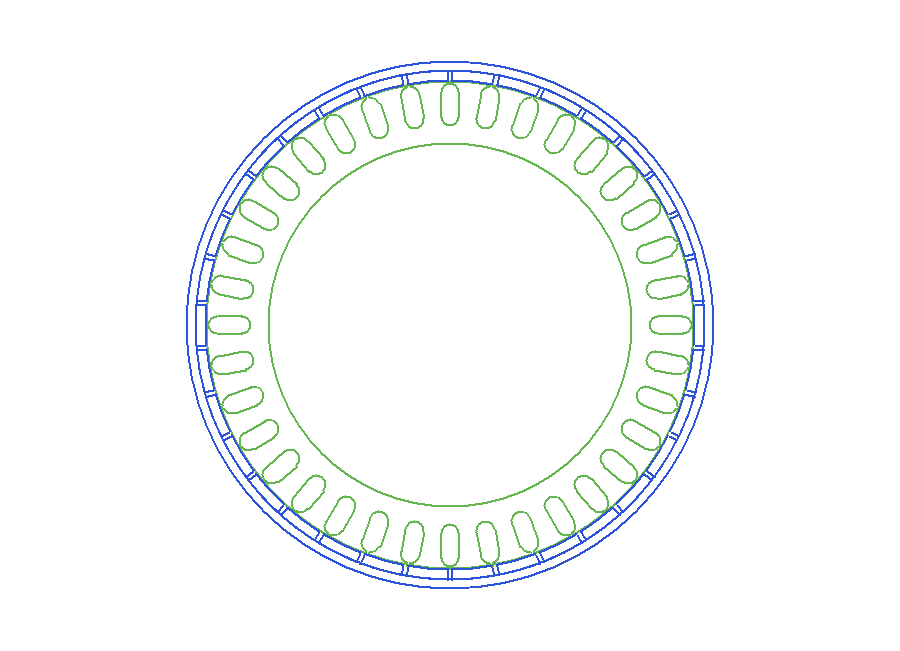 Figure 2. The geometry model of outer rotor PMSG
2.2. Maxwell 2D Model of PMSG
In this model, 3 kW small scale DDPMSG for wind turbine are designed. The main parameters of the DDPMSG are shown in Table 1.
Table 1: Major Parameters of DDPMSG
| Parameters | Unit | Quantities |
| Rated output power | kW | 3 |
| Rated phase voltage | V | 220 |
| Control Type | – | AC |
| Rated power factor | – | 0.9 |
| Rated speed | rpm | 250 |
| Number of poles | – | 34 |
| Number of phases | – | 3 |
| Permanent magnet | – | NdFeB |
| Rotor Position | – | Outer Rotor |
Parametrical analysis procedure are considered. Firstly, the stator steel type, rotor steel type and the magnet type should be determined from RMXprt library and the diameters of stator and rotor, the thickness of yoke and the airgap are roughly defined. And then, design calculations and modelling analysis are started. Table 2 represents the model design results of 3kW PMSG which are based on electrical machine theory.
Table 2: Design Results of DDPMSG
| Parameters | Unit | Quantities |
| Phase | 3 | |
| Pole | 34 | |
| Stator Slot | 36 | |
| Conductors per slot | 24 | |
| Length of Rotor | mm | 60 |
| Outer Diameter of Rotor | mm | 512 |
| Inner Diameter of Stator | mm | 358 |
| Thickness of Magnet | mm | 10 |
| Rotor Pole Embrace | – | 0.9 |
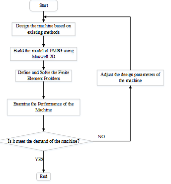 Figure 3. Design flow chart of the model for the PMSG
According to the proposed flow chart of the PMSG shown in Figure 3, a PMSG of 3kW is modelled. In this model, RMXprt (XG196/96) magnets are radially magnetized and are mounted on the surface of the rotor and the steel type of D21-50 is chosen for stator and rotor laminations. To reduce the risk of partial demagnetization, an accurate prediction of magnet loss at the design stage is an important role. It can not only give a better efficiency but also may prevent excessive temperature rise in magnets [6]. Considering the almost fixed magnetic field, the rotor core is made of solid steel and the stator core is made of electrical steel with 36 slots for three phase windings. The prototype model of 3 kW DDPMSG in wind energy conversion system (WECS) can be seen in Figure 4.
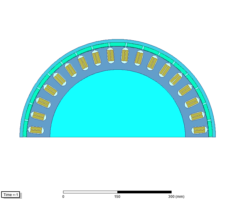 Figure 4. Maxwell 2D Model of PMSG Prototype
3. General Characteristics of PMSG
Nowadays, the DDPMSG is widely used in wind power application which has some advantages compare to other type of generators. The Maxwell 2D stator winding construction of this model is presented in Figure 5.
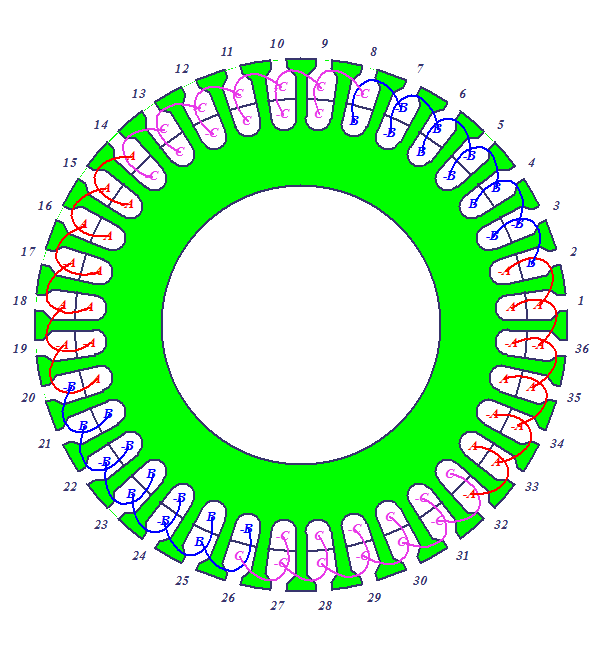 Figure 5. The stator winding connection of 3 kW PMSG
Moreover, the hysteresis (B-H) curves which express the relation between the flux density B and the magnetic field intensity H of the stator and rotor steel is an important characteristics of PMSG[7]. The stator and rotor steel type B-H curve of the FEM model is shown in Figure 6. Figure 7 represents the relationship between the flux density B and the magnetic field intensity H of magnet XG 196/96 from FEM analysis.
3.1. Magnetic Flux and Flux Density Distribution
With the application of high energy-product rare-earth PM to electric machines, many 2-D analytical models have been proposed for the direct driven PM machines and most of them focus on the field distribution and airgap flux density distribution. ANSYS Maxwell 2D RMxprt software is universal finite element analysis software of magnetic field calculation [8].
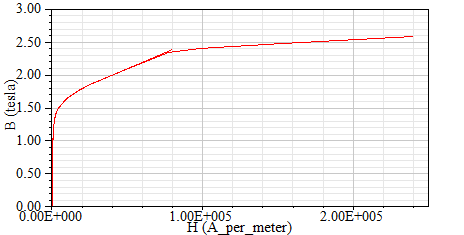 Figure 6. B-H Curve of Stator and Rotor Steel D21-50 RMxprt
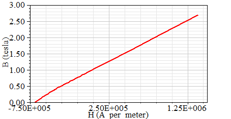 Figure 7. B-H Curve of Magnet (XG196/96) RMxprt
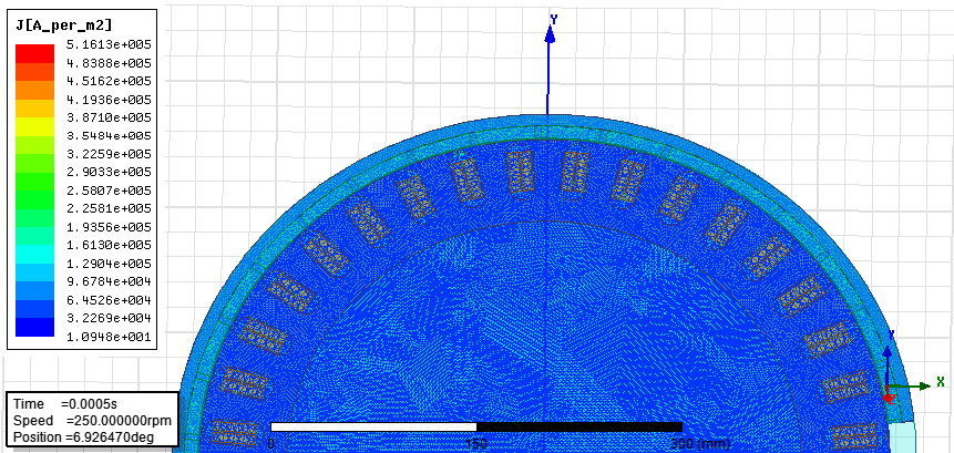 Figure 8. Meshing Plot of J Vector by Maxwell 2-D PMSG Model
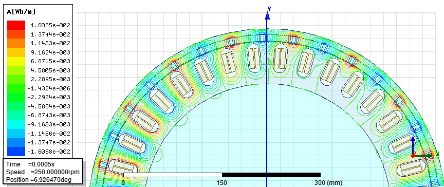 Figure 9. Flux Distribution in Maxwell Design
The model meshing plot of J vector can be seen in Figure 8. And then, The Maxwell 2D analysis of the important parameters of PMSG such as the flux distribution, field distribution and magnetic flux density distribution are shown in Figure 9, Figure 10 and Figure 11, respectively.
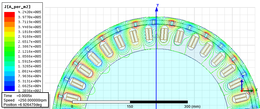 Figure 10. Field Distrubtion of J vector
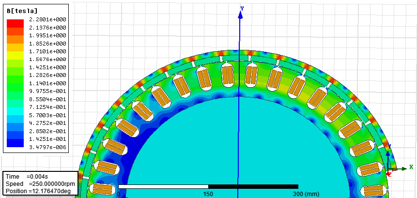 Figure 11. Magnetic flux density distribution of Maxwell 2-D
3.2. Mathematical Models of PMSG
Mathematical model of PMSG is usually given in rotating reference frame of machine. The quadrature (q) axis and the direct (d) axis PMSG equations are given below. Figure 12 and Figure 13 show equivalent circuit of PMSG in d-q frame [9].
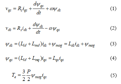
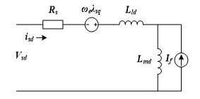 Figure 12. The d- axis equivalent circuit of PMSG
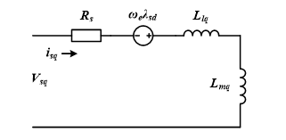 Figure 13. The q- axis equivalent circuit of PMSG
3.3. Finite Element Model Analysis
The two dimensional finite element model of the PMSG of 3kW with surface mounted PM is set up by using Maxwell 2D RMxprt. There are four main modelling processes such as inputting the data of the geometrical size of the PMSG, defining the stator, rotor, airgap, windings and PM properties, defining the boundary condition and generating finite element mesh.
After finishing these four steps, the proposed PMSG could be the modeled and solved though the FEA at different operation modes.
4. Performance Analysis of DDPMSG
The small scale wind turbine is directly connected to PMSG which receives wind turbine torque as a mechanical input and converts it into the electrical input; however, this electrical energy has a variable amplitude and frequency [10]. The FEA model of electromagnetic field is built by Ansoft Maxwell 2D and the simulation time is taken some hours [11]. To visualize magnetic fields and predict magnetic forces, Maxwell 2D program can be used.
The modelling analysis of 3 kW PM generator for wind energy conversion system is presented. The key characteristics of DDPMSG such as the cogging torque, air-gap flux density, induced coil voltage at rated speed and winding current under load are analyzed by Maxwell 2D RMxprt. Figure 14 shows the curve of cogging torque in two teeth. In PMSG, the cogging torque is generated by the sum of a series of cogging torque harmonics [12]. The cogging torque in PM machine can be expressed as:
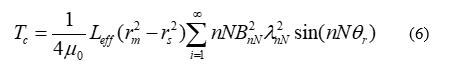 Where N is the least common multiple of the number of poles and stator slots of the PMSG. The cogging torque causes noise and vibration in PMSG at low speed and the direct drives applications. The frequency of cogging torque is the proportional to the least common multiple of the number of poles and the stator slots of the PMSG. The results obtained by using 2D Maxwell model provide sufficient accuracy with measured ones in a PMSG prototype.
In this FEM model, the proper simulation results of DDPMSG as shown in Figure 14 to Figure 19.The variation of cogging torque with respect to electrical degree can be seen in Figure 14 that generated the 3 kW FE model of Maxwell 2D.
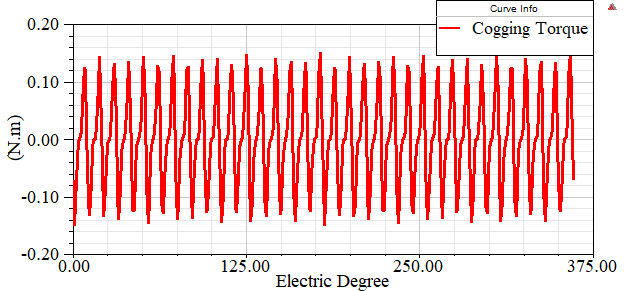 Figure 14. Cogging torque in two teeth of 3kW PMSG
The relationship between the winding voltage under load condition and electrical degree can be determined by the FEM analysis represented in Figure 15. The induced winding voltage of rated speed is shown in Figure 16.
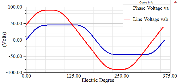 Figure15. Winding Voltage under Load
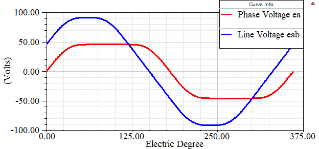 Figure 16. Induced Winding Voltage of Rated Speed
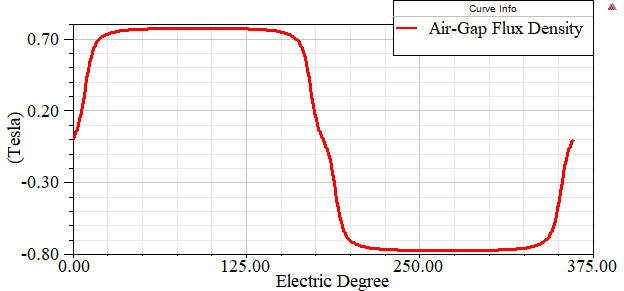 Figure 17. Air –Gap Flux Density
In this model, the maximum air-gap flux density distribution can be generated about 0.7 T by Maxwell 2D.The important parameter of air-gap flux density distribution of PMSG as shown in Figure 17. The performance curves of induced coil voltage at rated speed and the winding current under load are represented in Figure 18 and Figure 19,respectively.
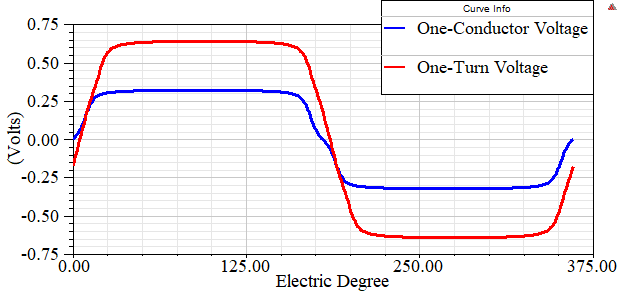 Figure 18. Induced Coil Voltage at Rated Speed
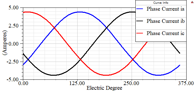 Figure 19. Wndinding Current under Load
Moreover, the transient analysis of 3 kW DDPMSG are discussed in this paper. The transient plots of main parameters in wind generator like the induced winding voltage of phase A,B and C,the comparison of solid losses and core loss,the moving torque of PMSG and the flux distributions in machine are generated by Ansoft Maxwell 2D RMxprt. All of the transient analysis curves are shown below.
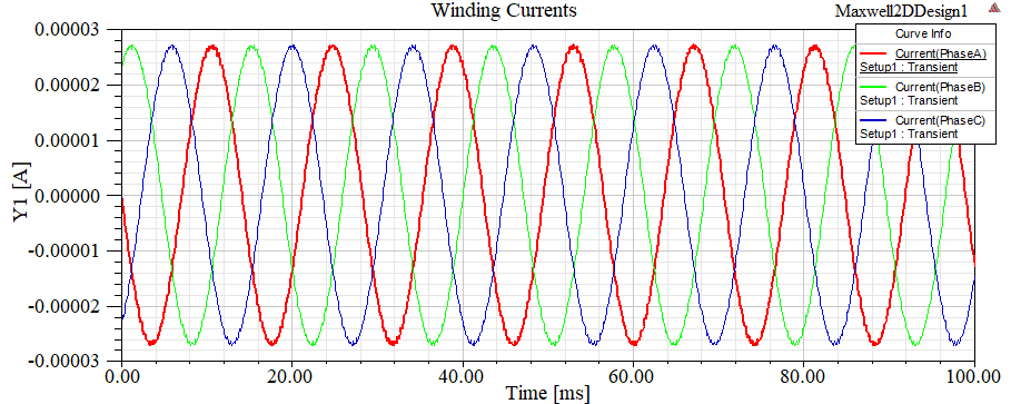 Figure 20. Induced Windind Voltages of Phase A, B, and C
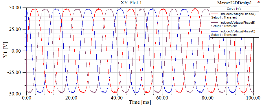 Figure 21 .Comparison of Core loss and Solid loss
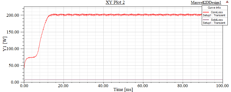 Figure 22. Transient Moving Torque of PMSG
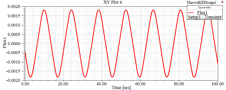 Figure 23. Flux analysis of Generator
5. Conclusions
The 2D modelling analysis of surface mounted PM generator in small scale wind turbine is studied in this paper. There are two main parts of the performance analysis in electrical machine such as the FEM performance curves and the transient curves. In this paper, the key machine parameters analysis are discussed by Ansoft Maxwell 2D RMxprt. To construct the machine model, Maxwell 2D RMxprt is to be a competent and valuable tool. Moreover, the analysis results obtained by using 2D finite element model provided sufficient accuracy with a PMSG prototype. According to the FEM modelling analysis and transient analysis, the design of 3 kW PMSG in this paper is suitable for small wind power applications.
Nomenclature
Cogging torque
Effective length of the PMSG
Inner diameter of the magnet
Outer diameter of the stator
Q-axis magnetizing inductance
D-axis magnetizing inductance
Electrical angular speed
Electromagnetic Torque of PMSG
D-axis stator inductance
Q-axis stator inductance
Stator resistance
Q-axis stator voltage
D-axis stator voltage
D-axis flux linkage
Q-axis flux linkage
Permanent magnet flux linkage
D-axis stator current
Q-axis stator current
Conflict of Interest
The authors declare no conflict of interest.
Acknowledgment
The lead author is grateful to her supervisor for supporting to develop this study by providing the suitable suggestions.
- Umashankar, D.P.K.a., Wind Energy Systems and Applications. 2013, Narosa.
- Yasa, Y. and E. Mese. Design and analysis of generator and converters for outer rotor direct drive gearless small-scale wind turbines. in Renewable Energy Research and Application (ICRERA), 2014 International Conference on. 2014.
- Alnasir, Z. and M. Kazerani, An analytical literature review of stand-alone wind energy conversion systems from generator viewpoint. Renewable and Sustainable Energy Reviews, 2013. 28: p. 597-615.
- Yan, J., et al., Control of a grid-connected direct-drive wind energy conversion system. Renewable Energy, 2014. 66(Supplement C): p. 371-380.
- Faiz, J., et al. Design of a radial flux permanent magnet wind generator with low coercive force magnets. in 2016 2nd International Conference on Intelligent Energy and Power Systems (IEPS). 2016.
- Nair, S.S., et al., Computationally efficient 3D analytical magnet loss prediction in surface mounted permanent magnet machines. IET Electric Power Applications, 2017. 11(1): p. 9-18.
- Ducar, I.M. and C.P. Ion. Design of a PMSG for micro hydro power plants. in Optimization of Electrical and Electronic Equipment (OPTIM), 2012 13th International Conference on. 2012.
- Zhang, Z., et al. Study on circle-annulus meshing methods using ANSYS software and its application in motor electromagnetic field analysis. in Electrical and Control Engineering (ICECE), 2011 International Conference on. 2011.
- Ugalde-Loo, C.E., et al. Analysis and efficient control design for generator-side converters of PMSG-based wind and tidal stream turbines. in Power Systems Computation Conference (PSCC), 2014. 2014.
- Fazli, N. and J. Siahbalaee. Direct torque control of a wind energy conversion system with permanent magnet synchronous generator and Matrix Converter. in 2017 8th Power Electronics, Drive Systems & Technologies Conference (PEDSTC). 2017.
- Alam, F.R. and K. Abbaszadeh, Magnetic Field Analysis in Eccentric Surface-Mounted Permanent-Magnet Motors Using an Improved Conformal Mapping Method. IEEE Transactions on Energy Conversion, 2016. 31(1): p. 333-344.
- Liu, T., S. Huang, and J. Gao. Optimization of a direct-drive wind power generation system by using PMSG. in Power Engineering, Energy and Electrical Drives (POWERENG), 2011 International Conference on. 2011.