Flexible Aperture Tuning Solution for Cellular Main Antenna in Metallic Back Cover Mobile Phone

Adv. Sci. Technol. Eng. Syst. J. 2(6), 49–55 (2017);
 DOI: 10.25046/aj020606
Metal housing has been used extensively on portable communication devices such as on mobile phones and tablets. The choice of metal housing ranges from metallic rim to metallic back cover. This metal housing tends to improve the outlook appearance of the mobile devices, and add mechanical strength towards the mobile devices. However, from the aspect of the communication antenna, the metal housing often posts great challenges towards the flexibility in antenna design and reduction in antenna performance. This paper presents an approach to overcome the challenges by integrating the metal housing of the mobile phone as part of the antenna, along with the introduction of tunable antenna concept to provide different forms of Aperture Tuning to the Cellular Main Antenna, to satisfy its wide frequency band coverages for the 2nd, 3rd and 4th Generation (2G, 3G and 4G) mobile network.
1. Introduction
Over the years, there had been a popular trend for mobile phones to be equipped with metal housing. The metal housing often comes in different forms, which examples are as shown in Figure 1. One form of metal housing is the Closed Metal Ring as shown in Figure 1(a), with a metal ring running around the edges of the mobile phone. Another type of metal housing, quite similar to the Closed Metal Ring, is the Broken Metal Ring (with open slot) as shown in Figure 1(b). In the Broken Metal Ring, there are slots cutting on the metal ring, dividing the metal ring into two or more sections. In recent years, there is another type of metal housing that has been becoming popular. This metal housing comes in the form of a Metallic Back Cover as shown in Figure 1(c). The use of metal housing on mobile phone tends to improve the outlook appearance of the mobile phone. Apart from that, the robustness of the metal housing tends to add mechanical strength to the mobile phone. However, the use of metal housing on mobile phone often post disadvantages towards the mobile phone antenna. These disadvantages include introducing unwanted coupling towards the antenna, creating a shielding effect over the antenna hence reducing the sensitivity of the antenna etc. Additionally, maintaining the aesthetics of the metal housing on the mobile phone comes with an antenna design flexibility cost.
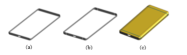 Figure 1. Different forms of metal housing: (a) Closed Metal Ring; (b) Broken Metal Ring (with open slot); (c) Metallic Back Cover;
This paper serves as an extension of work originally presented in 2017 11th European Conference on Antennas and Propagation (EuCAP2017) [1]. This paper presents a flexible Aperture Tuning solution [2 – 4] for the cellular Main Antenna in a Metallic Back Cover mobile phone, to provide coverage for multi frequency bands in the frequency range of 700MHz to 960MHz (LTE700, GSM850, GSM900), 1710MHz to 2170MHz (DCS1800, PCS1900, WCDMA2100) and 2300MHz to 2690MHz (LTE2300, LTE2600). The flexible Aperture Tuning solution as proposed in this paper aims to overcome the disadvantages post by the metal housing as mentioned above. In the earlier paper [1], the flexible Aperture Tuning solution for the cellular Main Antenna has been briefly introduced, along with the Free-Space passive measurement data of the Main Antenna’s Reflection Coefficient S11 and Total Efficiency. This paper will further elaborates on the concept of the different Aperture Tuning solutions that are deployed at different parts of the Main Antenna for tuning the antenna’s Low (700 – 960MHz) Band, Mid (1710 – 2170MHz) Band and High (2300 – 2690MHz) Band. Besides the Free-Space passive measurement data, this paper also presents the active measurement data (Total Radiation Power TRP) taken with the mobile phone mockup in the Free-Space and Phantom Head & Hands conditions.
2. Metallic Back Cover Mobile Phone Mockup
2.1. Metallic Back Cover
The metal housing for the mobile phone presented in this paper takes the form of a Metallic Back Cover, as mentioned in Figure 1(c). Figure 2 shows pictures illustrating the exterior and interior appearance of the Metallic Back Cover. From the exterior appearance shown in Figure 2(a), the Metallic Back Cover seems to be divided into three sections, namely Top-section, Mid-section and Bottom-section. In between each section, there is a plastic slot (at 1mm wide) running across the Metallic Back Cover. However, from the interior appearance shown in Figure 2(b), it can be seen that the Mid-section and Bottom-section of the Metallic Back Cover are actually joined together internally. This makes the slot at the Bottom-section more like a Closed-end slot instead of a through slot as seen at the Top-section. The overall dimension of the Metallic Back Cover is 144mm by 70mm by 6.5mm, which is suitable for mobile phone with 5.5inch display.
- Exterior appearance
- Interior appearance
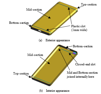 Figure 2. Metallic Back Cover Interior appearance
In this proposed solution, the Main Antenna is located at the bottom section of the mobile phone. The entire Bottom-section metallic cover and partial of the Mid-section metallic cover are integrated as part of the Main Antenna design. Figure 3 shows pictures mainly highlighting the interior appearance at the bottom section of the Metallic Back Cover. There is a Capacitive Feed Patch located near the bottom left corner of the Metallic Back Cover. This Capacitive Feed Patch is a thin layer of conductive rectangular patch, separated from the inner surface of the Metallic Back Cover by a thin layer of plastic substrate with thickness of 0.5mm. The Capacitive Feed Patch is positioned on the Bottom-section side of the Metallic Back Cover in a way such that the edge of the Capacitive Feed Patch will align well with the edge of the Closed-end slot, as can be seen in Figure 3. Figure 3 also highlights the installation of a Tuner Board on the inner surface of the Metallic Back Cover. The Tuner Board is a tiny piece of Printed Circuit Board (PCB) that is used to house a Tunable Capacitor TC1. The Tuner Board is fully grounded onto the Mid-section of the Metallic Back Cover, positioned just by the edge of the Closed-end slot. The output of the Tunable Capacitor TC1 is bridged across the slot and get into direct contact with the Bottom-section of the Metallic Back Cover.
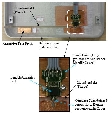 Figure 3. Capacitive Feed Patch and Tuner Board on Metallic Back Cover
2.2. Main Antenna Printed Circuit Board (PCB)
Figure 4 shows partial of the Main Antenna Printed Circuit Board (PCB) used in the mobile phone mockup, mainly highlighting the environment in the Main Antenna region at the bottom section of the mobile phone. The PCB is equipped with a Type-C Micro-USB and a speaker which are components that are commonly found at the bottom section of mobile phone. On the PCB, there is a Feed-Pin that is traced to the source of the Main Antenna. The Feed-Pin can be in the form of a pogo-pin or spring contact to establish a direct connection with the Capacitive Feed Patch at the location (red-dot) as highlighted in Figure 4. Located next to the Feed-Pin is Gnd-Pin1, which is traced to a Tunable LC Resonant Circuitry, with reference to the common ground. This Tunable LC Resonant Circuitry is made up of a shunt inductor in parallel with a shunt Tunable Capacitor TC2, to provide Aperture Tuning to the Main Antenna. The Gnd-Pin1 can be in the form of a pogo-pin or spring contact to make direct contact with the Bottom-section metallic cover at the location (blue-dot) as indicated in Figure 4. Located above Gnd-Pin1 on the PCB is Gnd-Pin2 which is traced to a standalone Tunable Capacitor TC3 connecting to the reference ground. This standalone Tunable Capacitor is meant for providing Aperture Tuning to the Main Antenna. The Gnd-Pin2 makes direct connection with the Mid-section of metallic cover at the location (purple-dot) as indicated in Figure 4. To the left of Gnd-Pin2, located near the speaker is Gnd-Pin3 which is connected directly to the reference ground. Gnd-Pin3 on the PCB is meant to make direct connection with the Mid-section of metallic cover at the location (green-dot) next to the Tuner Board as shown in Figure 4. This arrangement of the grounding connections between the respective ground pins (Gnd-Pin1, Gnd-Pin2 and Gnd-Pin3) on PCB and the Metallic Back Cover has integrated the Metallic Back Cover as part of the Main Antenna design. The three Tunable Capacitors (TC1, TC2 and TC3) as mentioned above on the Metallic Back Cover and Main Antenna PCB are Micro-Electro-Mechanical Systems (MEMS) based variable capacitors. Each capacitor has 16 different states of capacitance value ranging from 0.3pF to 2.97pF programmed in its register. The proposed tunable solution for the Main Antenna in this paper is not limited to the technology or type of the Tunable Capacitor.
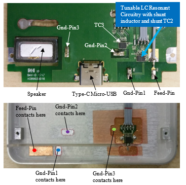 Figure 4. PCB layout for the Main Antenna and integrating the Metallic Back Cover as part of the Main Antenna design
3. Flexible Aperture Tuning Solution for Main Antenna
The Main Antenna of the mobile phone has operating frequency bands that are divided into the Low Band, the Mid Band and the High Band. The Low Band covers frequency range from 700MHz to 960MHz, the Mid Band covers frequency range from 1710MHz to 2170MHz and the High Band covers frequency range from 2300MHz to 2690MHz. These ranges of frequency bands are sufficient to provide coverage for the 2G, 3G and 4G network. The Aperture Tuning of the Main Antenna as proposed in this paper will be broken down to sections with respect to the following bands: Low Band, Mid Band and High Band.
3.1. Low Band Tuning (700MHz to 960MHz)
The proposed Main Antenna solution is fed using the Capacitive-Fed Coupling Technique [5 – 6] to the Bottom-section metallic cover via the Capacitive Feed Patch as mentioned above in Figure 3. Energy from the Capacitive Feed Patch is coupled onto the Bottom-section metallic cover. Current on the Bottom-section metallic cover will then flows in the direction as indicated by the yellow-coloured arrow (as shown in Figure 5(a)) to Gnd-Pin3 on the Main Antenna PCB. This forms a Loop Antenna for the Low Band of the Main Antenna. Aperture Tuning is applied to this Loop Antenna at Gnd-Pin1, via the Tunable LC Resonant Circuitry [2 – 4] (as mentioned in Figure 4) which equivalent circuit is as shown in Figure 5(b). The resonance at the Low Band of the Main Antenna can be made to shift within the frequency range of 700MHz to 960MHz by tuning the capacitance value of the Tunable Capacitor TC2 on the PCB. In tuning the Low Band of the Main Antenna, the capacitance value of the Tunable Capacitor TC1 on the Metallic Back Cover and the Tunable Capacitor TC3 at Gnd-Pin2 on the PCB are kept constant at 2.97pF and 0.66pF respectively.
- Current flow for Low Band Tuning
- Equivalent circuit of Tunable LC Resonant Circuit
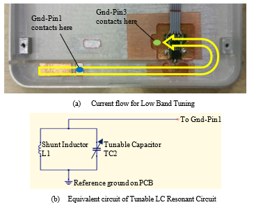 Figure 5. Low Band Tuning of Main Antenna
Figure 6 shows plots of the passive measurement result for the Low Band Tuning of the Main Antenna, in Free-Space condition. Figure 6 (a) is the Reflection Coefficient S11 of the Main Antenna measured using a Network Analyzer. Figure 6(b) shows plots of the Total Efficiency of the Main Antenna in the Low Band region, measured in an Anechoic Over-the-Air (OTA) Chamber. From the two plots shown in Figure 6, it can be seen that three different
- Reflection Coefficient S11 in Low Band region
- Total Efficiency in Low Band region
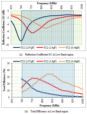 Figure 6. Passive measurement results in Low Band region
capacitance value of TC2 (at 0.48pF, 1.9pF and 2.97pF) are used to shift the Low Band resonance across the Low Band region of 700MHz to 960MHz. This shift in the Total Efficiency plot (as seen in Figure 6(b)) helps to maintain the Total Efficiency in the Low Band region at above 20%.
3.2. Mid Band Tuning (1710MHz to 2170MHz)
The Mid Band of the Main Antenna is resulting from a Slot Antenna form on the Metallic Back Cover by the Closed-end slot, as highlighted with the black-dotted line in Figure 7(a). The Tunable Capacitor TC1, which output is bridged across the Closed-end slot on the Metallic Back cover, is being used to provide Aperture Tuning to this Slot Antenna. The configuration of having the Tunable Capacitor TC1 across the Closed-end slot can be best described by the equivalent circuit as shown in Figure 7(b). Hence, by tuning the capacitance value of Tunable Capacitor TC1, the wavelength of the Slot Antenna will change accordingly, shifting the Mid Band resonance within the frequency range of 1710MHz to 2170MHz. In tuning the Mid Band of the Main Antenna, the capacitance value of both the Tunable Capacitor TC2 and TC3 on the Main Antenna PCB are kept constant at 2.97pF.
Figure 8 shows plots of the passive measurement result for the Mid Band Tuning of the Main Antenna, in Free-Space condition. Figure 8(a) is the measured Reflection Coefficient S11 of the Main Antenna and Figure 8(b) shows plots of the measured Total Efficiency of the Main Antenna in the Mid Band region. From the two plots shown in Figure 8, it can be seen that the Mid Band resonance can be made to shift across the Mid Band region of 1710MHz to 2170MHz by tuning the capacitance value of TC1 at 1.55pF, 1.9pF, 2.44pF and 2.97pF respectively. This shift in the Total Efficiency plot (as seen in Figure 8(b)) helps to maintain the Total Efficiency in the Mid Band region at above 20%.
- Slot Antenna for Mid Band Tuning
- Equivalent circuit of Tuner Board on Metallic Back Cover
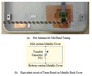 Figure 7. Mid Band Tuning of Main Antenna
- Reflection Coefficient S11 in Mid Band region
- Total Efficiency in Mid Band region
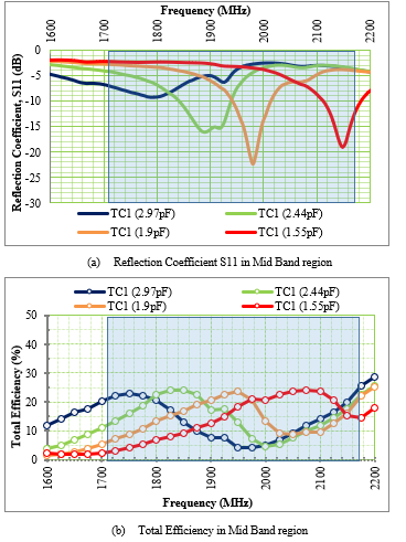 Figure 8. Passive measurement results in Mid Band region
3.3. High Band Tuning (2300MHz to 2690MHz)
In High Band Tuning of the Main Antenna, the energy from the Capacitive Feed Patch on the Bottom-section metallic cover is coupled across the Closed-end slot to the Mid-section metallic cover. Current on the Mid-section metallic cover will then flows in the direction as indicated by the red-coloured arrow to Gnd-Pin2 on the Main Antenna PCB, as shown in Figure 9 (a). This actually forms a small Loop Antenna for the High Band of the Main Antenna. Aperture Tuning is applied to this small Loop Antenna at Gnd-Pin2, via the Tunable Capacitor TC3, which equivalent circuit is as shown in Figure 9 (b). The resonance at the High Band of the Main Antenna can be made to shift within the frequency range of 2300MHz to 2690MHz by tuning the capacitance value of the Tunable Capacitor TC3 on the PCB. In tuning the High Band of the Main Antenna, the capacitance value of the Tunable Capacitor TC1 on the Metallic Back Cover and the Tunable Capacitor TC2 in the Tunable LC Resonant Circuit on the PCB are both kept constant at 2.97pF.
- Current flow for High Band Tuning
- Equivalent circuit of Aperture Tuning at Gnd-Pin2
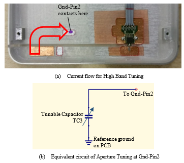 Figure 9. High Band Tuning of Main Antenna
- Reflection Coefficient S11 in High Band region
- Total Efficiency in High Band region
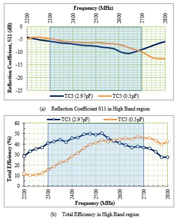 Figure 10. Passive measurement results in High Band region
Figure 10 shows plots of the passive measurement result for the High Band Tuning of the Main Antenna, in Free-Space condition. Figure 10 (a) is the measured Reflection Coefficient S11 of the Main Antenna and Figure 10 (b) shows plots of the measured Total Efficiency of the Main Antenna in the High Band region. From the two plots shown in Figure 10, it can be seen that two-different capacitance value of TC3 (0.3pF and 2.97pF) are used to shift the High Band resonance across the High Band region of 2300MHz to 2690MHz. This shift in the Total Efficiency plot (as seen in Figure 10(b)) helps to maintain the Total Efficiency in the High Band region at above 40%.
4. Mobile Phone Mockup in Active Phone Condition
In this section, the Metallic Back Cover mobile phone mockup as reported above is configured to be an active phone. Figure 11 shows a picture illustrating the Metallic Back Cover mobile phone mockup in its active phone configuration. The mockup is equipped with an in-house designed Main PCB which is used to house a Long-Term Evolution (LTE) module for conducting active Total Radiated Power (TRP) measurement in an Anechoic OTA Chamber. The Main PCB is equipped with power contact points to draw power from a mobile phone battery, to power up the LTE Module as well as the Tunable Capacitors (TC1, TC2 and TC3 mentioned above in section 2 and 3) during the active measurement.
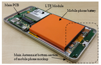 Figure 11. Mobile phone mockup in active condition
4.1. Measurement in Free-Space
The active TRP measurement in the Free-Space condition was conducted in an Anechoic OTA Chamber, for four different 3G bands and five different 4G LTE bands. These bands are WCDMA Band 1, 2, 5 and 8 in the 3G network, and FDD LTE Band 1, 4, 7, 8 and 13 in the 4G LTE network. Table 1 tabulates the active TRP measurement results of the Main Antenna, with the metallic cover mobile phone mockup in Free-Space condition. The first column in Table 1 lists the respective nine frequency bands in the 3G and 4G network. The second column displays the mid channel for each band respectively, and the third column lists the frequency (in MHz) corresponding to respective mid channel in the second column. As can be seen from the third column, this measurement covers the various frequencies which fall within the Low (700MHz to 960MHz), Mid (1710MHz to 2170MHz) and High (2300MHz to 2690MHz) Band regions of the Main Antenna. The fourth column in Table 1 lists the measured Conducted Power (in dBm) of the LTE Module, transmitting at the respective frequencies listed in the third column. And lastly, the measured Free-Space TRP (in dBm) of the Main Antenna on the Metallic Back Cover mobile phone mockup is as listed in the fifth column. From Table 1, the Conducted Power of the LTE Module is ranging from 20 to 23dBm, and the Free-Space TRP ranges from 14 to 20dBm.
Table 1. Active TRP measurement results in Free-Space
| Band | Channel | Frequency (MHz) | Conducted Power (dBm) | Free-Space TRP (dBm) |
| WCDMA Band5 | 4182 | 836.6 | 22.3 | 17.8 |
| WCDMA Band8 | 2787 | 897.6 | 22.2 | 16.7 |
| WCDMA Band2 | 9400 | 1880.0 | 22.9 | 15.1 |
| WCDMA Band1 | 9750 | 1950.0 | 22.4 | 14.1 |
| FDD LTE Band13 | 23230 | 782.0 | 22.0 | 16.9 |
| FDD LTE Band8 | 21625 | 897.5 | 21.2 | 16.6 |
| FDD LTE Band4 | 20175 | 1732.5 | 21.8 | 15.7 |
| FDD LTE Band1 | 18300 | 1950.0 | 21.7 | 13.8 |
| FDD LTE Band7 | 21100 | 2535.0 | 20.2 | 19.7 |
4.2. Measurement with Phantom Head & Hands
To study the user effect towards the Main Antenna solution on the metallic cover mobile phone mockup, the active TRP measurement was further extended to the Phantom Head & Hands configuration. Figure 12 shows an example of the setup of the Phantom Head + Right Hand (BHHR) in the talk mode configuration. In this setup, the metallic cover mobile phone mockup will be gripped by the Hand, and placed beside the Phantom Head, as according to the CTIA Test Plan [7]. Two Phantom configurations had been considered in this measurement: Phantom Head + Left Hand (BHHL) and Phantom Head + Right Hand (BHHR). This active TRP measurement of the Main Antenna, with the mobile phone mockup on the Phantom Head & Hands was conducted in an Anechoic OTA Chamber, for four different 3G bands (WCDMA Band 1, 2, 5 and 8). Table 2 tabulates the active TRP measurement results of the Main Antenna, with the mobile phone mockup on the Phantom Head & Hands (BHHL and BHHR) talk mode configuration. The first three columns in Table 2 list the frequency bands, its mid channel and the corresponding frequency in the 3G network respectively. The fourth and fifth column in Table 2 list the measured TRP (in dBm) of the Main Antenna, in the BHHL and BHHR configuration respectively. From the BHHL TRP and BHHR TRP results listed in Table2, it can be clearly seen that the left hand has a greater influence on the Main Antenna performance as compared to the right hand. This is likely due to the hand is covering the opening of the Closed-end slot on the Metallic Back Cover in the BHHL configuration. The variation in TRP between BHHL and BHHR is between 1 to 3.3dBm, with the worst case scenarios taking place at WCDMA Band 2 (1880MHz). A comparison between the Free-Space TRP (in Table 1) and BHHL TRP (in Table 2) shows a reduction in the antenna performance in the latter case with variation of between 5.9 to 9.6dBm, and the worst case scenarios taking place at WCDMA Band 8 (897.6MHz). The comparison between the Free-Space TRP and BHHR TRP also shows a reduction in the antenna performance in the latter case, with variation of between 4.6 to 8.4dBm, and the worst case scenarios taking place at WCDMA Band 5 (836.6MHz).
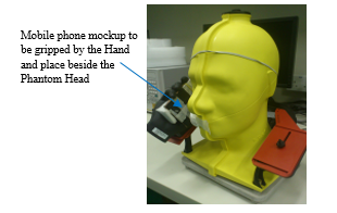 Figure 12. Phantom Head + Right Hand (BHHR) in talk mode setup
Table 2. Active TRP measurement results in BHHL and BHHR
| Band | Channel | Frequency (MHz) | BHHL TRP (dBm) | BHHR TRP (dBm) |
| WCDMA Band5 | 4182 | 836.6 | 8.3 | 9.3 |
| WCDMA Band8 | 2787 | 897.6 | 7.1 | 9.6 |
| WCDMA Band2 | 9400 | 1880.0 | 7.0 | 10.3 |
| WCDMA Band1 | 9750 | 1950.0 | 8.2 | 9.5 |
5. Conclusion
It has always been challenging in providing solution for antennas on mobile phones with metal housing. The metal housing often introduces unnecessary coupling, shielding effect towards the antennas as well as reducing the flexibility in designing the antenna. In this paper, a tunable solution has been proposed for the cellular Main Antenna of a mobile phone with metal housing in the form of metallic back cover. The proposed solution demonstrates the integration of the metal housing as part of the antenna design, along with the use of different Aperture Tuning circuitries at different parts of the Main Antenna, to allow flexible tuning of the antenna’s Low, Mid and High Band. In an attempt to study the user effect towards the Main Antenna on the metallic cover mobile phone, the measurement results suggested that the Left Hand influence on the antenna is greater as compared to the Right Hand. In the comparison between Free-Space and BHHL/BHHR condition, the antenna performance sees a reduction of less than 10dBm.
- Mark Y.C. Tan, Guan Hong Ng, Roger Tay, “A tunable LTE main antenna solution for metallic cover mobile phone”, 2017 11th European Conference on Antennas and Propagation (EuCAP), 19 – 24 March 2017. https://doi.org/10.23919/EuCAP.2017.7928219
- A. Tornatta, R. Gaddi, “Aperture tuned antennas for 3G-4G applications using MEMS digital variable capacitor”, 2013 IEEE MTT-S International Microwave Symposium Digest (IMS), 2 – 7 June 2013. https://doi.org/10.1109/MWSYM.2013.6697602
- Sameer Akhtar Shah, Liu Qianyun, “A novel approach to design an antenna aperture tuning circuit”, 2015 Asia-Pacific Microwave Conference (APMC), 6 – 9 Dec 2015. https://doi.org/10.1109/APMC.2015.7413123
- Mark Y.C. Tan, Guan Hong Ng, Roger Tay, “Tuning of LTE Main Antenna Using Flexible Tunable LC Resonant Circuitry”, 2017 11th European Conference on Antennas and Propagation (EuCAP), 19 – 24 March 2017. https://doi.org/10.23919/EuCAP.2017.7928223
- Wei-Yu Li, Chun-Yih Wu, Kin-Lu Wong and Ming-Fang Tu, “Internal small-size PIFA for LTE/GSM/UMTS operation in the mobile phone”, 2010 IEEE Antennas and Propagation Society International Symposium (APSURSI), July 2010. https://doi.org/10.1109/APS.2010.5562325
- Norakamon Wongsin, Thanakarn Suangun, Chatree Mahatthanajatuphat, Prayoot Akkaraekthalin, “A multiband fractal ring antenna fed by capacitive coupling”, 2011 8th International Conference on Electrical Engineering/Electronics, Computer, Telecommunications and Information Technology (ECTI-CON), 17 – 19 May 2011. https://doi.org/10.1109/ECTICON.2011.5947808
- “Test plan for wireless device Over-the-Air performance”, CTIA, version 3.6.2, May 2017. https://www.ctia.org/docs/default-source/certification/ctia-test-plan-for-wireless-device-over-the-air-performance-ver-3-6-2.pdf?sfvrsn=2
No related articles were found.