A New profiling and pipelining approach for HEVC Decoder on ZedBoard Platform

Adv. Sci. Technol. Eng. Syst. J. 2(6), 40–48 (2017);
 DOI: 10.25046/aj020605
New multimedia applications such as mobile video, high-quality Internet video or digital television requires high-performance encoding of video signals to meet technical constraints such as runtime, bandwidth or latency. Video coding standard h.265 HEVC (High Efficiency Video Coding) was developed by JCT-VC to replace the MPEG-2, MPEG-4 and h.264 codecs and to respond to these new functional constraints. Currently, there are several implementations of this standard. Some implementations are based on software acceleration techniques; Others, on techniques of purely hardware acceleration and some others combine the two techniques. In software implementations, several techniques are used in order to decrease the video coding and decoding time. We quote data parallelism, tasks parallelism and combined solutions. In the other hand, In order to fulfill the computational demands of the new standard, HEVC includes several coding tools that allow dividing each picture into several partitions that can be processed in parallel, without degrading neither the quality nor the bitrate. In this paper, we adapt one of these approaches, the Tile coding tool to propose a pipeline execution approach of the HEVC / h265 decoder application in its version HM Test model. This approach is based on a fine profiling by using code injection techniques supported by standard profiling tools such as Gprof and Valgrind. Profiling allowed us to divide functions into four groups according to three criteria: the first criterion is based on the minimization of communication between the different functions groups in order to have minimal intergroup communication and maximum intragroup communication. The second criterion is the load balancing between processors. The third criterion is the parallelism between functions. Experiments carried out in this paper are based on the Zedboard platform, which integrates a chip Zynq xilinx with a dual core ARM A9. We start with a purely sequential version to reach a version that use the pipeline techniques applied to the functional blocks that can run in parallel on the two processors of the experimental Platform. Results show that a gain of 30% is achieved compared to the sequential implementation.
1. Introduction
This paper is an extension of the work originally presented in [1].
In recent years, the number of applications processing digital video is steadily growing. Streaming videos, videoconferencing, web cameras, mobile video conversations are examples of digital video that require good video quality.
In addition, statistics show that by 2020 [2], Internet video streaming and downloads will increase to over 80% of all consumer Internet traffic. This growing demand for digital video processing encourages digital video coding market operators to design and develop new solutions that can meet this growing need.
Indeed, we are witnessing an increase in companies and research groups working to develop standards of video codec with better quality.
The JCT-VC (Joint Collaborative Team on Video Coding) group, formed by VCEG and MPEG, was created at the end of 2009 to create a new standard that meets the new requirements of video processing [3]. Following the work of this group, a new standard called H.265 / HEVC (High Efficiency Video Coding) was created with the aim of compressing a half-rate video from the previous H.264 / AVC standard to one Quality. This improvement in terms of efficiency is necessary to manage beyond high definition resolutions like HD, Quad-HD and Ultra-HD.
Many research groups and companies participate in standardization meetings and contribute to the growth of the standard with new algorithms. As a result, many implementations of this standard have been developed. One of these implementations is the test model software [4], which is a complete encoder and a decoder for the new algorithms.
To design video processing devices that implement standard video encoders, designers investigate several solutions. All solutions are based on improvement techniques based on software or hardware optimization approaches or a combination of both approaches.
The work undertaken in this paper is part of the LIP2 co-design flow.
In a co-design process, designers typically begin to run embedded application code on a host machine. Then, a thin profiling step is done to describe each function. This description can affect the execution time, memory size, number of calls, relationship between functions and other parameters that may be useful for the designer to make the best design decisions.
In this paper, we present a new approach to implement a pipeline solution of the HEVC H.265 application decoder based on the Zedboard platform [5]. The results show that a gain of 30% is achieved compared to the sequential implementation.
The rest of this article is organized as follows: Section 2 presents an overview of the HEVC Standard and HEVC h.265 decoders. In section 3, we present some works in relation with HEVC parallelization.
Section 4 gives a detailed description and profiling of the version of the test model of the decoder and analyses the results obtained. Section 4 shows the execution of the decoder pipeline on the Zedboard platform. Finally, Some conclusion remarks and future directions are given in Section 6.
2. Overview of the HEVC Standard
Due to the complexity of multiprocessor systems, the probability of failure is all the more important that it requires special consideration. Indeed, during a failure, a part of the application state disappears and the application may pass in an inconsistent state that prevents it from continuing normal execution.
The HEVC [5,6] is the acronym of “High Efficiency Video Coding”. This is the latest video-coding format used by JCT-VC. This standard is an improvement of the H.264 / AVC standard. It was created on January 2013 [7], when a first version was finalized. It was developed jointly by the ISO / IEC Moving Picture Experts Group (MPEG) & ITU-T Video Coding Experts Group (VCEG).
The main objective of this standard is to significantly improve video compression compared to its predecessor MPEG-4 AVC / H.264 by reducing bitrate requirements by as much as 50% compared to H.264/ AVC, with equivalent quality.
The HEVC supports all common image definitions. It also provides support for higher frame rates, up to 100, 120 or 150 frames per second.
Video coding standards have evolved mainly through the development of the well known ITU-T and ISO / IEC standards. ITU-T produced H.261 [8] and H.263 [9], ISO / IEC produced MPEG-1 [10] and MPEG-4 Visual [11], and the two organizations together produce H. 262 / MPEG -2 Video [12] and H.264 / MPEG-4 Advanced Video Coding (AVC) [13,14] standards.
The two standards that have been produced jointly have had a particularly strong impact and have found their way into a wide variety of products that become increasingly common these days. In the course of this evolution, efforts have been multiplied to increase the compression capacity and to improve other characteristics such as the robustness against data loss. These efforts take into account the capability of practical IT resources to be used in products at the time of the expected deployment of each standard.
The HEVC standard is intended to complement various objectives and to meet even stronger needs to encode videos with an efficiency more important than H.264 / MPEG -4. Indeed, there is a growing diversity of services such as ultra high definition television (UHDTV) and video with a higher dynamic range.
On the other hand, the traffic generated by video applications targeting peripherals and mobile tablets and transmission requirements for video-on-demand services impose serious challenges in current networks. An increased desire for quality and superior resolutions also occurs in mobile applications.
The HEVC standard defines the process of encoding and decoding the video. As an input, the encoder will process an uncompressed video. It performs the prediction, transformation, quantification and entropy coding processes to produce a bitstream conforming to the H.265 standard.
The decoding process is divided into four stages. The first stage is the entropy decoding for which relevant data such as reference frame indices; intra-prediction mode and coding mode are extracted. These data will be used in the following stages. The second is called reconstruction step, which contains the inverse quantization (IQ), inverse transform (IT) and a prediction process, which can be either intra-prediction or motion compensation (inter-prediction). In the third stage, a de-blocking filter DF is applied to the reconstructed frame. Finally a new filter called Sample Adaptive Offset (SAO) is applied in the fourth stage. This filter adds offset values, which are obtained by indexing a lookup table to certain sample values [14].
In HEVC, the coding structure is based on a quaternary tree representation allowing partitioning into multiple block sizes that easily adapt to the content of the frames. Three units are defined to treat each frame. First, the Coding Unit (CU) that defined the frame‘s based size on pixels. It allows sizes ranging from 8×8 to 64×64 pixels to be adapted according to the application. Second, the Prediction Unit (PU) that defines the partitioning size according to predicts type (inter and intra). Finally, the Transform Unit (TU) defines the quantification and transforms size to be applied to a prediction unit. Four levels of decomposition are possible for this TU, which take sizes ranging from 4×4 to 32×32 pixels.
Three types of coding structures are defined; ALL intra or intra-only (AI), Low Delay (LD) and Random Access (RA). In the first structure, all pictures are encoded as intra, which yields very high quality, and no delay; this mode is mainly aimed for studio usage.
In the low delay one, the first is an intra frame while the others are encoded as generalized P or B pictures (GPB). This structure is conceived for interactive real-time communication such as video conferencing or real-time uses where no delay for waiting for future frames is permitted.
Finally, the random access structure is similar to hierarchical structure and intra pictures are inserted periodically, at the rate of about one per second. It is designed to enable relatively frequent random access points in the coded video data. This coding order has an impact on latency, since it requires frame reordering: for this reason the decoder might have to wait to have decoded several frames before sending them to output. This is the most efficient mode for compression but also requires the most computational power.
Each of these three modes has a low complexity variant where some of the tools are disabled or switched into a faster version. As an example low complexity uses CAVLC instead of CABAC
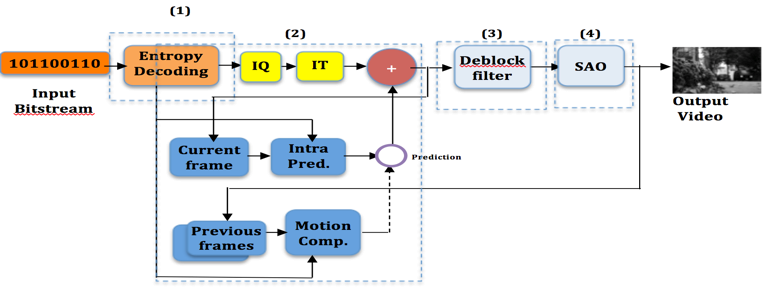 Fig.1: Functional structure of the HEVC decoder
3.Related works
HEVC includes several parallel specifications for many distributed multi-core systems. This allows division of each picture into several partitions that can be processed in parallel.
For these specifications, coarse grain communications levels are used. We cite the Group Of Pictures (GOP) level, the Slice Level, the Tile level and the wavefront parallel processing (WPP) level.
All these communication granularity has been justified by the small data dependency between processes acting on separate partition blocks.
For an embedded multiprocessor System on Chip (SoC) implementation, the communication granularity specified is not appropriate in all cases given the limited on-chip resources (memory, CPU frequency, bandwidth, …). For this, more fine grain communications granularities (CTU, TU, PU) are specified in HEVC standard based on a fine partition of a frame.
In [15], Authors carried out the analysis of parallel processing tools to understand the effectiveness of achieving the purpose for which they are targeted. In [16], an optimized method for MV-HEVC is proposed. It uses multi-threading and SIMD instructions implementation on ARM processors. The proposed method of MV-HEVC showed improvement in terms of processing speed on advanced RISC multi-core processors mobile platforms (ARM). In [17], Authors used the Wavefront Parallel Processing (WPP) coding and implemented it on multi- and many-core processors. The implemented approach is named Overlapped Wavefront (OWF), an extension of WPP tool that allows processing multiple picture partitions as well as multiple pictures in parallel with minimal compression losses. Results of her experimentations show that exploiting more parallelism by increasing the number of cores can improve the energy efficiency measured in terms of Joules per frame substantially. [18] discussed various methods in which the throughput of the video codec has been improved including at the low level in the CABAC entropy coder, at the high level with tiles, and at the encoder with parallel merge/skip tool. In [19], many optimizations are proposed to achieve HEVC real-time decoding on a mobile processor. These code optimizations include the adoption of single-instruction multiple-data (SIMD). An important speedup is accomplished with multiple threads assigned each one to a picture to be decoded. However, in the proposed solution, the SAO filter has not been implemented and optimized. Further, for the AI configuration, no additional speedup is achieved since no CPU resources are available anymore to decode a picture. In [20], a hybrid parallel decoding strategy for HEVC is presented. It combines task and data parallelism without any constraint or coding tools. The proposed approach aims to balance execution time of different stages, especially with SSE (Streaming SIMD Extensions) optimization. Another parallelism approach based on entropy slices is presented in [21]. This approach is not based on many slices because it can reduce the coding efficiency. It assigns one thread per LCU block to parallelize the HEVC decoder. Moreover, these threads are synchronized using the Ring-Line Strategy to maintain the wave front dependencies. This solution is great for high resolutions; however, it’s not the same for others.
-
Profiling of Test Model HEVC Decoder
In the specification and modelling phase of a co-design flow, the complete embedded system is written in a high level language such as C, C++, Java, Matlab and then the software is functionally verified. It will then be simulated on a host machine in order to understand its behaviour and measure the runtime performance of the program and eventually return feedback and performance statistics to the designer
This specification is an input to the profiling step, which consists in understanding the behaviour of the system in the various execution cases in order to deduce a clear representation of the various functions that represent it.
The behaviour of the system can be understood and mastered by following a parametric analysis of its execution in the different configurations and situations that the system is subject to.
This analysis can only be undertaken after having completed a detailed description of different functions of the system. The description can include the execution time of each function, its sizes, call graphs, dependencies between them and other information that can help designers to make the best decisions and technical choices. This process of identification and description is called profiling.
Once the profiling is done, designers can test the system with several configurations and estimate its performance parameters.
Several works dealing with performance estimation of embedded systems have been realized. In the case of the HEVC codec, performance estimation aims to test the ability of codecs to process video for real-time applications and to support new resolutions (HD, UHD, Full HD, 4k, 8k) and to measure footprint and the space occupied by the hardware components that make up the device.
In the work carried out by [22], a complete profiling of the encoder was carried out. The aim of this work is to present the different functions of the encoder, their execution times and the types of operations carried out in order to deduce the functions that are candidates for a hardware migration. The results are presented in terms of types of assembly level instructions in each encoder function. In [23], the authors propose a hybrid parallel decoding strategy for HEVC, which combines task level parallelism and data level parallelism. In [24], the authors use a performance estimation analysis to prove a power model based on bit derivations that estimates the energy required to decode a given HEVC coded bitstream. In [25], authors proposed a method to improve H.265/HEVC encoding performance for 8K UHDTV moving pictures by detecting amount or complexity of object motions.
4.1. Functions of the Test Model
HEVC HM Test Model is an open source project under BSD license. It is intended for the implementation of an efficient C++ HEVC decoder. The version used in this work was released from [4] and it is compliant with most of the HEVC standard. The code of the application is composed of C++ classes, and the main classes and functions are listed in the table 1.
The graph below (Figure 2) shows the most important classes in the decoding process and their associated functions. We note that the most significant classes are TComDataCU, TComTrQuant and TComSlice. The TComDataCU class represents the declaration of the CU data structure. The TComTrQuant class includes inverse transformation and inverse quantization, and the TComSlice class includes the decoder decompression process.
The optimization of the codes of the functions making up these classes can have a positive impact on the execution time and the footprint of the decoder.
As DecodeCTU, DecompressCtu called recursive function xDecompressCU which, in turn, decompresses each CU with the adequate prediction mode. When all CTUs in a frame are processed, the loop ends and the decoder performs both DF and SAO filters to correct artefacts.
Table 1: Main classes and principal functions of test model decoder
| Main Classes | Principal functions | Size of code
(Ko) |
| TDecGop | FilterPicture
decompressSlice |
8 |
| TAppDecCfg | parseCfg | 9 |
| TAppDecTop | Decode x WriteOutput |
21 |
| TDecEntropy | decodePredInfo
decodePUWise decodeInterDirPU |
28 |
| TdecTop | Decode Executeloopfilter | 32 |
| TComLoopFilter | xDeblockCU
LoopFilterPic |
35 |
| TDecCU | decompressCtu decodeCtu xdecodeCU xcompressCU xReconInter xReconIntraQT |
44
|
| TComSlice | decompressSlice | 126 |
| TComTrQuant | partialBufferflyInverse32
partialBufferflyInverse16 partialBufferflyInverse8 xDeQuant |
135 |
| TComDataCU | initCu
copySubCu |
140 |
As shown in the diagram in Fig. 3, the process of decoding a frame is done by calling the DecompressCTU function of the TDecSlice class. This function executes a read loop of all CTUs in the current frame. Each CTU is decoded through the DecodeCtu function of the TDecCu class. The XdecodeCu function of the same class, recursively performs the decoding of all CUs in the same CTU. When decoding a CTU, the TDecSlice makes a second call to the DecompressCTU function of the TDecCu class. Like DecodeCTU, DecompressCtu call the recursive function xDecompressCU, which, in turn, decompresses each CU with the proper prediction mode. When all CTUs in a frame are processed, the loop ends and the decoder perform DF and SAO filters to correct the artefacts.
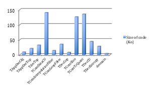 Fig.2: Main functions of Test Model Decoder
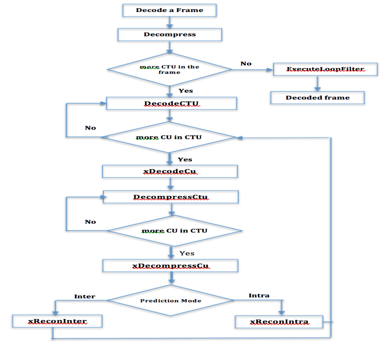 Fig.3: Frame decode Diagram of HM version
4.2. Call Graph functions of HM HEVC Decoder
Our goal in this step is to check the behaviour of the decoder described above, and to evaluate the performance of its various components in detail.
To achieve the profiling operation, we made use of profiling techniques based on code injection and also the use of tools such as gprof [26, 27] and Valgrind [28]. Gprof provides a flat profiling to give the execution time of each function of the decoder and also the number of times this function is called. Gprof can give us as a result, the call graph. This indicates for each function code, the number of times it was called, either by other functions or by itself. This information shows the relationships between the different functions and can be used to optimize certain code paths. Roughly, the results of profiling the performance generated by GProf revealed a runtime complexity of balance in terms of computing time in the functions Motion Compensation (36%) and ExecuteLoofilters of (16.7%).
Valgrind is a GPL licensed programming tool that can be used for profiling under the Linux operating system. It includes several tools, one of which is Callgrind. We used Callgrind to obtain the exact number of operations that were performed while decoding an entire video sequence. The results are separated in terms of classes, and in every class in terms of functions.
The resulting graph shows for each function, the execution time as a percentage of the total execution time (Valingring) and the functions to which they appealed. Normally, the graph shows that the most time-consuming functions are Motion Compensation and ExecuteLoofilters.
The aim of the profiling step is to understand the behaviour of the decoder described above and to evaluate the performance of its various components in detail.
To do so, we used profiling tools such as Gprof and Valgrind. These tools allow us to present the call graphs of the different functions and their execution times, and thus the state of the stack used. In order to have a complete profiling which includes the execution sequences in the different execution scenarios and configurations, a manual injection of code has been realized into significant functions.
The Gprof tool can give as a result, the call graph. This indicates for each function, the number of times it was called. This information shows the relationships between the different functions and can be used to optimize some code paths.
The profiling results generated by GProf revealed a computational complexity in terms of execution time in Motion Compensation (36%) and ExecuteLoofilters (16.7%) functions.
Valgrind is a GPL licensed tool. It includes several tools, one of which is Callgrind. We used Callgrind to get the exact number of operations performed when decoding a complete video sequence. The results are separated in terms of classes and in each class in terms of functions.
The resulting graph shows, for each function, the execution time as a percentage of the total execution time and the functions to which they appealed.
The graph shows that the most time-consuming functions are Motion Compensation and ExecuteLoofilters.
4.3. Profiling and functions Execution trace
As explained above, in order to determine the sequence of execution of the various functions of the decoder and the number of calls, a combination of code injection (manual code injection) and sampling profiling (using tools such as valgrind , Gprof, …) has been made. The code injection in each function of the decoder has allowed us to locate called and calling functions. This also helps us to know the execution sequential order of different functions.
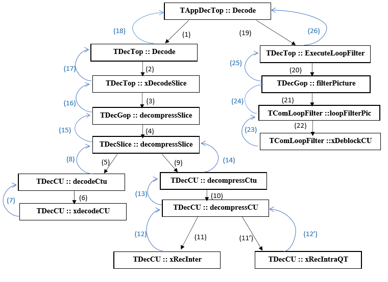 Fig.4: Functions execution Sequences
Values in parentheses indicate the execution order of decoder’s functions.
The distribution of functions into groups is mainly based on three criteria: The first is to minimize communication between different groups of functions in order to have minimal inter-group communication and maximum intra-group communication. The second criterion is load balancing between the processors. Indeed, the target platform (Zedboard) is equipped with the two ARM V9 processors. To ensure optimal utilization of two processors, we must balance the charge of activity between the two cores. The third criterion is the execution parallelism. Indeed, we must ensure maximum parallel execution to minimize the average processing time of images.
Taking into account all the criteria, we came to the distribution of assigning the group functions 1, 2 and 4 to processor 0 (proc0) and functions of the group 3 to processor 1 (Proc1).
The calculations we have developed suggested the division mentioned above with the following performance data:
■ CPU.0:
Group 1: (1) (2) (3) (4) (15) (16) (17) (18) = 24.46%
Group 2: (5) (6) (7) (8) = 6.85%
Group 4: (19) (20) (21) (22) (23) (24) (25) (26) = 16.70%
Total activity time = 48.01%
■ CPU.1
Group 3: (9)(10)(11)(11’) (12)(12’)(13)(14)= 51.95%
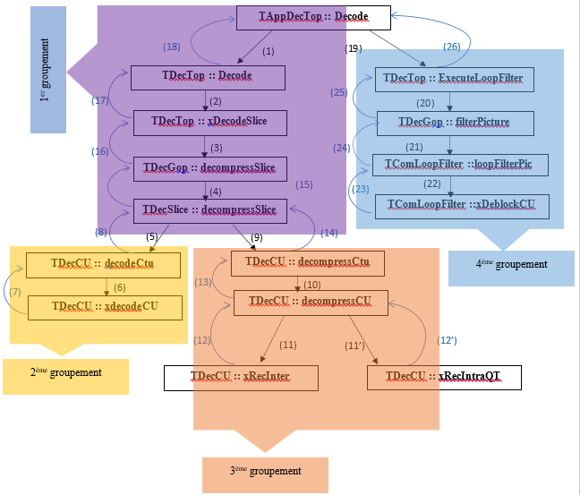 Fig.5:Grouping decoder functions
According to profiling procedure, we can divide the code on four main parts (Figure 4). The first contains the configurations functions. The second group represents the entropy decoding functions (decodeCTU and xdecodeCU). The third group is the reconstruction. Finally, the HEVC filters are grouped. We analyse their decoder’s execution time in order to know its behaviour at runtime.
5. Experimental results
5.1. Test sequences
As an effort to carry out a good evaluation of the standard, the JCT-VC developed a document with some reference sequences and the codec configuration, which should be used with each one [29]. The sequences are divided into 6 groups (Classes) based on their temporal dynamics, frame rate, bit depth, resolution, and texture characteristics
A subset of six video sequences was selected from this list. These six video sequences were selected from three classes, such that two sequences from each class, namely Class A, Class C, Class F. Detailed descriptions of the sequences are given in Table II.
Table 2: Bitstreams used in the experimentations
| Resolution
(Sequence class) |
Name |
Frame rate | Frame number |
| 2560×1600
(Class A) |
PeopleOnStreet |
30 |
150 |
| Traffic |
30 |
300 |
|
| 832×480
(Class C) |
BQMall |
60 |
600 |
| PartyScene | 30 | 500 | |
| 1024×768
(Class F) |
ChinaSpeed | 50 | 500 |
| Slideediting | 30 | 300 |
5.2. Zedboard Platform
Zedboard platform [30] (table III) is an evaluation platform based on a Zynq-7000 family [31]. It contains on the same chip two components. A dual-core ARM Cortex MPCore based on a high-performance processing system (PS) that can be used under Linux operating system or in a standalone mode and an advanced programmable logic (PL) from the Xilinx 7th family that can be used to hold hardware accelerators in multiple areas.
The two parts (PS and PL) interact between them by using different interfaces and other signals through over 3,000 connections [32]. Available four 32/64-bit high-performance (HP) Advanced eXtensible Interfaces (AXI) and a 64-bit AXI Accelerator Coherency.
Table 3: Zedboard technical specifications
| Component | Characteristics |
| Processeur ZYNQ-7020 AP SOC XC7Z020-7CLG484CES | 2 ARM Cortex A9 cores at 667 MHz |
| Memory | 512 MB DDR3, 256 MB Quad-SPI
Flash et SD Card |
| Communication | 10/100/1000 Ethernet, USB OTG et
USB UART |
| Extension | FMC (Low Pin Count) et 5 Pmod headers (2*6) |
| Display | HDMI output, VGA output et
128*32 OLED |
| Input / Output | 8 switches, 7 push butons et 8
leds |
| Current and Voltage | 3.0 A (Max) et 12V DC input |
| Certification | CE and RoHS certifier |
In our experimentations, we have configured and compiled a custom Linux kernel downloaded from the official Linux kernel from Xilinx [31].
5.3. Pipeline execution approach
Since ZedBoard is based on Zynq chip that has dual cores, it is possible to distribute functions between the two cores.
Because of strict sequentially that we have seen in the functions execution of the HEVC decoder (HM Test Model version), the two processors will necessarily be in mutual exclusion of activity. To create parallel activity, we can transform the sequential video processing by a “pipelined” treatment.
If we refer to the grouping of functions explained above, we can consider that video sequence processing goes through four stages:
Stage 0: Download to a frame buffer (FB) the frame to be processed. This step corresponds to transition (1) in the graph (Fig. 5)
Stage 1: Decoding of the frame, corresponding to transitions (2, 3, 4, 5, 6, 7, 8). This stage corresponds to the Entropy decode process.
Stage 2: Decompression, corresponding to transitions (9, 10, 11-11 ‘, 12-12’, 13, 14). This stage corresponds to the reconstruction process (that contains Inverse Transform, Inverse Quantification, Inter- prediction and Intra-prediction).
Stage 3: Filtering, which corresponds to transitions (15, 16, 17, 18, 19, 20, 21, 22, 23, 24, 25, 26). This stage corresponds to the Loop Filter process
A parametric analysis of the application has enabled to deduce that the overall execution time of Stages 0, 1 and 3 is approximately equivalent to the execution time of Stage 2. Therefore, we can affect stages 0, 1 and 3 in the first PROC0 processor and Stage 2 to the second processor PROC1.
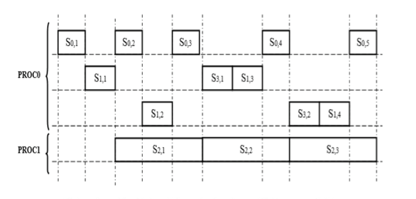 Fig.6: Pipeline execution based on dual cores Processor
Si,j represents the execution sequence of stage i applied to the frame number j. The first three rows reflect the sequencing of stage Si,j on the same processor PROC0:
Process P0, P1 and P2 support respectively the first, second and the third row.
The fourth row reflects the execution sequence of stage2 of the processor PROC1 applied to successive frames. A process P3 supports it.
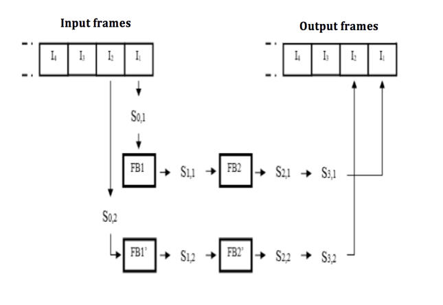 Fig.7: Sequence Process on two processors (cores)
Results obtained for the RA, AI and LD configurations are presentaed in tables IV, V and VI..
Table 4: Results for AI configuration
| Class | Sequence | Frames Number | QP | Sequential | Pipelined |
| Time
(ms) |
Time
(ms) |
||||
| A | People On Street | 150 | 22 | 594.28 | 386.28 |
| 32 | 454.59 | 295.49 | |||
| Traffic | 150 | 22 | 610.68 | 396.94 | |
| 32 | 432.75 | 281.29 | |||
| Average execution time | 523.075 | 340 | |||
| Gain | 35% | ||||
| C | Party Scene | 500 | 22 | 307.41 | 218.26 |
| 32 | 219.16 | 155.61 | |||
| BQ Mall | 600 | 22 | 259.30 | 184.10 | |
| 32 | 191.85 | 136.21 | |||
| Average execution time | 244.43 | 173.54 | |||
| Gain | 29% | ||||
| F | China Speed | 500 | 22 | 382.39 | 287.68 |
| 32 | 295.93 | 207.15 | |||
| Slide Editing | 300 | 22 | 279.75 | 199.83 | |
| 32 | 242.71 | 169.9 | |||
| Average execution time | 300.19 | 210.14 | |||
| Gain | 28% | ||||
Table 5: Results for RA configuration
| Class | Sequence | Frames Number | QP | Sequential | Pipelined |
| Time
(ms) |
Time
(ms) |
||||
| A | People On Street | 150 | 22 | 409.51 | 274.37 |
| 32 | 256.97 | 172.17 | |||
| Traffic | 150 | 22 | 293.26 | 196.48 | |
| 32 | 179.19 | 120.06 | |||
| Average execution time | 284.77 | 190.77 | |||
| Gain | 33% | ||||
| C | Party Scene | 500 | 22 | 153.41 | 107.38 |
| 32 | 89.64 | 62.75 | |||
| BQ Mall | 600 | 22 | 131.76 | 93.55 | |
| 32 | 84.08 | 59.70 | |||
| Average execution time | 114.72 | 80.84 | |||
| Gain | 29.5% | ||||
| F | China Speed | 500 | 22 | 216.84 | 156.12 |
| 32 | 140.75 | 101.34 | |||
| Slide Editing | 300 | 22 | 56.93 | 38.14 | |
| 32 | 50.25 | 33.67 | |||
| Average execution time | 116.19 | 82.31 | |||
| Gain | 29.15% | ||||
Table 6: Results for LD configuration
| Class | Sequence | Frames Number | QP | Sequential | Pipelined |
| Time
(ms) |
Time
(ms) |
||||
| A | People On Street | 150 | 22 | 446.65 | 294.79 |
| 32 | 266.68 | 176.01 | |||
| Traffic | 150 | 22 | 310.86 | 220.71 | |
| 32 | 164.25 | 116.62 | |||
| Average execution time | 297.11 | 202.03 | |||
| Gain | 32% | ||||
| C | Party Scene | 500 | 22 | 176.65 | 125.42 |
| 32 | 91.99 | 60.71 | |||
| BQ Mall | 600 | 22 | 142.03 | 99.42 | |
| 32 | 85.04 | 56.13 | |||
| Average execution time | 123.9275 | 85.42 | |||
| Gain | 31% | ||||
| F | China Speed | 500 | 22 | 217.94 | 155.84 |
| 32 | 143.83 | 99.93 | |||
| Slide Editing | 300 | 22 | 45.43 | 35.35 | |
| 32 | 41.39 | 27.85 | |||
| Average execution time | 112.14 | 74.01 | |||
| Gain | 28.89% | ||||
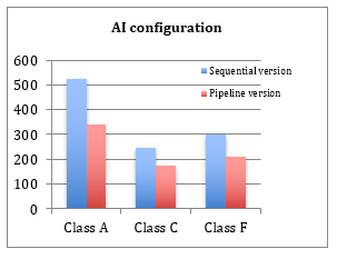 Fig.8: Execution time gain (AI configuration)
The experimental tests use reference sequences for the three configurations (AI, RA and LD) and with different quantification parameters (QPs). For the different configurations, results show a considerable gain compared to the sequential version (around 30%). We also note that class A frames have more processing time than the other classes (C and F) with a slightly more significant gain. This is logical since the resolution in this class is more important than for the other classes.
6. Conclusion
The objective of this article was to study the behaviour of the HEVC decoder represented by the reference application Test Model (HM). This study permitted us to discover the different functions of the decoder, their size, the call graphs, the percentage of CPU utilization and the number of instructions for each function.
Moreover, we have identified the most consuming functions in terms of CPU execution time and memory size, and then we have represented the execution trace of the functions by the use of an injection code technics. All these profiling results allowed us to divide the functions into groups. Once the regrouping is done, we proposed a parallelism approach based on the pipeline principle in order to run the application on the two cores of the Zedboard Platform. The experimental results found show an acceleration of about 30% compared to the sequential version.
Other technics can be added to improve this approach such as the increase of the number of processors or the implementation of hardware accelerators in the PL side.
- H. Smei, K. Smiri, A. Jemai, “Pipelining the HEVC Decoder on ZedBoard Plateform”, in 11th International Design & Test Symposium, IDT 2016, Hammamet, Tunisia, December 18-20, 2016. IEEE 2016, ISBN 978-1-5090-4900-4(IDT 2016).
- Cisco, Visual Networking Index (VNI): Forecast and Methodology, 2015-2020.
- JCT-VC – Joint Collaborative Team on Video Coding – [Online]:http://www.itu.int/en/ITU-T/studygroups/2013-2016/16/Pages/video/jctvc.aspx
- BSD Licence HEVC decoder (HM), Reference web site : [Online]:https://hevc.hhi.fraunhofer.de, code available Online at https://github.com/bbc/vc2-reference. Accessed, September 2016
- Bingjie Han , Ronggang Wang, Zhenyu Wang, Shengfu Dong, Wenmin Wang, Wen Gao, “HEVC decoder acceleration on multi-core x86 platform” IEEE International Conference on Acoustic, Speech and Signal Processing (ICASSP), 2014.
- D. Marpe and T. Wiegand, J. Sullivan, Microsoft Corporation, IEEE Communications Magazine. August 2006.
- Article about HEVC – [Online]:http://en.wikipedia.org/wiki/High_Efficiency_Video_Coding
- Video Codec for Audiovisual Services at px64 kbit/s, ITU-T Rec. H.261, version 1: Nov. 1990, version 2: Mar. 1993.
- Video Coding for Low Bit Rate Communication, ITU-T Rec. H.263, Nov. 1995 (and subsequent editions).
- Coding of Moving Pictures and Associated Audio for Digital Storage Media at up to About 1.5 Mbit/s—Part 2: Video, ISO/IEC 11172-2 (MPEG-1), ISO/IEC JTC 1, 1993.
- Coding of Audio-Visual Objects—Part 2: Visual, ISO/IEC 14496-2 (MPEG-4 Visual version 1), ISO/IEC JTC 1, Apr. 1999 (and subsequent editions).
- Generic Coding of Moving Pictures and Associated Audio Information— Part 2: Video, ITU-T Rec. H.262 and ISO/IEC 13818-2 (MPEG 2 Video), ITU-T and ISO/IEC JTC 1, Nov. 1994.
- Advanced Video Coding for Generic Audio-Visual Services, ITU-T Rec. H.264 and ISO/IEC 14496-10 (AVC), ITU-T and ISO/IEC JTC 1, May 2003 (and subsequent editions).
- H.Krichene Zrida, A.Jemai, A.C.Ammari, M.Abid, “High Level H.264/AVC Video Encoder Parallelization for Multiprocessor Implementation”, Date’09, International Conference on Design, automation &Test. Nice, France.
- P. GB, P. NS and R. Adireddy. “Analysis of HEVC/H265 Parallel Coding Tools”. PathPartner Technology consulting Pvt. Ltd. White Paper. (2014).
- W. Liu, J. Li and Y. B. Cho. “A novel architecture for parallel multi-view HEVC decoder on mobile device”. Journal on Image and Video Processing (2017).
- C. Ching, M. Alvarez-Mesa, J. L. Ben Juurlink and T. Schierl. “Parallel HEVC Decoding on Multi- and Many-core Architectures. A Power and Performance Analysis”. J Sign Process Syst (2013).
- M. Zhou, V. Sze and M. Budagavi. “Parallel Tools in HEVC for High-Throughput Processing”. Applications of Digital Image Processing XXXV, Vol. 8499, 849910, (2014).
- B. Bross and al. “HEVC Real-time Decoding”, SPIE Proceedings Vol. 8856: Applications of Digital Image Processing XXXVI, (2013).
- B. Han and al. “HEVC Decoder acceleration multi-core X86 plateform”, IEEE International Conference on Acoustics, Speech and Signal Processing (ICASSP), ( 2014).
- M. Alvarez-Mesa and al. “Parallel video decoding in the emerging HEVC standard”, 2012 IEEE International Conference on Acoustics, Speech and Signal Processing (ICASSP), (2012).
- F. Saab, I.H. Elhajj, A. Kayssi and A. Chehab, “ Profiling of HEVC encoder”, Article in Electronics Letters, July 2014.
- B.Han, R.Wang, Z.Wang, S.Dong, W.Wang and W.Gao, “HEVC Decoder Acceleration On Multi-Core X86 Platform”, IEEE International Conference on Acoustic, Speech and Signal Processing (ICASSP), 2014.
- C.Herglotz, D.Springer, M.Reichenbach, B.Stabernack, and A.Kaup, “Modeling the Energy Consumption of the HEVC Decoding Process”, DOI 10.1109/TCSVT.2016.2598705, IEEE, 2016.
- R.Harada, Y.Matsuo And J.Katto, “Improvement Of H.265/HEVC Encoding For 8K UHDTV By Detecting Motion Complexity”, IEEE International Conference on Consumer Electronics (ICCE), 2016.
- Gprof web Site. https://sourceware.org/binutils/docs/gprof/
- Gprof tutorial. [Online]:https://www.gadgetdaily.xyz/apply-gradual-transition-effects-to-page-elements/
- Valgrind Web site. [Online]:http://valgrind.org/.
- F. Bossen, “Common HM test conditions and software reference configurations,” in 12th Meeting: Joint Collaborative Team on Video Coding (JCT-VC) of ITU-T SG16 WP3 and ISO/IEC JTC 1/SC 29/WG 11, Geneva, 2013, document JCTVC-L1100.
- Zedboard Plateform web site. www.zedboard.org. Accessed, September 2016
- Xilinx, Inc. (2016). Zynq-7000 All Programmable SoC Technical Reference Manual. http:// www.xilinx.com/support/documentation/user_ guides/ug585-Zynq-7000-TRM.pdf.
- Linux kernel from Xilinx. [Online]:https://github.com/Xilinx/linux-xlnx