A Review of Anti- Podal Vivaldi Antenna Operating in Cellular Mobile Communications
A Review of Anti- Podal Vivaldi Antenna Operating in Cellular Mobile Communications
Volume 2, Issue 4, Page No 204-208, 2017
Author’s Name: Asim Alkhaibaria)
View Affiliations
University of Umm Al-qura, Mecca, Saudi Arabia
a)Author to whom correspondence should be addressed. E-mail: asem1983@hotmail.com
Adv. Sci. Technol. Eng. Syst. J. 2(4), 204-208 (2017); ![]() DOI: 10.25046/aj020427
DOI: 10.25046/aj020427
Keywords: Ultra Wideband, Worldwide interoperability for- microwave access, Long term evolution, Antipodal Vivaldi antenna, Long Term Evolution Advanced Wireless-fidelity, Worldwide Interoperability for- Microwave access, Global system for mobile, Voltage Standing Wave Ratio Return Loss, Perfect Electric Conductor, Computer Simulation Technology

Export Citations
The antenna proposed is a new geomantic structure of Ultra-Wideband (UWB) Anti- Podal Vivaldi antenna (AVA). It remarkably offers an attractive performance over the bands of cellular networks. However, its benefits are not limited only in particular applications, whereas radar imaging, mining detection, the biomedical science in the heating of brain cancer tumor and treatment, and the wireless communication are considered as the main applications suitable for utilization. Therefore, the focus on this paper is to spot the light illuminating into the cellular communications network Systems. On the other hands, several characteristics of Vivaldi antenna have been provided such as the gain, return loss, Voltage Standing Wave Ratio (VSWR), current distribution and E- fields. Finally, the results illustrate the capability and feasibility of the designed antenna.
Received: 26 October 2017, Accepted: 22 November 2017, Published Online: 10 December 2017
1. Introduction
Vivaldi antenna has been classified from the most attractive antennas in the fabrication, design and applications[1, 2, 3]. This is simply because of a wide range of numerous benefits emerged in the industrial developments. To begin with, it is a small size of antenna and the dimensions can be controlled from several parameters to operate over a wider bandwidth [2, 4]. The antenna also can be capable in optimization from the physical structure change side as well as the parameter change by using CST Simulation. Thus, it helps the end users an alternative solution in the industrial projects. An example of its valuable applications is that it can contribute in cellular networks Generations [1] as its compatibility in the technical performance and physical structure are a place of commercial utilization. It can also offer several applications in UWB communication systems [2]. Moreover, the gain obtained from the design provides with an indoor coverage area suitable in the required cellular networks generations with end fire characteristics and a strong radiation directivity [5]. For instance, the commercial buildings consist of several floors and offices that need a unique coverage and independent wireless network access. Therefore, the technical specifications results in a customer satisfaction, if the operators exploit this kind of antenna in the business. On the other hands, several numerous steps have been applied to the physical structure of antenna for the sake of characteristics improvement such as adding slots or notches on the patch layer [6]. Thus, Vivaldi antenna confidentially will be able to deal with more directive gain and higher data rates in the wireless networks [1, 6] as Bluetooth, wireless cellular networks supporting the military demands, Wireless Fidelity (WIFI), Worldwide Interoperability for Microwave Access (WIMAX), Global System for Mobile (GSM), Universal Mobile for Telecommunications System (UMTS), Long Term Evolution (LTE), Long Term Evolution – Advanced (LTE-A) without any issues from the antenna side. AVA applications, however, are not limited to the industrial applications, but also expanded to the medical applications such as in treating brain and neck cancers [7].
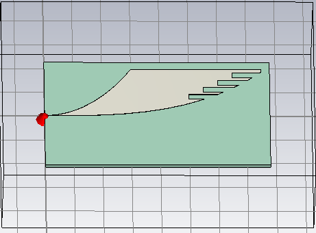 Figure 1: AVA geometric structure of proposed antenna
2. Antenna Geometry and Structure of Design
AVA is a planner antenna with UWB and linear polarizations [1, 4, 7]. The proposed antenna in this paper is illustrated in figure 1 showing a new shape. The power radiation, formation and creation of pattern radiations are a playground of technology in which particular operating frequencies offer different behavior better than others. Several sources can be used to feed the antenna and satisfy the matching and the transition requirements, whereby determining maximum bandwidth along with the operational frequencies. The designed antenna consists of a specific substrate material RF- 4 (Free Loss) and constant parameters as Epsilon (4.3) and Mute (1) with an overall dimension which is: 78mm x43mmx1.6mm. It is fed directly by discrete port. In addition, it has two exponential tapered layers as conductors with .07mm thickness and its material is made from Perfect Electric Conductor (PEC). The first one is stacked on the top of substrate fed via discrete port and the another one is printed on the bottom of substrate as a mirror with increased aperture acting as a ground plane. The parallel lines of the printed curves on the top are called stripline, where it has a balanced and fixed impedance allowing to transition process deliver more radiated power to the radiation curves, which defines the maximum wavelength between the inner curve edges acting as a horn antenna. The antenna, however, is notched with parallel slots for the sake of improving the performance such as the current distributions, radiation pattern, directivity, the gain and reducing return loss.
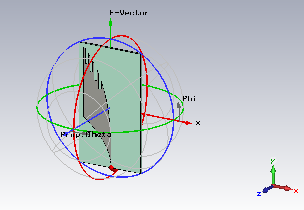 Figure 2: AVA angle and direction of radiation pattern
The formulas shown “(1)” and “(2)” describe how the layers are designed [1] on the substrate as follow:
+C1 (1)
+X2 (2)
A1=98.6, A2=100, b1=200 , b2=400 , inner=75mm, outer=30mm, Height=1.6mm, C1=-99.5mm, C2=-101mm, where:
- A1 and A2 represent as the scaling factor which is considered from the most important parameters to fix the geometric structure of antenna, so any poor adjustment of this factor causes a geometric change of the antenna and distortion issue as a consequence of the characteristics degradation.
- The outer and inner values act such as the counter of antenna heights
- b1 and b2 refer to the exponential opening rate.
- X1 and X2 refer to the displacement as an offset.
The dimension of antenna was designed and optimized in order to operate from the lower frequencies around 1GHz based on this formula:
Where, C is the speed of light, is the permittivity of substrate material and L is the maximum aperture length of antenna.
However, the designed antenna consists from three parts so the first one is the radiator curves representing the exponential curves inside the antenna, the second part is the directivity curves which are the outer curves and the last part is the matching line of antenna connecting to the source. Consequently, the methodology adopted of this designed antenna is that the microwave frequencies propagate directly towards the flare edges with a proper characteristic of radiation patterns different from each operating frequency and fixed over a graded physical structure at the edge, so that it forms a range of wider bandwidth as and the outer curves are responsible in controlling the antenna beam and the radiation patterns, whether it provides with a wider range of coverage and suitable gain or not, whereas the parallel lines are responsible for matching the impedance and allowing the signals to pass over the graded inner curve as a results of electromagnetic frequencies.
3. Results and Discussions
AVA with a new shape modeled has been designed using CST. The performance illustrates its capability to be strongly utilized in a closed area such as indoor coverage solutions and in a shorter distance such as in Bluetooth and WIFI wireless networks or any kind of cellular networks wireless communications in handing calls or data like handover. The Return loss (S11) as shown in figure. 3 clarifies a positive impression which is less than -10dB with optimum performance over UWB starting from 1GHz to 10GHz. Moreover, the gain showed a significant increase over all UMTS and GSM between 1-2 GHz, then it slightly decreased with an acceptable level from 2-5GHz, which is the area offered of WIFI, WIMAX and Bluetooth technologies as shown in the figure 4. In addition, there was a steady state of VSWR over the bandwidth, which proves the compatibility of the antenna, about 1.5:1 as illustrated in the figure 5.
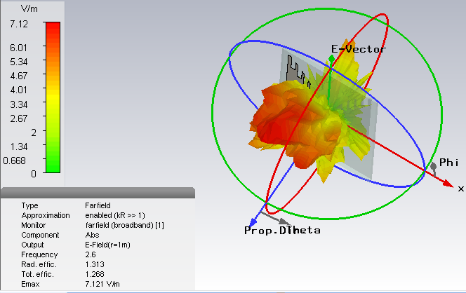
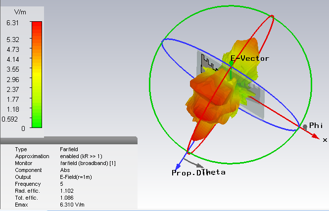
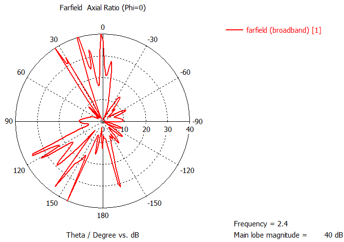
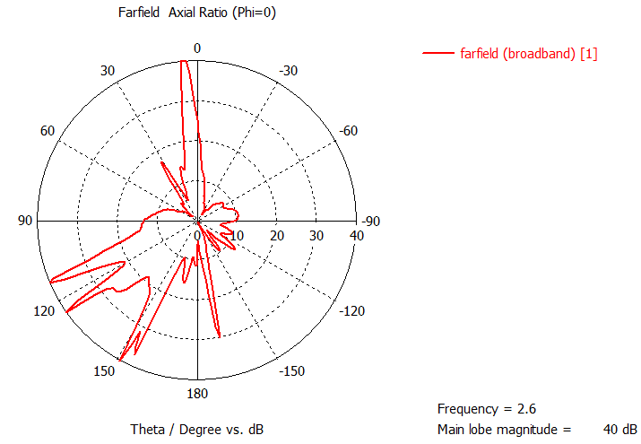
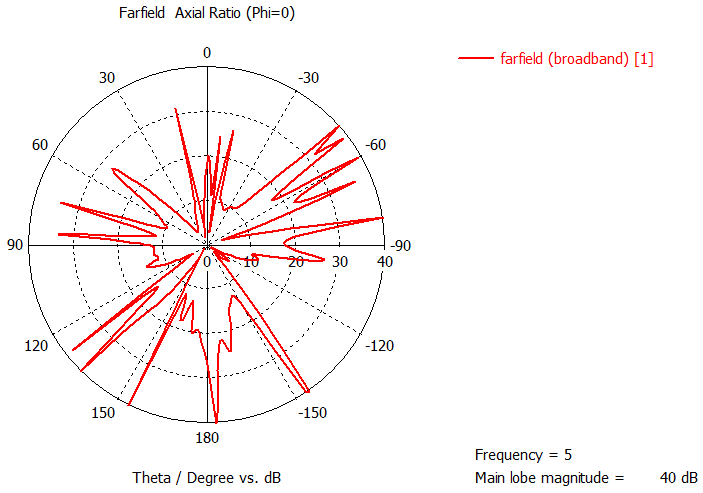
The Electric field radiation and the radiation patterns at 1GHz, 2GHz, 2.4GHz, 2.6GHz, and 5GHz respectively are presented in figure. 6 and figure.7. It demonstrates that each frequency has specific characteristics in coverage, whether it is wider or more directional at particular beam-width measured in degrees. The more wider coverage with suitable gain, the best it works in close or indoor coverage solutions such as commercial buildings, rooms, offices. However, the carrier frequencies that have a very narrow beam-width can be resolved by adding a new antenna to get a reasonable coverage and radio frequency scattered or diffracted from the edges of closed buildings.
On comparisons with electric fields radiations modeling, the structured antenna as shown in figures 6 (a,b,c,d and e) illustrates that it has a higher current distribution at1GHz rather than the others frequencies as this phenomenon is referred to electromagnetic fields penetration impact in the materials, media with surroundings reducing radio frequencies propagation and the nature of electromagnetic spectrum wavelength. Thus, the higher frequencies are susceptible of modular interactions with some particular materials as a result of energy absorption dependent on the type of material.
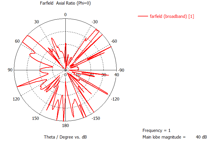
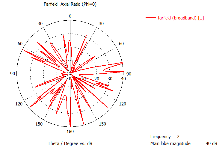
On the other hands, the figure 7 (a,b,c,d and e) provides the distribution of radiation pattern prediction of the geometric model at several frequencies. Indeed, the radiation pattern is considered one of the most important factors in determining the coverage prediction at any place. In comparison, it seems that 1GHz and 5GHz showed a wider coverage, whereas the lowest coverage were at 2.4GHz and 2.6 GHz.
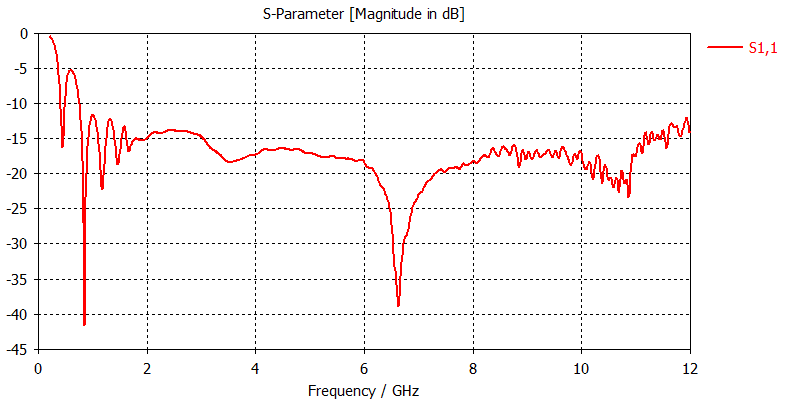 Figure 3: Return loss over frequency
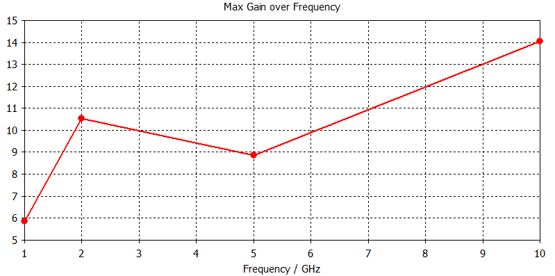 Figure 4: Antenna gain over frequency
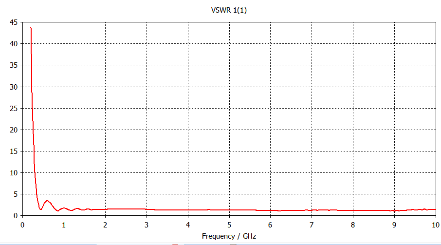 Figure 5: VSWR of AVA over frequency
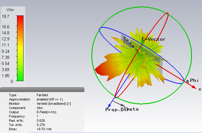
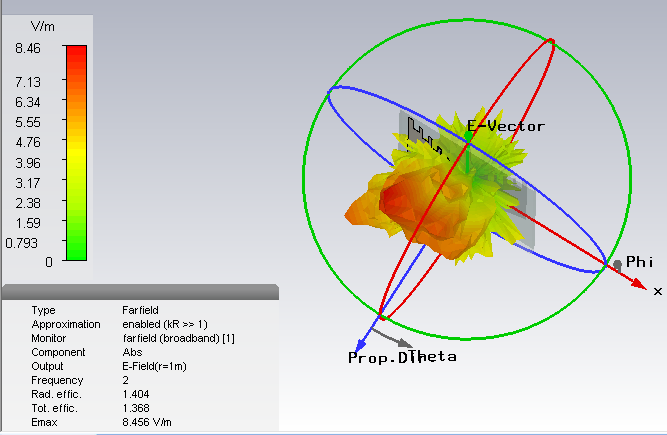
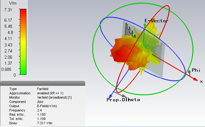
 At (a) 1GHz (b) 2GHz (c) 2.4GHz (d) 2.6GHz (e) 5GHz
Figure 6: Electric Field Radiation
 At (a) 1GHz (b) 2GHz (c) 2.4GHz(d) 2.6GHz (e) 5GHz
Figure 7: Directivity Pattern
4. Conclusion
AVA has a new shape model with a higher range of UWB from 1GHz to10 GHz. The antenna characteristics depict the performance such as the radiation pattern, the main lobe ,side lobe and electric fields. The linear improvements of gain illustrated the ability of antenna in indoor coverage solutions, where the cellular networks operators and providers for service strongly focus on this factor. Commercially, it can be utilized, designed and distributed on the walls and ceiling to produce a solution of indoor coverage issue in the present time. Moreover, the gain lineally increased between 5-10GHz is not limited to cellular networks technology, but also exploited in different applications such as UWB communications and X- band radar systems. However, the major drawback of this work is that AVA was not fabricated. Secondly, it needs further investigation for the gain reduction from 2GHz to 5GHz about 1.5dB. The reason, perhaps, due to data collection errors in simulation, since the gain should be increased linearly over the frequency when it increases. Otherwise, it may refer to the total losses contributed on the antenna structure at a specific band, although the comparisons between simulation and fabrication results lead to the facts on behind these minor issues. Overall, the abnormality of gain should not impact negatively on the essential innovation of antenna shape.
5. Acknowledgement
I am so grateful to University of Umm Al- Qural for tremendous assistance to keep me continued in both contribution and development in scientific research.
- Vinci and R. Weigel, “Multiband Planar Vival Antenna for Mobile Communication and Industrial Applications,”2010 International Conference on Electromagnetics in Advanced Applications, Sydney, NSW, 2010, pp. 93-96.
- Yang, H. Guo, X. Liu, H. Du and G. Ji, “An antipodal Vivaldi antenna for ultra-wideband system,” 2010 IEEE International Conference on Ultra-Wideband, Nanjing, 2010, pp. 1-4.
- Bai, S. Shi and D. W. Prather, “Modified Compact Antipodal Vivaldi Antenna for 4–50-GHz UWB Application,” inIEEE Transactions on Microwave Theory and Techniques, vol. 59, no. 4, pp. 1051-1057, April 2011.
- Fisher, James. “Design and Performance Analysis of a 1-40GHz Ultra-Wideband Antipodal Vivaldi Antenna.”Proceeding of the German Radar Symposium GRS 2000. 2000.
- Teni, N. Zhang, J. Qiu, and P. Zhang, “Research on a novel miniaturized antipodal Vivaldi antenna with improved radiation,” IEEE Antennas and wireless propagation letters, vol. 12, pp. 417-420, 2013.
- Aravinda Reddy, S. Natarajamani and S. K. Behera, “Antipodal Vivaldi antenna UWB antenna with 5.5GHz band- notch characteristics,” 2012 International Conference on Computing, Electronics and Electrical Technologies (ICCEET), Kumaracoil, 2012, pp. 821-824.
- Alsulaiman, Khaled A., et al. “Design of Ultra Wideband Balanced Antipodal Vivaldi Antenna for Hyperthermia Treatment.”PIERS Proceedings. 2013.