Finite Element Modeling for Wind Response of Aluminum Wall Cladding in Tall Building
Finite Element Modeling for Wind Response of Aluminum Wall Cladding in Tall Building
Volume 2, Issue 4, Page No 165-172, 2017
Author’s Name: Okafor Chinedum Vincenta), Mbanusi Echefuna Cyril, Kevin Chuks Okolie, Dominic Anosike Obodoh
View Affiliations
Department of Building, Nnamdi Azikiwe University, Awka, Nigeria
a)Author to whom correspondence should be addressed. E-mail: chinedumokafor117@yahoo.com
Adv. Sci. Technol. Eng. Syst. J. 2(4), 165-172 (2017); ![]() DOI: 10.25046/aj020422
DOI: 10.25046/aj020422
Keywords: Tall building, BS6399-2:1997, Finite element analysis, Aluminum wall cladding panel

Export Citations
This paper analyzed wind loading responses of Aluminum Wall cladding panels in Tall Building using Ikeja Lagos State Nigeria. The wind loads were calculated according to Standard and Specification From BS6399-2:1997 Using the wind speed data of Lagos state Nigeria and finite element analysis, we predicted the responses of these Aluminum wall Cladding panels to the design wind loads being calculated. The result of the calculation from BS6399-2:1997 showed that the aluminum cladding panels located on the facade upwind was subject to positive pressure, which increases with height. Also, the cladding panels located on the leeward, as well as sidewalls, were subjected to negative pressure, which tended to be high at the top and bottom corners due to flow separation. From the result of the modeling and analysis, the researcher found out that stresses on the aluminum wall cladding panels were generally below the material yield point, showing that the high wind speed were not the reason for the collapse of aluminum cladding panels in the locality being considered. Instead, the reality lies on one or more issue on the materials construction and placement as discussed.
Received: 26 July 2017, Accepted: 29 August 2017, Published Online: 05 September 2017
1. Introduction
The aerodynamics of tall buildings induced by the wind flow surrounding the building is characterized as that of a bluff body [1].The key factor affecting the aerodynamic loads on a bluff body include the approaching boundary layer wind, the characteristics of the bluff body and the condition of direct surrounding of the body such as presence of other bluff bodies [2].
Furthermore, buildings are obstructing the motion of air called wind, and as a result, the wind is exerting force on buildings [3].
Wind is composed of multitudes of eddies of varying sizes and rotational characteristics carried along in a general stream of air moving relative to the earth surface [4]. These eddies may give wind its gusty characteristic [4]. High wind speed of short duration are called gust. Large eddies whose dimensions are comparable with the structure tend to envelope the building (Figure 1) as they give well corrected pressure while small eddies result in pressure on various part of a structure that becomes practically unrelated with distance of separation[4]. Cladding on the other hand is the application of one material over another to provide skin or layer intended to control the infiltration of weather element or for aesthetic purpose. It is buildings envelop [5].
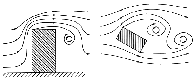 Figure 1: Generation of eddies
Today in Nigeria, many office building use aluminum cladding panel (figure 6) because it is versatile, lightweight and durable unlike other cladding materials. Aluminum cladding panels has certain recycling properties that help in creating a wide range of customized panel with metal finishes.
As is well known, the claddings and various building components are relatively small elements and their size is typically very small in relation to the entire structure [3]. So localized wind pressure variation according to BS6399-2:1997,[6] is required for their design and the analysis of the responses of the cladding panels to the design wind load is done using finite element analysis which is the subject matter of discussion in this paper.
Aim in this study is to analyze the wind loading responses of aluminum wall cladding panels of tall buildings using finite element analysis.
The study sought to achieve the aim through the following objectives to:
- Determine the magnitude of the design wind pressure on the wall cladding panels of the tall building,
- Calculate the wind speed at subsequent height of the tall building,
- Determine the static responses of the aluminum wall cladding panels to the design wind pressure, and
- Ascertain the regions on the wall cladding panel that require proper attention during the design and installation of the panel.
- Flow phenomenon
- Positive pressure
| V |
| Height |
| V, P |
| wind |
| High +ve pressure |
| Intermediate +ve pressure |
| Low +ve pressure |
| High +ve pressure |
| Plan |
| Low +ve pressure |
| Windward wall |
| Windward wall |
As shown in Figure 2, the maximum positive pressures generally occur at the windward wall and all facades will become windward for certain wind directions. The cladding panels located on that wall will become windward for same reason. The positive pressure increases as height increases which mean that the lower part of the building will be subjected to lower positive pressure and the top part of the building subjected to higher positive pressure except the top edges were the wind tends to negotiate with the edge, which results in lower positive pressure.
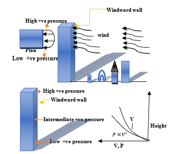 Figure 2: Pictorial representation of positive pressures acting on building facade.
- Negative pressure
Cladding panels located at the leeward wall, as well as sidewall of the tall building, are subjected to negative pressures (suction) which are very high at the corners of the tall building due to flow separation [3]. Suction can also be very high at the top-bottom corner region due to intense flow separation. The increase of these suction or negative pressure is mainly due to the shape of the building and not associated with increase in height and speed of the wind.
| PLAN |
| PLAN |
| Side wall |
| Leeward wall |
| Wind |
| Windward wall |
| High suction |
| Low suction |
| High suction zone |
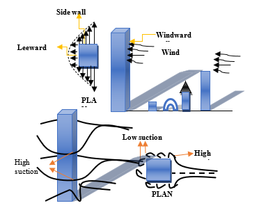 Figure 3: Pictorial representation of negative pressures acting on building facade.
- Flow separation
Pressure gradient is one of the factors that affect flow immensely. A negative pressure gradient is termed a favorable pressure gradient because it enhances the flow of the wind while a positive pressure gradient is termed an unfavorable pressure gradient because it retards the flow.
From Figure 4 below, we have adverse pressure gradient downstream of S2, this effect is felt more strongly in the region close to the windward wall of the tall building where the momentum is lower than in the region near the free stream. A continuous retardation of the flow brings the wall shear stress at the point S2 on the windward wall to zero. From these point onwards, the shear stress becomes negative (S3) and the flow reverses and a region of recirculation flow develops (figure 3).
We can see in figure 3 that the flow no longer follows the contour of the tall building. We say that the flow has separated. The point (S2) where the shear stress is zero is called the point of separation. Depending on the flow conditions, the recirculation flow terminates and the flow may become reattached to the body. A separation bubble was also formed (figure 3).
There are various factors that can influence this reattachment one of which maybe that the pressure gradient has become more favorable due to body geometry or that the flow which was initially laminar may have undergone transition within the bubbles and may become turbulent [7]. A turbulent flow has more energy and momentum than laminar flow and this can kill separation and flow may re-attach.
- Methodology
- Research Designs
The proposed study work is mainly focused to analyze the wind loading responses of aluminum wall cladding panels of a typical tall building.
The procedure employed in order to achieve this aim is outlined below:
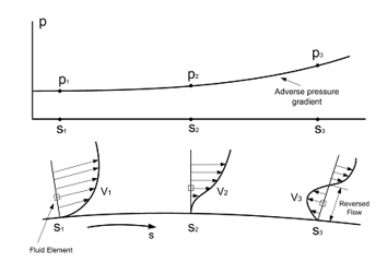 Figure 4: Pressure gradient and flow separation.
- Getting a proper record of the wind speed distribution of the locality in consideration (Ikeja, Lagos state Nigeria).
- Using the wind profile power law equation to determine the wind speed at subsequent heights for the 15th storey high rise building.
- Calculating the values of the wind pressure on the Aluminum wall claddings using wind loading codes (BS6399-2-1997).
- Analyzing the responses of the aluminum wall cladding to the wind pressure using LISA finite element analysis software.
- Area of the Study
For the research work, wind speed data of Ikeja, Lagos state, Nigeria was used with reference to the wind speed map of Nigeria determined from 40years of measurement at 10m height.
 Figure 5: Nigerian wind map in m/s determined from 40 years measurements at 10m height, obtained from Nigerian metrological department, oshodi,lagos state, Nigeria(NIMET).
- Case study
The building selected for this part of the case study was a 62m x 30.5m x 47.8m, 15- story typical office building (Figure 6). A 1.22m parapet was provided above the roof making total height of the building equal to 48.8m. The structural system contained reinforced concrete rigid frames in both directions as shown in Figure 6. The floor slabs were assumed to provide diaphragm action. The wall cladding panels are 120mm (width) × 2440mm( length)×4mm (thickness)
 Figure 6: Structural system of the 48.8m tall building
- Analytical procedure
From the wind speed map above it can be deduced that Lagos State (Ikeja) has a wind speed of 3.40m/s measured from a 10 meter height. Using the power law, wind speed at subsequent height can be calculated with results, as follows:
The wind profile power law relationship is:
Where u is the wind speed (in meters per second) at height z (in meters), and is the known wind speed at a reference height . The exponent (a) is an empirically derived coefficient that varies dependent upon the stability of the atmosphere. For neutral stability conditions, is approximately 1/7, or 0.143.
In order to estimate the wind speed at a certain height (z), the relationship would be rearranged to:
The fundamental wind speed of the tall building 15th floor = 4.256m/s
Now, the Design wind speed can be calculated as
To determine the standard effective wind speed
Calculate the dynamic pressure
To calculate the external wind pressure on the windward wall of the tall building.
Table 1: Fundamental wind speed as per wind speed power law equation
| Storey | Wind Speed(m/s) |
| 15th floor | 4.256 |
| 14th floor | 4.203 |
| 13th floor | 4.159 |
| 12th floor | 4.112 |
| 11th floor | 4.061 |
| 10th floor | 4.000 |
| 09th floor | 3.946 |
| 08th floor | 3.880 |
| 07th floor | 3.807 |
| 06th floor | 3.724 |
| 05th floor | 3.628 |
| 04th floor | 3.514 |
| 03th floor | 3.372 |
| 02th floor | 3.182 |
| 01st floor | 2.883 |
According to table 5 of [6], Cpe for leeward wall and sidewall have negative values which accounts for the negative values of the wind pressures shown in table 3.
Where Vs is the site wind speed, Vb is the basic wind speed, Ve is standard effective wind speed, Sa is an altitude factor, is the site altitude in meters, Sd is a direction factor, Ss is a seasonal factor, Sp is a probability factor, Sb is the roughness factor, qs is the dynamic pressure, Pe stands for the wind pressure, Ca is the size effect factor for external pressure, Cpe is the external pressure coefficient for the building surface.
- Finite element modeling
The static analysis of the response of the aluminum wall cladding panels to wind was carried out using LISA FINITE ELEMENT SOFTWARE.
It was done firstly, by modeling the typical aluminum cladding panel with standard size of 120mm (width) × (2440mm) lenght×4mm (thickness) fixed at each ends.
Table 2: Mechanical material properties of Aluminum wall cladding panel
| Young modulus | 72Gpa |
| Poisson ratio | 0.33 |
| Density | 5.5kg/m3 |
| Ultimate tensile strength | 110 to 180mpa |
| Yield strength | 120mpa |
| Shear modulus | 26Gpa |
| Shear strength | 110mpa |
The Figure above is a finite element model of a typical Alloy EN AW-3103(Al Mn1) aluminum wall cladding panel of standard size of 1200mm (width) .
 Figure 7A: Analytical model of the aluminum wall cladding panel showing nodes.
 Figure 7B: Analytical model of the aluminum wall cladding showing element surface
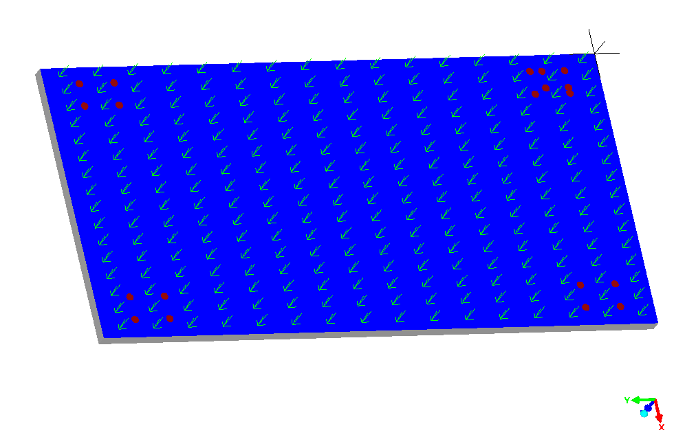 Figure 8: Analytical model of the aluminum wall cladding subjected to varying design wind pressure.
These aluminum cladding panels are fixed at the ends and subjected to wind loads calculated as per BS6399-2:1997 at different floors.
- Result
Table 3: Design of wind pressure on the aluminum cladding panels of the tall building
| Floor | Hr(m) |
Pe wind-ward (Pa) |
Pe lee- Ward (Pa) |
Pe sidewall Zone A(Pa) |
Pe sidewall Zone B(Pa) |
| 15th floor | 48.77 | 47.702 | -28.060 | -72.956 | -44.896 |
| 14th floor | 44.1 | 45.297 | -26.645 | -69.277 | -42.632 |
| 13th floor | 40.95 | 43.622 | -25.660 | -66.716 | -41.056 |
| 12th floor | 37.80 | 42.267 | -24.863 | -64.649 | -39.784 |
| 11th floor | 34.65 | 40.707 | -23.945 | -62.257 | -38.312 |
| 10th floor | 31.5 | 38.989 | -22.935 | -59.631 | -36.696 |
| 9th floor | 28.35 | 37.068 | -21.960 | -57.096 | -35.136 |
| 8th floor | 25.2 | 34.644 | -20.795 | -54.067 | -33.272 |
| 7th floor | 22.05 | 32.155 | -19.655 | -51.103 | -31.448 |
| 6th floor | 18.9 | 29.331 | -18.355 | -47.723 | -29.368 |
| 5th floor | 15.75 | 26.009 | -16.845 | -43.797 | -26.952 |
| 4th floor | 12.6 | 22.121 | -15.110 | -39.286 | -24.176 |
| 3rd floor | 9.45 | 17.423 | -13.100 | -34.055 | -20.957 |
| 2nd floor | 6.30 | 12.438 | -10.365 | -26.954 | -16.587 |
| 1st floor | 3.150 | 8.2740 | -6.895 | -17.927 | -11.032 |
- Case 1 for cladding panels located at the windward wall of the 15th floor subjected to positive wind pressure of 47.702
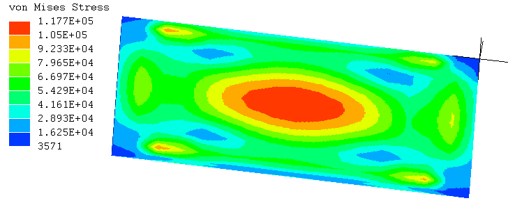 Figure 9: Von mises stress on the cladding panel
Von mises stresses of the cladding for characteristic wind pressure of 47.702N/M2 was shown in figure 20. The largest stress occurs at the centre of the panel, and its value was 0.117Mpa. According to [8], the minimum to maximum yield tensile stress of 3013 Aluminum sheet is 120mpa. From the result shown in figure 14, the maximum von mises stress was 0.117mpa which is smaller than 120mpa.
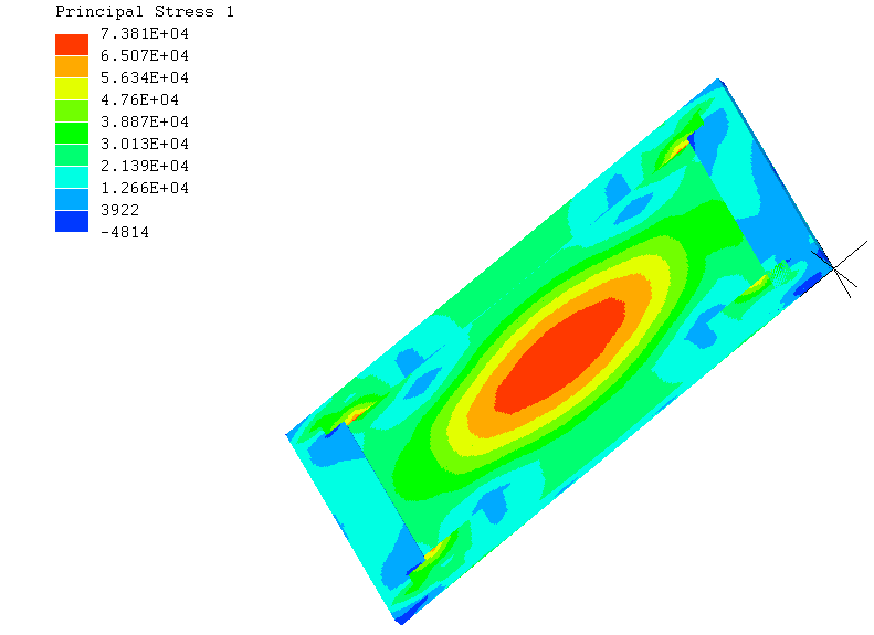 Figure 10: Principal stress 1 of the cladding panel.
According to maximum principle stress theory, failure will occur when the maximum principal stress in a system reaches the values of the maximum strength at elastic limit in simple tension test. From the image above, it can be deduced that the maximum normal stress that occurred at the major principal plane was located at the centre of the panel with value of 0.6348MPa. In [8], the ultimate tensile strength of 3103 aluminum is between 110 to 180Mpa. 0.6348MPa is less than 110MPa.
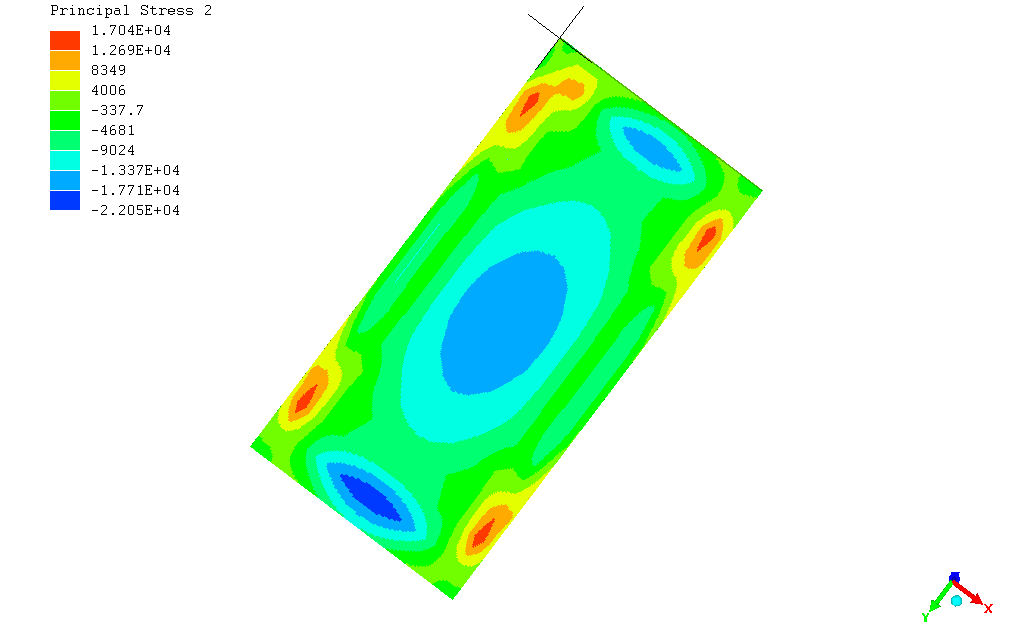 Figure 11: Principal stress 2 of the cladding panel.
The maximum normal stress that occurs at the principal plane 2 is located at the region where the fasteners are attached with maximum principal stress of 0.01704MPa. This principal stress was lower than the ultimate tensile stress of the cladding panel.
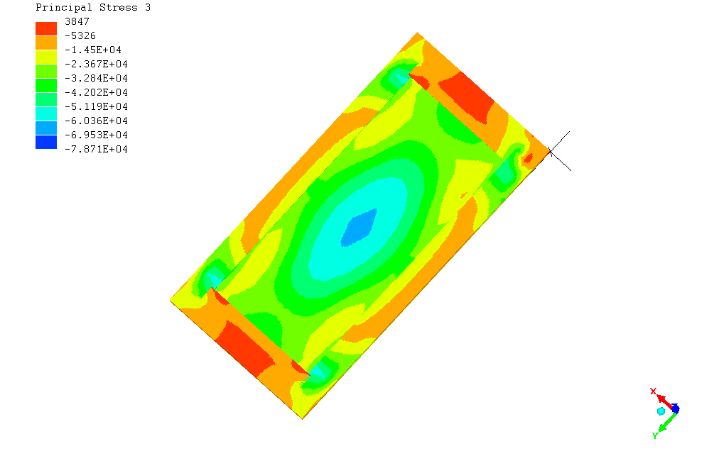 Figure 12: Principal stress 3 of the cladding panel.
The major principal stress 3 on the cladding panel is shown on the diagram above with maximum value of 0.003847Mpa.
- Case 2 for cladding panels located at the 15th floor of the leeward wall while being subjected to a design wind pressure of -28.060N/M2
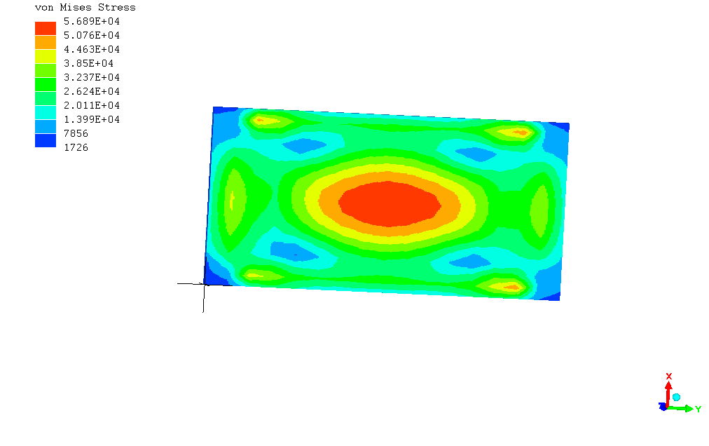 Figure 13: Von mises stress of the panel.
The largest stress was recorded at the centroid of the panel with a value of 0.05689MPa knowing that the panel was supported at the ends. This stress is less than the yield stress of 120mpa.
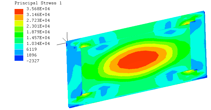 Figure 14: Principal stress 1 of the cladding panel.
From the principal stress contour diagram in Figure 14, the maximum normal stress acting on the major principal plane of the panel occurred at the center of the panel with a value of 0.03568MPa. This value was smaller than 110mpa.
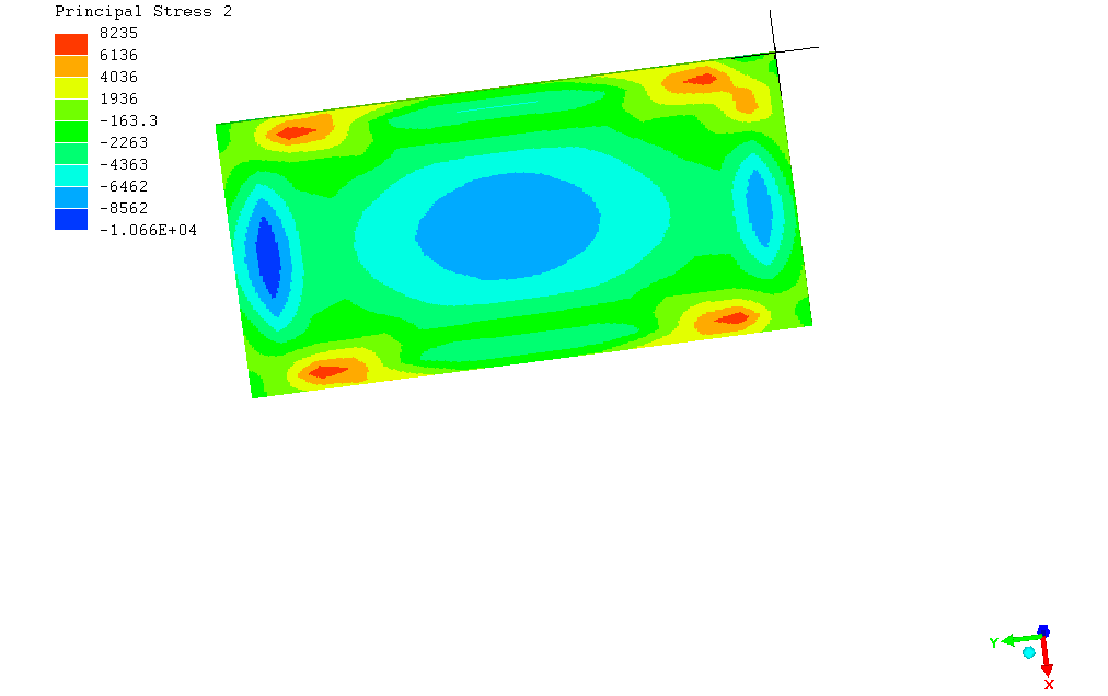 Figure 15: Principal stress 2 of the cladding panel.
According to [8], the stress limit for 3013Aluminium sheet is 110mpa. From the result shown in figure 15, Maximum principal stress=0.008235MPa, which was smaller than 110mpa.
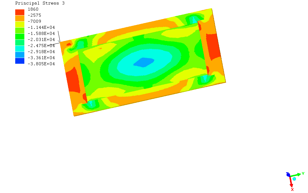 Figure 16: Principal stress 3 of the cladding panel.
From figure 16, the major principal stress =0.001860Mpa which was smaller than 110mpa.
- Case 3 for cladding panels located at the zone B side wall of the 15th floor subjected to suction wind pressure of -44.896Pa.
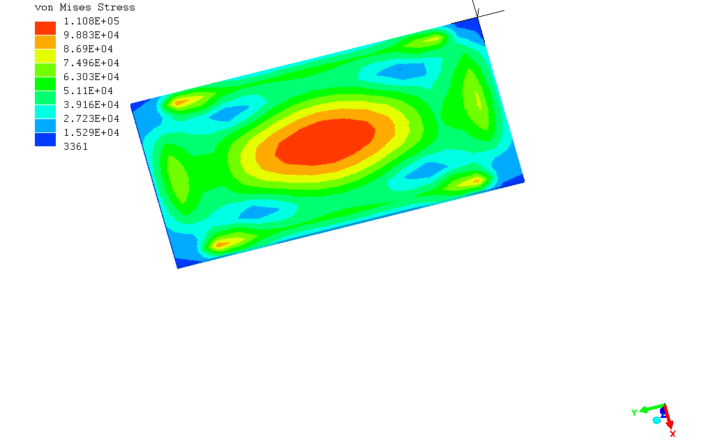 Figure 17: Von mises stress of the cladding panel
From the contour diagram in figure 17, the maximum von mises stress was located at the centre of the panel. Also because the panel was supported at the 4 sides, the wall cladding was deformed inwards from the centroids when normal pressure applied on the panel. The value of this maximum von mises stress was 0.1108MPa which was smaller than 120Mpa.
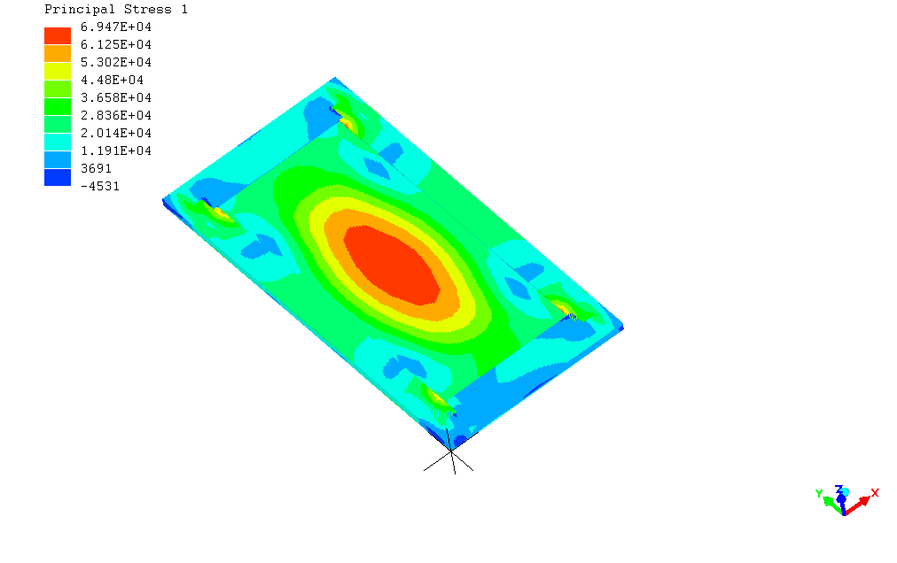 Figure 18: Principal stress 1of the cladding panel
Major Principal Stress=0.06947MPa which was lower than 110MPa.
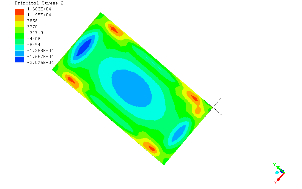 Figure 19: Principal stress 2 of the cladding panel
Major Principal stress 2=0.01603 MPa which was also lower than 110MPa.
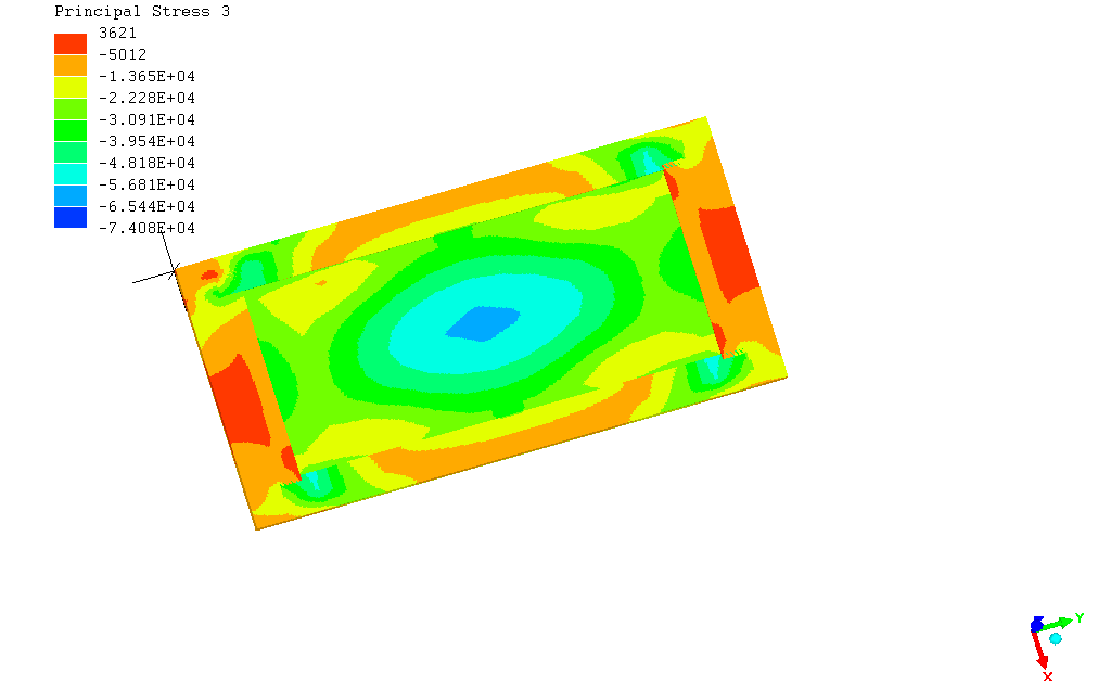 Figure 20: Principal stress 3 of the cladding panel.
Major Principal Stress=0.003621MPa which was lower than 110MPa.
- Case 4 for cladding panels located at the zone B side wall of the 15th floor subjected to suction wind pressure of -72.956Pa.
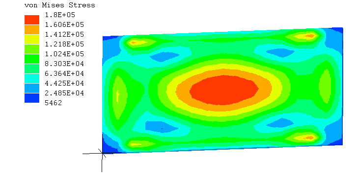 Figure 21: Von mises stresses of the cladding panel.
From the contour diagram in Figure 21, the maximum von mises stress was located at the centre of the panel. Also because the panel was supported at the 4 sides, the wall cladding was deformed inwards from the centroids when normal pressure applied on the panel. The value of this maximum von mises stress was 0.1800MPa which is smaller than 120MPa.
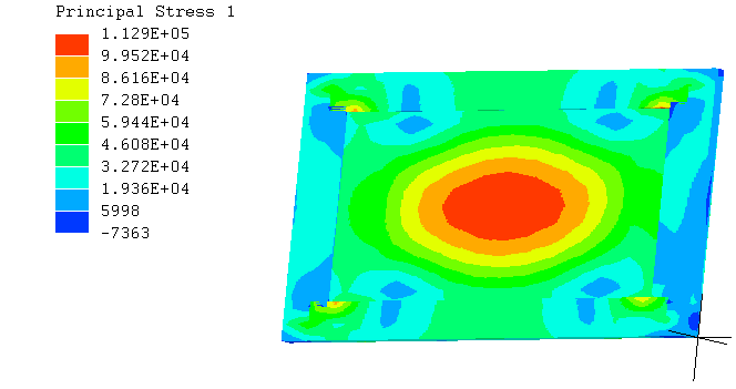 Figure 22: Principal stress 1 of the cladding panel
Major Principal Stress= 0.1129 MPa which was lower than 110MPa.
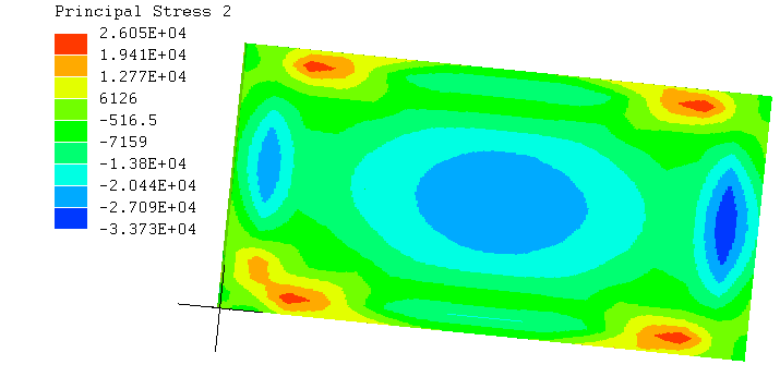 Figure 23: Principal stress 2 of the cladding panel
Major Principal Stress=0.2605 MPa which was lower than 110mpa.
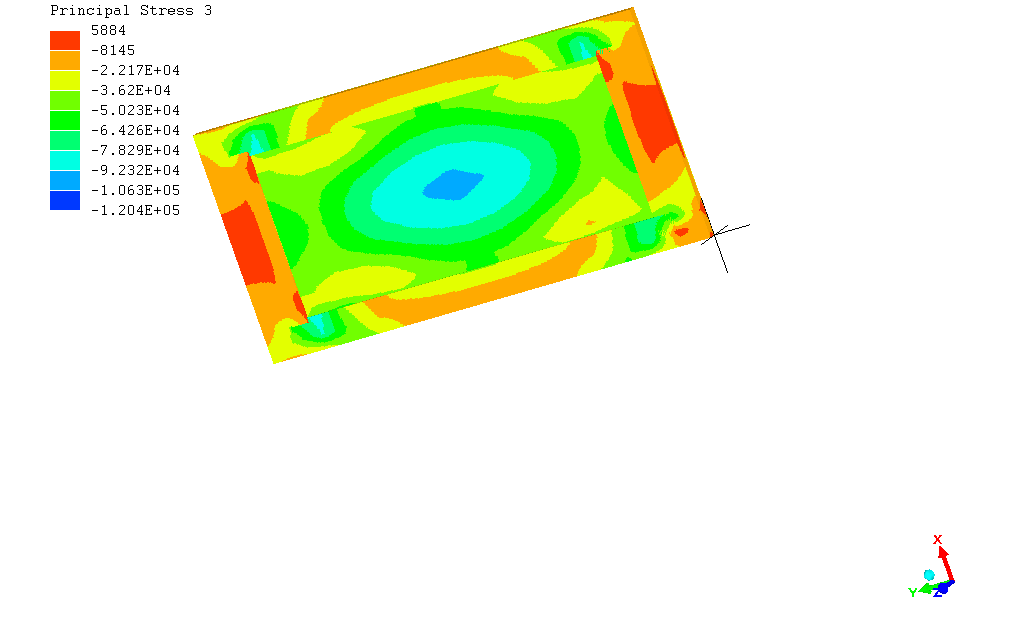 Figure 24: Principal stress 3 of the cladding panel
Major Principal Stress=0.005884 MPa which was lower than 110MPa.
- Discussion and Conclusion
Based on the results, the writer believes that the high wind speeds were not responsible for the failure of Aluminum wall cladding panels in ikeja Lagos state in Nigeria; instead, the failures lies on one or more of the reasons explained below.
- Poor workmanship and inadherence to installation details: The writer believes that poor workmanship and inadherence to application and installation details in the part of the cladding installer can seriously result in the incessant failure of cladding panels in the region being considered. These may include:
- Incorrect fixing of the panel to the supporting framework
- Insufficient allowance for panel movement
- End grain and onsite cuts not being sealed
- Dark colored finish: The use of light colored paint is highly recommended for cladding. Research has clearly demonstrated that light colored paint provides much better service life for both the panel and paint used externally. Dark colored surface (especially on the north or west facing walls) heat up significantly more than light colored surface and this in turn will cause the panel to shrink and movement may lead to splitting.
As a rule of thumb, the light reflective value (LRV) of the paint should be greater than 30% or a total solar reflective value (TSR) greater than 29%. This will ensure your paint color is not too dark [9]. Heat reflective paints should be used where possible.
- Use of lower quality aluminum cladding panels: The use of lower quality aluminum cladding panels can result to failure of cladding panels when subjected to minimal wind loads. It is recommended that the installer check the basic feature of the cladding panel before purchasing it. A durable cladding panel should have the following features.
Alloy Used- AA3103
Feature of the cladding panel before purchasing it. A durable cladding panel should have the following features.
Alloy Used- AA3103
Panel Thickness- 4mm (reference thickness)
Weight- 5.5kg/m2
Tensile Strenght-40N/MM2
Coating- PVDF Based fluorocarbon coating
Warranty- 10 years
- Recommendation
Claddings are a critical and important architectural feature of a building and represent a significant portion of the overall cost of a building construction [10]. Given the ever growing complexity and variety of modern building envelopes, the evaluation of their performance, in terms of structural integrity and durability as well as comfort requirements, in the pre-construction and construction phase is essential in order to avoid undesirable and costly problems during the service life of the building.
On this premise, the researcher recommends that the following tests should be carried out before cladding installation.
- pre-construction mock ups
- Curtain wall air infiltration test
- Structural performance test
- Areas for further study
There are still some areas in which detail study is required. One of which is:
- Analyses of the responses of Aluminum wall cladding panels to vortex shedding in high rise building.
- Analysis of the responses of the entire Aluminum wall cladding system to wind loading in High-rise buildings
- Roshko, “Perspectives on bluff body aerodynamics”. Journal of wind Engineering and Industrial Aerodynamics, 49, 79-100(1993)
- K. Bernard, “prediction of wind loads on Tall building” PhD thesis. University of western ontini, (1993).
- K. Suresh, wind tunnel testing for design of building façade,WFM team,2016
- P. Mendis, T. Ngo, N. Haritos, A. Hri, B. Samali, J. Chueng, “wind loading on tall building” journal of structural Engineering 2(2)2007,41-54(2007)
- Z. Ftihah, “Case Study Of Cladding” http://www.prezi.com(2014)
- BS 6399-2:1997. Loading for Buildings-part 2: “code of practice for wind loads”.BSI
- Aerospace,Mechanical&Mechatronic Engg “Separation Of Flow”. University of Sydney, (2005)
- BS EN 485-2:2007 “Aluminum and aluminum alloys”. Sheet, strip and plate. Mechanical properties.BSI
- Design pine, “Cladding Installation, design pine group,2013
- Team WFM, “Façade Testing Procedure,WFM team,2015