Design and Construction of a remote control switching device for household appliances application
Design and Construction of a remote control switching device for household appliances application
Volume 2, Issue 4, Page No 154-164, 2017
Author’s Name: Mbunwe Muncho Josephinea)
View Affiliations
University of Nigeria Nsukka, Electrical Engineering, University of Nigeria Nsukka, 410001, Nigeria
a)Author to whom correspondence should be addressed. E-mail: mamajoesix@gmail.com
Adv. Sci. Technol. Eng. Syst. J. 2(4), 154-164 (2017); ![]() DOI: 10.25046/aj020421
DOI: 10.25046/aj020421
Keywords: Remote Control, Radio Frequency , Transmitter System, Receiver System, Security System

Export Citations
Remote control switching device for household application is a home device used to control the switching of household appliances from a distance. It serves to make the switching of household appliances easy for the elderly, physically challenged, the young and anyone who, in any circumstance, needs comfort and security. This paper develops a remote control system using the Radio Frequency technology utilizing multiplexers, demultiplexers, encoders, decoders, and Radio Frequency module with the analysis of various technologies which can be used for the development of a remote control system. A security system is incorporated in this remote control to provide a secured usage of the system from a distance of about ten meters away. To achieve the aim of this work: a transmitter system is design and constructed which processes and sends out signal when a button is pressed; the construction of a receiver system which receives and processes the signal from the transmitter system, then turn on or turn off the appliances; and incorporate a security system which allows transmission of signal only when certain condition is met. Avoiding the use of microcontroller, this paper developed an affordable, reliable and effective remote control system for household applications.
Received: 25 March 2017, Accepted: 22 August 2017, Published Online: 04 September 2017
- Introduction
Remote controls devices are devices that sends digitally-coded pulses to control functions like power, volume, tuning, temperature set point, fan speed, just to name a few, to control different equipments. These devices are usually small wireless handheld objects with an array for various adjustable setting buttons for television channel, track number, and volume. For many devices, the remote control contains all the function controls while the controlled device itself has only a handful of essential primary controls. The earlier remote controls used ultrasonic tones [1]. Remote control has continually evolved and advanced over recent years to include Infrared (IR), Radio frequency, Bluetooth connectivity, motion sensor-enabled capabilities, voice control. IR remote control has been proved to be the most popular equipment for office application, for example, control of air conditioner, turn on or switch off light as well as the normal use of satellite receivers and Televisions [2]. In this paper, while implementing the use of various technologies incorporating security, a remote control system which uses the radio frequency technology is developed.
1.1. Background of remote control switching device
Most homes make use of many electrical and electronics appliances such as the television set, standing fan, ceiling fan, air conditioner, lighting bulbs, video players, radio, etc. All these appliances require switching to turn on and turn off these appliances traditionally. This manual switching of any home appliance is an inconvenient method for physically disabled or elderly or even for the young and busy individuals when frequent switching operation is required. Thus, an easier method of switching is developed to replace this manual switching method, using an advanced switching method for electronic home appliances.
The early wired remotes made possible for users to control appliances at a distance, but the wired remote also limited the user’s mobility by either tethering or tripping the users. If the user ran the remote control’s cord under the rugs and furniture, effectively anchoring the device to one location in the room, the remote thereby limits the freedom of movement for which it was designed to provide. But if the cord is left out in the open, the users might stumble over it. The wireless remote control solved all these challenges of the wired remote control and effectively takes control of the household. The use of remote to restore order to the household [3], changes life style; brings multi-function and multi-platform lives easy.
Various technologies have evolved in the past: controlled by radio waves; used to execute commands transmitted by electromagnetic waves; and also the use of battery-operated low-frequency radio transmitter remote control for consumer electronics [4]. The idea for an electronic remote control, which worked wirelessly by shining a beam of light onto a photoelectric cell, came up in the United State in 1955 [3, 4]. Advancement in remote control kept going till recent days where many technologies such as infrared, radio frequency, Bluetooth, Global System for Mobile (GSM) communications control are used for remote control.
The major technology used in home remote controls is infrared (IR) light [2]. The signal between a remote control handset and the device that it controls consists of pulses of infrared light, which is invisible to the human eye, but can be seen through a digital camera, video camera or a phone camera. The transmitter in the remote control handset sends out a stream of pulses of infrared light when the user presses a button on the handset. A transmitter is often a light emitting diode (LED) which is built into the pointing end of the remote control handset. The infrared light pulses form a pattern unique to that button. The receiver in the device recognizes the pattern and causes the device to respond accordingly. Radio Frequency (RF) remote control is used to control distant objects using a variety of radio signals transmitted by the remote control device. As a complementary method to infrared remote controls, the radio remote control was used with electric garage door or gate openers, automatic barrier systems, burglar alarms (for security and also for restriction of the use of household appliances) and industrial automation systems [3]. The importance and benefit of remote control for household applications using radio frequency technology varies:
- It is not affected by line of sight.
- It penetrates most solids materials and passes through walls.
- It transmits signals to longer range, more than that of infrared technology.
- It is not sensitive to light, to weather or any environmental conditions.
This paper is confined to the use of Radio Frequency (RF) technology in switching to control household appliances which involves:
- The design and construction of a transmitter circuit that switches to send signal to the receiver circuit using the RF technology.
- The design and construction of a receiver circuit that receives signal from the transmitter circuit via RF technology then acts to switch on or off a household appliance.
2. Remote control Technologies
Years ago some remote control made use of wires, but modern remote control now works based on wireless communication. This allows information to be exchanged between two devices without the use of wire or cable [5]. There are various technologies that can be used for developing wireless remote control for household application. Each technology has its own merits and limitations. Various works have been done by different people on different remote control:
2.1. Infrared control
The dominant remote-control technology in home applications is the infrared (IR), also known as “heat”. The basic premise at work in an IR remote control is the use of light to carry signals between a remote control and the device it is directing. Infrared light is in the invisible portion of the electromagnetic spectrum [2-4]. Infrared remote control for home appliances works based on technology similar to the Television remote operation. Infrared radiation is the region of the electromagnetic spectrum between microwaves and visible light. In infrared communication an LED transmits the infrared signal as bursts of non-visible light. At the receiving end a photodiode or photoreceptor detects and captures the light pulses, which are then processed to retrieve the information contained. An Infrared remote control transmitter sends out pulses of infrared light that represent specific binary codes [2]. These binary codes correspond to commands, such as Power ON or Power OFF. The receiver receives the signal and the microprocessor carries out the corresponding command [1]. The infrared receiver sits on the front of the device where can easily get the incoming signal from the remote control. In an infrared remote, when a push button is pressed, the integrated circuit detects it and sends the binary command to the LED at the front of the remote [2] as shown in Figure 1.
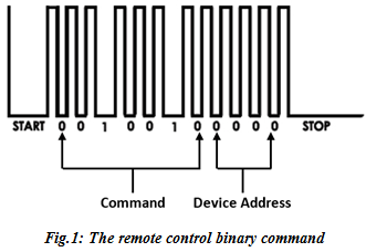 Figure 1. The remote control binary command
The LED sends out a series of light pulses that corresponds to the binary command to the receiver. In Figure 1, the ‘start’ indicates when the button is pressed while the ‘stop’ indicates when the button is released. When the infrared receiver on the appliance picks up the signal from the remote and verifies from the address code that it is supposed to carry out this command, it converts the light pulses back into the electrical signal. This signal now passes to the microprocessor, which carries out the intended command. Figure 2 shows the two circuits for an infrared control [2]: the transmitter and the receiver circuits.
 Figure 2. Block diagram of infrared control
The transmitter circuit consists of the power supply which is usually a battery supplying the required voltage for the encoder and the IR transmitter. There is the encoder which encodes the information received from the switches and then generates a modulated signal which is sent to the transmitter. This encoder can be an Integrated Circuit (IC) 555 timer which acts as an actable multi-vibrator whose output makes the IR transmitter to be in high state and produce the infrared beam through the concave lens of the IR LED [6]. This infrared beam produced from the infrared LED travels in a straight path is then transmitted to the receiver circuit. The receiver circuit consists of the power supply, the infrared receiver, the decoder, the relay driver and the relay, and this connects the appliance controlled to the mains power supply. The power supply of the receiver circuit is usually connected from the mains through rectification as the circuitry uses DC voltage. The infrared receiver is a photo diode which is usually the IC’s (TSOP 1738 or TSOP 1740), whose output is high when idle and goes low when it receives a signal [6]. The received signal is transmitted to the decoder or demodulator which demodulates the frequency of the signal and activates the relay driver which triggers the relay to be activated or deactivated. The activation and deactivation of the relay brings about a switching operation which turns on or turn off the connected appliance.
The infrared remote control has the performance of the high signal to noise ratio, strong anti-interference, reliable transmission of information, and untouchable, low power and affordable [1]. This remote is also use for industrial control, the aerospace, the security and so on. The disadvantages of using infrared includes: being limited to line of sight; the transmitters and receivers must be almost directly aligned (that is, able to see each other) to communicate [2]. It is easily blocked by materials such as people, walls, and plants and has short range; as a result, it performance drops off with longer distances. It is light and weather sensitive; direct sunlight, rain, fog, dust, pollution can affect transmission. The data rate transmission is lower than typical wired transmission [1].
2.2. Radio Frequency (RF) control
Instead of sending out light signals, an RF remote transmits radio waves that correspond to the binary command when the button is been pressed. Radio frequency (RF) is any of the electromagnetic wave frequencies that lie in the range extending from 3 kHz to 300 GHz, which include those frequencies used for communications or radar signals [7]. When a RF current is supplied to an antenna, it gives rise to an electromagnetic field that propagates through space. Any RF field has a wavelength that is inversely proportional to the frequency. A radio receiver on the controlled device receives the signal from the radio transmitter and decodes it. RF remote control system is designed for controlling the power switch of household appliances [7]. It consists of two parts: the remote controller which consists of a transmitting unit and a power amplifier which generates modulated RF signals and sends it out when a function button is pressed. The other part is placed in the household appliances section that is made up of a receiving unit and a power management block. It receives and demodulates the signal and send to the power management block [6, 7]; and relay using battery supply to boost the energy coming from the received RF signal to open or close the power switch of the electrical equipment as shown in Figure 3.
Radio remote control is used to control distant objects using a variety of radio signals transmitted by the remote control device. This type of control makes use of the radio waves for signal transmission. RF remotes tend to cost a bit more, have longer range, and is not affected by line of sight as is the case for Infrared. However, it cannot be used for very long range and any transmitter operating in the range can carry out the control.
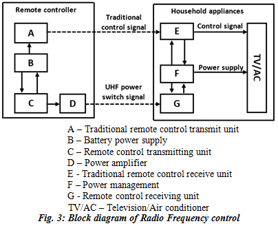 Figure 3. Block diagram of Radio Frequency Control
2.3. Global system for mobile communication module
The Global System for Mobile (GSM) communication module (SIM900) is a complete Quad-band GSM/GPRS device which can be embedded in circuits. The SIM900 delivers GSM/GPRS 850/900/1800/1900MHz performance for voice, SMS, Data, and Fax in a small form factor and with low power consumption [8]. It is equipped with analog audio interface, Analog to Digital (A/D) converter, Antenna pad, Serial interface which enables the interfacing of the SIM900 to micro controller.
2.3.1. Remote control using SIM900
The GSM control with the SIM900 makes use of the GSM mobile network which uses a sim card and is interfaced directly to the micro controller. This control method is used [8] to control the household appliances remotely. The medium of transmission in this control is the mobile network. With this, it will be convenient to control any device wirelessly, especially helpfully for outdoor remote control. SMS sent to the sim card in the network module is read by the micro controller. The micro controller is then programmed to carry out a switching task when it receives a preset SMS.
If the message is preset in the micro controller program, the micro controller then triggers a relay corresponding to the specified load to activate and make the circuit of that load and the mains. If a different message is sent to the GSM module as specified in the micro controller to turn off a particular load, the micro controller sends a low output to the relay to deactivate to break the circuit of the specified load and the mains. Merits of this control includes its ability to control home appliances over any range as long as there is GSM network at the receiver station and the transmitter station [7, 8]. The micro controller can also be programmed to give a feedback on successful turning on or turning of an appliance. It can control as many appliances as there are output pins of the micro controller.
Its high cost with the cost of buying the micro controller and programming of the micro controller adds to the demerits of this control method. This control method cannot be used in a remote area where there is no GSM network. Also, this control consumes user airtime when sending a control signal.
2.3.2. Dual-Tone Multi-Frequency application
Dual-tone multi-frequency (DTMF) signaling is an in-band telecommunication signaling system using the voice-frequency band over telephone lines between telephone equipment and other communications devices and switching centers. The DTMF system uses a set of eight audio frequencies transmitted in pairs to represent 16 signals, represented by the ten digits, the letters A to D, and the symbols # and * [9]. These ten digits, letter A to D and symbols # and * forms the telephone keypad. Modern telephone got rid of the letters [10]. The DTMF telephone keypad is laid out in a 4×4 matrix of push buttons in which each row represents the low frequency component and each column represents the high frequency component of the DTMF signal. Pressing a key sends a combination of the row and column frequencies [9]. For example, the key 1 produces a super imposition of tones of 697 and 1209 hertz (Hz). This is shown in Table I.
Table I. DTMF Keypad Frequencies
| 1209 Hz | 1336 Hz | 1477 Hz | 1633 Hz | |
| 697 Hz | 1 | 2 | 3 | A |
| 770 Hz | 4 | 5 | 6 | B |
| 852 Hz | 7 | 8 | 9 | C |
| 941 Hz | * | 0 | # | D |
2.3.3. Remote control using DTMF
This system adopts existing common telephone network to realize remote control. As long as main control terminal is in the range of GSM, it can make use of the working method of DTMF to realize the communication between transmission and reception. DTMF signals are widely used and concerned because of its low power consumption, strong anti-interference, less peripheral parts, large code capacity and easily interfaced with all kinds of sensors. DTMF receiver includes DTMF grouping filter and DTMF decoder. It is composed of a group of low audio signals and a group of low audio signals. In the GSM control using DTMF technology, a mobile phone serves as the transmitter, in the receiver section, another mobile phone serves to receive the transmitted signal which is the mobile/GSM modem as shown in the control block diagram of Figure 4.
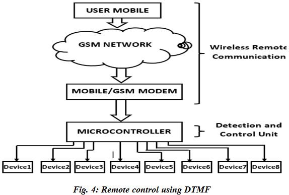 Figure 4. Remote control using DTMF
The mobile phone in the transmitter section is set to automatically answer calls, and it is interfaced to the DTMF decoder through the headset port. When the phone transmitter calls the phone receiver, it automatically answers, any key pressed on the phone transmitter sends a code according to the Table 1 above to the DTMF decoder, the DTMF decoder decodes this code and sends a 4-bit output to the micro controller, the micro controller is programmed to react to this inputs from the DTMF decoder [9]. For specific key pressed, the micro controller may be programmed to output a high to trigger the relay to activate and make the circuit of the home appliance and the mains, and for another key pressed, the micro controller is programmed to output a low to deactivate the relay and break the circuit of the home appliance and the mains.
DTMF control takes full advantages of the public switched telephone network, which makes it realize the remote control and receive the full-duplex communication [11]. The transmission distance of the control signal is not restricted as long as there is GSM network where the phone transmitter is, and there is a GSM network at the location of the receiver. The limitation of this control is that the number of home appliance it can control is limited to the keypad of a phone which is twelve in number; six keys to turn on and six keys to turn off appliances.
2.4. Descriptions of components
The various components used to achieve a Radio Frequency remote control include:
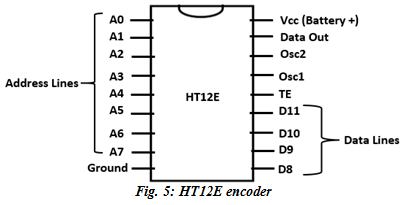 Figure 5. HT12E encoder
These IC, HT12E is of the family of encoders which is capable of encoding information which consists of N address bits and 12 – N data bits [12]. The ‘12’ in the name means 8 address lines and 4 data lines while E letter represents ‘Encoder’. The four data lines of this encoder are the four input lines. These lines are used to give input which is to be encoded. In encoding, data is being wrapped up. For instance, if a binary signal ‘1001’ is needed at the output end, it is required to make data pins as ‘1001’. To make the data pin like this, ‘high’ or 5 volts (which digitally means ‘1’) is fed to pins ‘D0’ and ‘D3’ while ‘low’ or 0 volts (ground) is fed to pins ‘D1’ and ‘D2’. This together gives ‘1001’ which is transmitted out from the ‘Data out’ pin of the HT12E. The input given to data pin is in parallel form which is being transmitted into serial form from the data output pin.
The HT12D is paired with the HT12E for complete encoding and decoding of information. Like the encoder, the ‘12’ in the name means 8 address lines and 4 data lines but the letter ‘D’ represents ‘Decoder’ [13]. Here, the data lines serve as the output pins. The encoded data which comes from the transmitter side goes into the Data in (Din) pin. The data which was in serial order gets decoded and the output is generated at the four data line pins in same order as that on transmitter pin. For instance, if the binary of ‘1001’ is fed into the Data in (Din), the data line pins will be “1, 0, 0, 1” for ‘D8, D9, D10, D11’ respectively where ‘1’ is high (5 volts) and ‘0’ is low (0 volts).
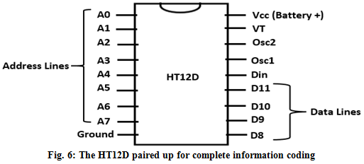 Figure 6. The HT12D paired up for complete information coding
The address line is used to direct data from the encoder to travel to a specific decoder. When using a single pair of encoder-decoder IC, the address pins are usually left unconnected. But if there is more than one decoder but only single encoder, it is necessary to give an address to the data that it might travel to specific decoder only and the data should not leak at unnecessary decoders. This is useful for the security of our data.
The HT12E discussed above provides only four inputs, for remote control application. This limits the number of devices that can be controlled. The 74147 in another encoder, which encodes 10 – Line Decimal information to 4 – Line Binary Coded Decimal (BCD) information [14]. This IC is a multiplexer as it allows ten (10) inputs and gives out four (4) outputs which correspond to the input of the HT12E where the outputs of 74147 is connected [13, 14]. The logic circuit is as shown in Figure 7 and the truth table is as shown in Table II.
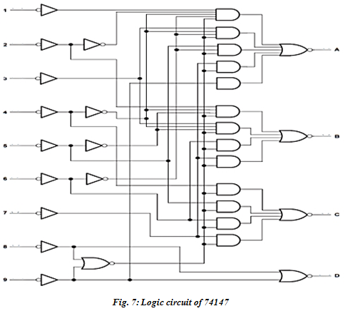 Figure 7. Logic circuit of 74147
Table II. Truth table of 74147
| INPUTS | OUTPUTS | |||||||||||
| 1 | 2 | 3 | 4 | 5 | 6 | 7 | 8 | 9 | D | C | B | A |
| H | H | H | H | H | H | H | H | H | H | H | H | H |
| X | X | X | X | X | X | X | X | L | L | H | H | L |
| X | X | X | X | X | X | X | L | H | L | H | H | H |
| X | X | X | X | X | X | L | H | H | H | L | L | L |
| X | X | X | X | X | L | H | H | H | H | L | L | H |
| X | X | X | X | L | H | H | H | H | H | L | H | L |
| X | X | X | L | H | H | H | H | H | H | L | H | H |
| X | X | L | H | H | H | H | H | H | H | H | L | L |
| X | L | H | H | H | H | H | H | H | H | H | L | H |
| L | H | H | H | H | H | H | H | H | H | H | H | L |
The HT12E encodes a 4 – line BCD information which is transmitted to the HT12D which decodes the 4 – line BCD information to give 4 outputs through the four output pins. The 74138 is a 3 – Line to 8 – Line Decoders/Demultiplexers which allows 3 inputs to give out 8 outputs [15]. It only takes three of the HT12D outputs and demultiplexes it to eight outputs allowing the control of eight appliances. The internal circuitry is a logic circuit comprising of AND, OR and NOT gates as shown in Figure 8 and the truth table is as shown Table III [15].
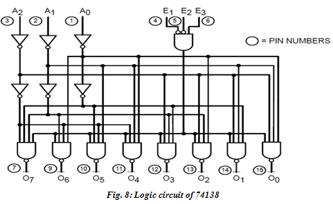 Figure 8. Logic circuit of 74138
Table III. Truth table of 74138
| INPUTS | OUTPUTS | |||||||||
| A0 | A1 | A2 | Y0 | Y1 | Y2 | Y3 | Y4 | Y5 | Y6 | Y7 |
| L | L | L | L | H | H | H | H | H | H | H |
| H | L | L | H | L | H | H | H | H | H | H |
| L | H | L | H | H | L | H | H | H | H | H |
| H | H | L | H | H | H | L | H | H | H | H |
| L | L | H | H | H | H | H | L | H | H | H |
| H | L | H | H | H | H | H | H | L | H | H |
| L | H | H | H | H | H | H | H | H | L | H |
| H | H | H | H | H | H | H | H | H | H | L |
This IC is a flip flop built with two independent J-K flip-flops with individual J-K, clock, preset and clear inputs [16]. Its function table is as shown in Table IV.
Table IV. Function table of 7476
| INPUTS | OUTPUTS | |||||
| CLK | J | K | Q | |||
| L | H | X | X | X | H | L |
| H | L | X | X | X | L | H |
| L | L | X | X | X | H | H |
| H | H | ↓ | L | L | ||
| H | H | ↓ | H | L | H | L |
| H | H | ↓ | L | H | L | H |
| H | H | ↓ | H | H | TOGGLE | |
| H | H | H | X | X | ||
This IC can be connected in the toggle mode such that when it detects a negative edge trigger in the clock input, it toggles the state of the output from high to low or vice versa.
This RF module comprises of an RF Transmitter and an RF Receiver. The transmitter/receiver (Tx/Rx) pair operates at a frequency of 434MHz [17]. An RF transmitter receives serial data and transmits it wirelessly through RF through its antenna connected at pin 4. The transmitted data is received by an RF receiver operating at the same frequency as that of the transmitter. In this RF system, the digital data is represented as variations in the amplitude of carrier wave. This type of modulation is known as Amplitude Shift Keying (ASK). The RF transmitter and receiver are shown in the Figure 9 [17].
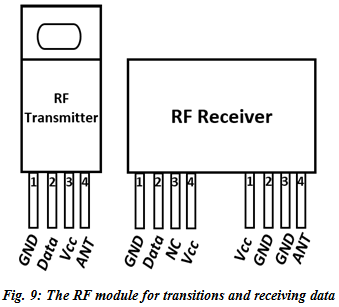 Figure 9. The RF module for transitions and receiving data
The RF transmitter transmits any data fed into the data pin (pin 2) through the antenna connected at the antenna pin (pin 4). The receiver receives any data transmitted on its frequency through the antenna connected at the antenna pin (pin 8) and puts the data out through the data pin (pin 2).
This IC is a voltage regulator, it has three pin outs: the input voltage pin, the ground pin and the output voltage pin. When a voltage greater than 5V is applied through the input pin, and the ground pin connected to the ground of the voltage source, the output pin gives out a voltage of +5V. From the name 7805, the “78” indicates that it is a positive voltage regulator, and the “05” indicates that it is a 5V regulator. With the help of this IC, positive power supply of 5V is achieved.
3. Design and Development of the System
The design method is as follows:
- Component specifications are as shown in Table V.
Table V. Components specification
| COMPONENTS | VOLTAGE (V) | CURRENT (mA) |
| Transformer | 12 | 1000 |
| Bridge rectifier | 200 | 6000 |
| HT12E | 5 | 0.5 |
| HT12D | 5 | 0.5 |
| 7805 | 5 | 5 |
| 7812 | 12 | 5 |
| 74138 | 5 | 5 |
| 74147 | 5 | 5 |
| 7476 | 5 | 5 |
| BC548 | 5 | 5 |
| Relay | 12 | 30 |
| RF transmitter module | 5 | 5 |
| RF receiver module | 5 | 5 |
- The system mainly comprises of two parts: the transmitter, and the receiver. The transmitter stands alone and makes use of power supply from a cell. It comprises of the input system, multiplexers and modulator. The receiver on the other hand comprises of the demodulator, demultiplexers, flip flops and control relays. The receiver section circuitry is divided into three sections: the power supply circuitry, the signal receiving circuitry and the switching circuitry.
3.1. The Transmitter circuit design
The transmitter section consists of the following components: Battery, 7805, 10µF capacitor (x2), 1KΩ resistor (x6), 74LS147, push button (x5), HT12E, ASK RF module transmitter. The transmitter section is powered by a 9volts battery. Due to the specifications of the components of the transmitter, 5 volts is required to power the ICs. This led to the voltage regulation by the use of the voltage regulator 7805, which regulates the 9 volts to 5 volts. This regulated voltage powers the whole transmitter section circuitry.
The input pins of the 74LS147 which is a multiplexer is connected to the voltage source to make the pins logic one (1 – high). These pins are connected through resistors functioning as current limiting resistors. These resistors limit the current into the 74LS147 through the following analysis. The resistors R1 to R5 are the current limiting resistors. The IC 74147 requires a current of 5mA and from the relation. The resistor calculation is shown in equations 1 and 2.
Therefore, resistors R1 to R5 with value of 1kΩ each limit the current into the IC 74147 to 5mA.
The input pins of the 74LS147 each is connected through a push button to the negative terminal of the battery. This is to provide logic zero (0 – low) to the IC when switched. When the button is pressed, the output pins changes as provided in the truth table of Table II. For this work, the control is for five appliances only. Pins 4, 3, 2, 1, 13 of the 74LS147 are used. When the buttons to these pins are switched independently, the output pins give logic output as analyzed in the Table VI.
Table VI. IC 74LS147 signal multiplexing function
| Pin | Button pressed | Input | Output |
| 4 | B1 | XXXXXXLHH | LLLH |
| 3 | B2 | XXXXXLHHH | HLLH |
| 2 | B3 | XXXXLHHHH | LHLH |
| 1 | B4 | XXXLHHHHH | HHLH |
| 13 | B5 | XXLHHHHHH | LLHH |
The binary equivalent of these outputs LLLH, HLLH, LHLH, HHLH, and LLHH is 0001, 1001, 0101, 1101, and 0011 respectively. This output of 74LS147 is fed to the input of the HT12E. The HT12E is a parallel data to series data encoder; it encodes the parallel data inputs (the output of 74LS147) that it receives from 74LS147 to a series data that it sends out through the Data out pin (pin 17). The encoding function of the HT12E gives an instance input of binary 1001 as shown in the Figure 10 [18].
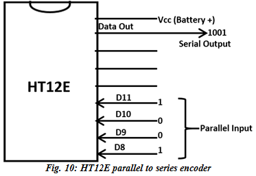 Figure 10. HT12E parallel to series encoder
The serial output of the HT12E is transmitted to the RF module. The ASK RF module operates at a frequency of 434MHz, and transmits data that it receives using the radio frequency medium through the antenna connected at the antenna pin. The velocity of the transmitted data is the velocity of free space.
This implies that the wavelength (λ) of the transmitted data is 69cm.
3.2. The Receiver circuit design
The receiver section has three sections that work together to receive and process the received signal and carry out a switching operation. These sections include: the power supply and the control section.
3.2.1. The power supply
The power supply comprises of the following components: 220/12V transformer, bridge rectifier, capacitors, 7805, 7812 and AC plug. The power supply provides the voltages required by the ICs for proper operation. It involves the rectification of AC voltage to DC and the regulation of this DC to a voltage as required by the ICs. The transformer steps down the AC voltage to 12 volts, the bridge rectifier carries out a full wave diode rectification to give an output voltage as analyzed from equations.
Peak value of the output voltage:
This output voltage across the capacitor is regulated by the voltage regulator 7805 to give a +5V, and the 7812 also regulates this voltage to give a +12V. This makes available three terminals for 5V, 12V and ground respectively.
3.2.2. The control section
This section carries out the control of household appliances. It is responsible for receiving the signal from the transmitter, processing this signal and switching “ON” or “OFF” an appliance. It comprises of the following components: HT12D, 74138, 7476 (×3), resistors (1KΩ ×7), transistors (BC548 ×5), diodes (1n4001 ×5), ASK RF module receiver and relays (×5).
The ASK module receives signals transmitter at a frequency of 434MHz from the transmitter, it sends this signal out through its data pin (pin 2) to the data-in pin (pin 9) of HT12D. The ASK module operates with a voltage of 5 volts and a current of 5mA, this gave rise to a current limiting resistor connected to the voltage input of this module whose value is as calculated in equation 10.
The HT12D is a series to parallel data decoder which decodes the serial binary data. It receives from ASK module to parallel data and gives out this parallel data through its output pins, pins 12, 13, 14, 15. It gives out a “high” for binary one (1) and a “low” for binary zero (0) which is 5 volts and 0 volts respectively. An instance is given in the Figure 11 for when the HT12D receives a binary input of “1001” from the ASK module.
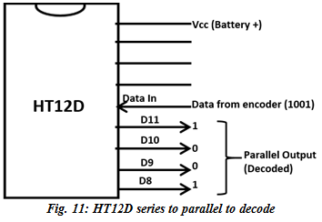 Figure 11. HT12D series to parallel to decode
The data decoded by the HT12D is a multiplexed data from the IC 74LS147 encoded by HT12E. This data decoded by HT12D, needs to be de-multiplexed. The output of this HT12D is therefore fed transmitted into the input pins of the IC, 74LS138. The 74138 is a 3 – Line to 8 – Line Decoders/De-multiplexer which allows 3 inputs to give out 8 outputs. It only takes three of the output pins of HT12D as input and de-multiplexes it according to the signal output of Table VI as shown in the Table VII.
Table VII. IC 74LS138 signal de-multiplexing function
| HT12D Output | 74LS138 Input | Output | Pin triggered |
| LLLH | LLL | LHHHHHHH | 15 |
| HLLH | HLL | HLHHHHHH | 14 |
| LHLH | LHL | HHLHHHHH | 13 |
| HHLH | HHL | HHHLHHHH | 12 |
| LLHH | LLH | HHHHLHHH | 11 |
The Table VII shows that when button to pins 4, 3, 2, 1, 13 of the IC 74LS147 of the transmitter is pressed, pins 15, 14, 13, 12, 11 of the IC 74LS138 of the control section is triggered from “high” to “low” (5 volts to 0 volts). These output pins of the 74LS138 each is fed into a flip-flop. The IC 7476 is a flip flop built with two independent J-K flip-flops with individual J-K, clock, preset and clear inputs. With the five outputs of the 74LS138, three of the IC 7476 is required. The flip flop is configured in a toggle mode such that when the clock input receives a negative shot trigger, the output is toggled. With this configuration of the flip-flop, when a button is pressed, the output of the flip flop will be “high” (5 volts), when the same button is pressed again, the same output goes “low” (0 volts).
The outputs of the flip flops each is fed to the base of a transistor, BC548. The application of this transistor is for switching. When the output of the flip flop is high, the voltage at the base of the transistor becomes 5 volts, this biases the transistor and allows current to flow from the collector to the emitter. When the output of the flip flop is low, the voltage at the base of the transistor is 0 volts and thereby not biased, current will not flow to the emitter from the collector. A resistor is used at the base of the transistor to limit the current to the required base current of 5mA. The value of this resistor is calculated from equation 3.10. A relay is connected at the collector of the BC548 and 12volts power supply as the relay is rated 12volts. The normally connected and the normally open terminals of the relay are connected to the switching terminals of the two-way switch which is used to achieve double control; manual and remote control. The AC life terminal is connected to the control terminal of the two-way switch, and the neutral connected to the load. The second terminal of the load is then connected to the control terminal of the relay. When the relay and the two-way switch are switched to one path, the connected load is turned on, when the relay and the two-way switch is switched to different path, the load is turned off. In this case, either of the relay or the manual switch can be used to turn on or off the connected load.
- The Security Design
The security design of the system comprises of additional circuitry added to both the transmitter and the receiver sections. It makes the receiver able to receive signal from the transmitter only when a condition set in the receiver is met on the transmitter. The circuit consists of push buttons connected to the address pins of the IC HT12E for the transmitter section and also push buttons connected to the address pins of HT12D for the receiver section.
Transmission of signal from the transmitter to the receiver is only possible when the address line of the transmitted signal is the same with the address line of the receiver system. Exploring this, the push buttons in the receiver section are used to pre-set some pins as desired by the user to logic zero. The user of the transmitter must set similar pins on the transmitter section to logic zero before transmission will be possible. With this, only the user who knows the preset pins in the receiver can set the transmitter to transmit signal to the receiver.
4. The Simulation of the project
Computer aided simulation of the project was carried out using a computer software called proteus. With proteus the project circuits were implemented by selecting various components of the design and interconnecting these components as regards to the project design.
4.1. Implementation of the circuit on a temporary board
Implementation of the circuit on a temporary board is for clarification purposes and testing of components reliability and functionality. The project design was carried out on a temporary board to ensure proper connection for testing as shown in Figure 12.
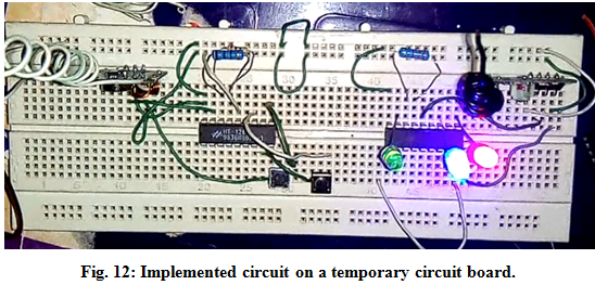 Figure 12. Implemented circuit on a temporary circuit board
On the temporary project board, signals sent through the transmitter by pressing push buttons on the board were transmitted to the receiver and the action caused the switching on and off of an LED connected at the output section of the receiver. The result from test-running the circuit on the bread board was positive.
4.2. Construction on a permanent board
Subject to the positive result from the test on a temporary project board, implementation of the circuit on a permanent circuit board was carried out. This implementation involves the soldering of the components to the board, and carrying out appropriate connections of the components. The components were arranged on the circuit board following the specification of the circuit design. The construction of the work on the permanent circuit board (Vero board) is as shown in Figure 13 to Figure 17.
4.3. Testing
The testing of the circuit design was carried out while the project was implemented on the permanent circuit board. After soldering the power supply circuit on the receiver section, this power supply was tested to ensure that it gives the expected voltage of +5V and +12V and it tested positive. At completion of the construction of the transmitter and receiver section, an LED was connected to the TE pin out of the HT12D, whenever transmission is possible between the transmitter and the receiver, this LED will be on; with this, monitoring effectiveness of signal transmission was possible. When the implementation was complete, the project was equally tested to ensure that it is working. For the range of operation, the transmitter was moved away from the receiver while transmitting signals to estimate the distance for operation. The estimated range of operation of the project was within one hundred meters (100m).
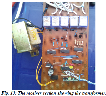 Figure 13. The receiver section showing the transformer
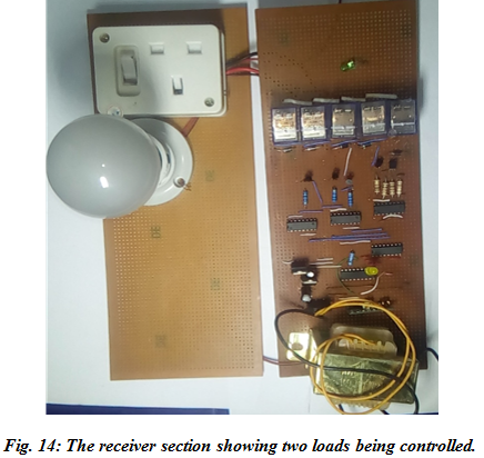 Figure 14. The receiver section showing two loads being controlled
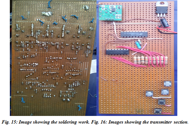 Figure 15. Image showing the soldering work Figure 15. Image showing the soldering work |
4.4. The Engineering measurement and evaluation bill
The bill of engineering measurement and evaluation for the project is given as shown in Table VIII.
Table VIII. Bill of Engineering Measurement and Evaluation
| MATERIAL | QUANTITY | COST (Naira) |
| HT12E and HT12E | 1 each | 150 each |
| RF MODULE | 1 | 2000 |
| 74147 and 74138 | 1 each | 100 each |
| 7476 | 3 | 150 |
| BC548 | 5 | 100 |
| BUTTON | 15 | 150 |
| DIODE (1N4001) | 5 | 50 |
| RELAY | 5 | 250 |
| RESISTORS | 11 | 220 |
| 7805, 7812, BATTERY & RECTIFIER | 1 each | 50 each |
| TRANSFORMER | 1 | 500 |
| CAPACITORS | 2 | 60 |
| Packaging | ———- | 700 |
| TOTAL | 4880 |
4.5. Analysis and Results
When the transmitter is powered, a voltage of 5volts is impressed on the pins 11, 12, 13, 1 and 2 of the IC74147. With the resistors (1 kΩ each) in series to these pins, a current of 5 mA flows through each of these pins. When the button to a pin is pressed, a zero voltage (0 volts) is impressed to the pin and no current flows through the pin of the IC. This leads to series of signal processing within the circuit as analyzed in Table IX.
Table IX. Analysis of signal transmission
| Transmitter | Receiver | ||||
| Button Pressed | 74147 Input | HT12E Input | HT12D Output | 74138 Output | Load Triggered |
| B1 | XXXXXXLHH | LLLH | LLLH | LHHHHHHH | Load 1 |
| B2 | XXXXXLHHH | HLLH | HLLH | HLHHHHHH | Load 2 |
| B3 | XXXXLHHHH | LHLH | LHLH | HHLHHHHH | Load 3 |
| B4 | XXXLHHHHH | HHLH | HHLH | HHHLHHHH | Load 4 |
| B5 | XXLHHHHHH | LLHH | LLHH | HHHHLHHH | Load 5 |
From Table IX, a button pressed in the transmitter causes a logic signal transmission from the input of 74147 to the out of 74138 which triggers a load as in the table. The analysis of voltages, resistance values in the circuits are shown in equations 1 to equation 10 and the packaged completed project of an example has been developed for controlling two lighting points and having three socket outlets for the proposed appliances: a refrigerator, water heater and an air conditioner as shown in Figure 17.
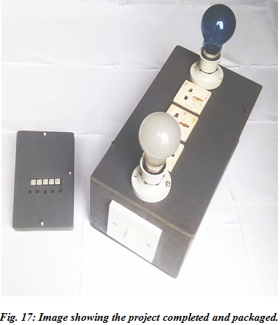 Figure 17. Image showing the project completed and packaged
Remote controls developed with the technology of Infrared can only transmit signal within line of sight. This project transmits signal through obstacles on the line of sight. Other works with similar transmitting technology of Radio Frequency can be manipulated and controlled with any device transmitting signal on the same frequency. This project has security feature which states that the receiver can only receive signal from a transmitter carrying signal with the same signal address by the receiver.
5. Conclusion
Remote control is very important in household application, it brings about comfort when controlling and operating household appliances. It makes life easy while trying to make switching operation of appliances. In this work, the design and construction of a remote control for household application has been achieved. A transmitter system (the handheld remote), which comprises of encoder, multiplexer, RF module, push buttons, etc. has been developed which when operated, sends a signal to the receiver system. This receiver system receives and processes the signal from the transmitter, then turn ON or turns OFF an appliance. The receiver system which comprises of decoder, de-multiplexer, flip-flops, transistor, relays etc. has also been developed which when receiving signal from the transmitter processes of the signal, switches ON or switches OFF a load. Incorporating a security system, allows transmission of signal only when certain conditions are met, thereby providing security for household appliances and the aim achieved.
- A. Roy Delgado, R. Picking and V. Grout, “Remote-Controlled Home Automation Systems with Different Network Technologies”, University of Wales, Wrexham, UK, 2013.
- Abdulaleem A. Rasheed, “Detection and study of various IR handheld remote control signals and using them for home applications”, IEEE Conference on Education and e-Learning Innovations (ICEELI), Sousse, 2012.
- C. Woodford, “How remote control and radio control work”, 8 September 2015 [Online].Available:http://www.explainthatstuff.com/remotecontrol.html. [Accessed 9 April 2016].
- N. Neil, “Wikipedia, the free encyclopedia”, 7 April 2016. [Online]. Available: https://en.wikipedia.org/wiki/Remote_control. [Accessed 9 May 2016].
- M. M. Ahmed, E. Ahmed and K. T. Ahmmed, “Automated Irrigation Control and Security System with Wireless Messaging”, 2013 International Conference on Informatics, Electronics and Vision (ICIEV), Dhaka, 2013, pp. 15. doi: 10.1109/ICIEV.2013.6572595
- L. Jianjun, Li Zhishu and M. Mingyi, “A New USB Home Appliances based on PC and Infrared Remote Control Protocol”, IEEE 2010 International Conference on Computer and Communication Technologies in Agriculture Engineering, Chengdu, 2010.
- L. Chen, Z. Wang, J. Chen, Li Fule, H. Wenhan, B. Xiao, C. Zhang and W. Zhihua, “A RF Remote-Control Transceiver with Zero-Standby Power Based on RFID Technology”, IEEE 2010 Asia Pacific Conference on Postgraduate Research in Microelectronics and Electronics (PrimeAsia), Shanghai, 2010.
- C. Gang, X. Tiefeng, L. Taijun, Yan Ye, X. Gaoming, “A GSM-based wireless remote controller”, IEEE 2011 International Conference on Electronics, Communications and Control (ICECC), Zhejiang, 2011.
- Md. Shariful Islam, Md. Badsha Mia, Kazi Tanvir Ahmmed, “Wireless Remote Switching System for Controlling Devices with an Algorithm based DTMF Detection”, IEEE 2014 International Conference on Electrical Engineering and Information and Communication Technology (ICEEICT), Dhaka, 2014.
- Liu Wei, Jiang Wenlong, Gao Yonghui, Ren Tao, “Remote Control of Smart Household Based on DTM”, IEEE 2010 2nd International Conference on Advanced Computer Control (ICACC), Shenyang, 2010.
- A. J. A. Mghawish, “A Practical Approach for Mobile-Based Remote Control”, European Scientific Journal of European Scientific Institute, ESI, vol. 9, no. 18, pp. 194-201, 2013.
- Cornell, “HT12A/HT12E – Series of Encoders Datasheet”, [Online]. Available:https://people.ece.cornell.edu/land/courses/ece4760/FinalProjects/s2008/cl457_yft2/cl457_yft2/datasheets/HT12E.pdf. [Accessed 13 May 2016].
- Farnell, “HT12D/HT12F 2 Series of Decoders Datasheet”, [Online]. Available: www.farnell.com/datasheets/1525377.pdf. [Accessed 12 May 2016].
- T. Instrument, “SN74147 10-Line to 4-Line BCD Priority Encoder – Datasheet”, [Online]. Available: http://www.ti.com/lit/gpn/sn74147. [Accessed 11 May 2016].
- T. Instruments, “74138 3-Line To 8-Line Decoders/Demultiplexers – Datasheet”, [Online]. Available: www.ti.com/lit/ds/symlink/sn74ls138.pdf. [Accessed 11 May 2016].
- T. Instrument, “SN7476 Dual J-K Positive-Edge-Triggered Flip-Flops with Preset and Clear – Datasheet”, [Online]. Available: http://www.ti.com/lit/gpn/sn7476. [Accessed 12 May 2016].
- WENSHING, “Wireless Hi Power Transmitter and Receiver Module – Datasheet”, [Online]. Available:http://cdn.sparkfun.com/datasheets/Wireless/General/TWS-BS-3_433.92MHz_ASK_RF_Transmitter_Module_Data_Sheet.pdf. [Accessed 12 May 2016].
- Pingjun Wei, Xiaojing Li, Zhoufeng Liu and liangbo Zhu, “Design of Intelligent Control System of Eight-Way Wireless Remote Control Crane Based on RF Technology”, IEEE 2012 International Conference on Advanced Mechatronic Systems, Tokyo, 2012.