Simulation and Implementation of Sensorless Control in Multi-Motors Electric Drives with High Dynamics
Simulation and Implementation of Sensorless Control in Multi-Motors Electric Drives with High Dynamics
Volume 2, Issue 4, Page No 59-67, 2017
Author’s Name: Marcel Nicola1, a), Dumitru Sacerdotianu1, Claudiu-Ionel Nicola1, Adrian Hurezeanu1
View Affiliations
1 Research and Development Division, National Institute ICMET Craiova, 200746, Romania
2Research and Development Division, CESI Automation Craiova, 200746, Romania
a)Author to whom correspondence should be addressed. E-mail: marcel_nicola@yahoo.com
Adv. Sci. Technol. Eng. Syst. J. 2(4), 59-67 (2017); ![]() DOI: 10.25046/aj020409
DOI: 10.25046/aj020409
Keywords: Sensorless control, Multi-motors, Electric drives

Export Citations
In this article we’ll tackle the control of multi-motors electric drives with high dynamic, with rapid changes in torque and speed, with rigid or flexible coupling of motors, where the control strategy is FOC (Field Oriented Control) for each drives and the distributed control in local network using the CANopen protocol. In the surface mining industry, from which the electric drive application for this article is selected, the general trend is toward using asynchronous motors with short-circuit rotor, due to the advantages of this motor both in terms of design and operation. In order to achieve the variable speed, must be used the static frequency converters with sensorless control, where speed is estimated using a Model References Adaptive Control Estimator. The global control system proposed in this paper contain this type of MRAC estimator together with PI-control based, who ensures a good dynamic performance but in a lower complexity of structure such that are properly to implement in real time in a distributed control system with DSP in local network using the CANopen protocol with advantages in terms of software technology, as well as control cost and flexibility of use. Following these directions a functional application was implemented and tested in practice.
Received: 04 April 2017, Accepted: 05 May 2017, Published Online: 17 May 2017
1. Introduction
This paper is an extension of work originally presented in International Conference on Applied and Theoretical Electricity (ICATE) 2016 [1].
Electric drives represent complex equipment designed to ensure optimal power supply and command of actuators during the operating processes. The development of electric drive systems was characterized in recent years by a special dynamic, linked both with technological advancements in the manufacture of semiconductor switching elements and new topologies of electric drive [2–6].
To study the behavior of the system of frequency converter plus motor prior to the actual construction of the converter, a series of numerical simulations have been carried out using MATLAB/Simulink environment. Trial and error type iterations are necessary to avoid the rough design errors, but also to identify a series of complex effects and phenomena, even if in the simulated environment, which should converge towards a positive purposefulness of the whole project. We are showing the control of electric multi-drive with high dynamic, with rapid changes in torque and speed, with rigid coupling of motors where the control strategy is FOC for each drives, sensorless control, where speed is estimated using an Estimator. Simulations were carried out in MATLAB/Simulink environment, highlighting the control structures, and the tuning parameters for a multi-drive application commonly used in surface mining industry. Sensorless control has a lot of advantages in terms of software technology, as well as control cost and flexibility of use. Therefore, the main function of the control subsystem is prediction of speed. Fortunately, achievements in control theory, such as Kalman or Luenberger estimators, have largely contributed to solving this problem. This emphasizes the importance of continuous migration of new approaches and achievements in control theory to the field of electric drives.
From these reasons, in this article we will focus on observer, namely a MRAC-Model References Adaptive Control [12,18]. Although it doesn’t have the advantage of the Kalman type estimator (which provides a good prediction even for additional uncertainty added to the measured values), this estimator has the advantage of simplicity in terms of its structure, because obviously beside the simulations which ensure a good design, it also performs the implementation of algorithms for measurement, control and prediction in a DSP, where the number of variables and performed operations must be optimized [19].From point of view of control of overall system, active research area include sliding mode control [7,8], model predictive control [9–11], adaptive control, [12,13] and their references, I/O feedback linearization [14], robust control [15], artificial neural networks and fuzzy control [16,17]. In [2,8,9] a set of observers are analyzed like: super–twisting observer, an observer based on generalization of the phase locked–loop technique, a simple Luenberger observer, full order and reduced order adaptive system. The conclusion is that in general, these control schemes yield satisfactory results, as verified by numeric simulations and real–time experiments, making difficult to decide which sensorless control scheme performs better (in reasonable requirements of precision, like an industrial application).
The overall control system is distributed around a local network using the CANopen protocol [20]. The multi-motor control system can drive motors with rigid or flexible coupling with rated output power between 45 kW and 75 kW, using same hardware and specifically software, but in commissioning phase, the system make an automatically dynamic identification of electrical and mechanical motor parameters. After that before each starting a static identification of motor is performed and from internal database of each DSP are selected the optimal parameters for each regulators.
We start the simulations and implementation of the functional application from this paper, with the results presented in [1,21] were the speed is measured directly with an encoder, compared with the case of sensorless control.
The functional device for driving complex multi-motor applications has the following features: driving under acceleration and braking of two (to six) engines; using the common DC bus; braking power is provided with inverter for braking energy recovery in industrial electrical network; operates in master-slave mode with vector control method; no need for various transducers: motion, position, speed, etc.
The functional model has the advantage of using a drive scheme in which independent drives will have one DC intermediate circuit properly sized. Also, a significant breakthrough in independent electrical drives is the uses of a single inverter in the network recover braking energy, while the actuators (motors) have different characteristics. Such equipment is used in applications where multiple motors are required to achieve the necessary torque or synchronous speed, such as: industrial machinery and large excavators; conveyor unit; electric traction vehicle (tram, metro); railway electric traction; cement mills, coal mills. The proposed functional model will perform and recover braking energy of each motor in the electrical network. The functional model from this paper was tested in practice for a long time period with good results.
The structure of the paper is as follows. In second section will briefly present the basics of Field Oriented Control for the induction motor and the simulations performed in sensorless control. In section 3 are presented the control strategy master-slave and the simulations in multi-motors electric drives. Section 4 show the practical implementation of the control structures from previous sections, and the experimental setup and results are presented. Finally, some conclusions will be issued and will be pointed out some ideas for continuation of work.
2. Sensorless Control of Electric Motor Drives
The technical data of each electric drive (master and slave) system, used for simulations, which includes static frequency converter designed with superior technical features providing speed regulation between zero and the rating value for induction motors with short-circuit rotor, are as follows: supply voltage: 3 x 400 Vac/50 Hz; rated output power: 45 kW; peak output: 1.5 x PN/2 minutes; operating temperature: -25°C to 45°C. The nominal parameters of each motors used in simulations are given in the below Table.
Table: Nominal parameters of motor.
| Parameter | Value | Unit |
| Power | 51136 | VA |
| Voltage | 400 | Vrms |
| Frequency | 50 | Hz |
| Stator resistance – Rs | 0.041 | W |
| Rotor resistance – Rr | 0.05 | W |
| Leakage inductance stator – Ls | 0.0008 | H |
| Leakage inductance rotor – Lr | 0.0008 | H |
| Mutual inductance stator – Lm | 0.0207 | H |
| Rotor values – Inertia | 3.1 | kg·m2 |
| Rotor values – Friction | 0.1 | N·m·s |
| Pole pairs – p | 2 | – |
| Snubbers resistance | 104 | W |
| Snubbers capacitance | 20*10-9 | F |
| Diodes On-state resistance | 0.001 | W |
| Diodes Forward voltage | 1.3 | V |
| DC Bus Capacitance | 8400*10-6 | F |
| Breaking chopper resistance | 8 | W |
| Breaking chopper frequency | 4000 | Hz |
| Breaking chopper activation voltage | 750 | V |
| Breaking chopper shutdown voltage | 650 | V |
| Machine Flux | 0.73 | Wb |
| Speed ramp (acceleration) | 150 | rpm/s |
The model Simulink for the sensorless version is shown in Figure 1, [18]. In the following simulations, the behavior of the converter unit plus motor will be analyzed, in terms of the following quantities: stator current, rotor speed, torque and voltage in the intermediate circuit.
The classic form in s domain of a PI controller is:
![]() where is the proportional term and is the integral term. For the Simulink implementation we have the equivalence [18]:
where is the proportional term and is the integral term. For the Simulink implementation we have the equivalence [18]:
![]() where is the proportional gain and is the integral gain.
where is the proportional gain and is the integral gain.
The varying parameters were: for the speed regulator Kp and Ki, for the flux controller Kp and Ki, speed ramps and the hysteresis band for the current regulator. In addition with the encoder case, the estimator which is implemented around a PI controller will also have tuning parameters Kp and Ki. The PI controllers tuning was carried out using the parameters and discrete models presented in Simulink [18]. The model Simulink is show in Figure 1, the interface for parameterization of the motor is shown in Figure 2 and the interface for the parameterization of the rectifier, inverter, intermediate filter and braking chopper is shown in Figure 3.
The chosen vector control mode is of FOC type, and the parameterization of speed regulators, flow controllers, current regulators, acceleration/braking ramp, filters and limitations is shown in Figure 4. Figure 5 show the general control diagrams of speed controllers, current and flux controllers, the transform of coordinates and calculation of the rotor position for FOC control strategy implemented in Simulink.
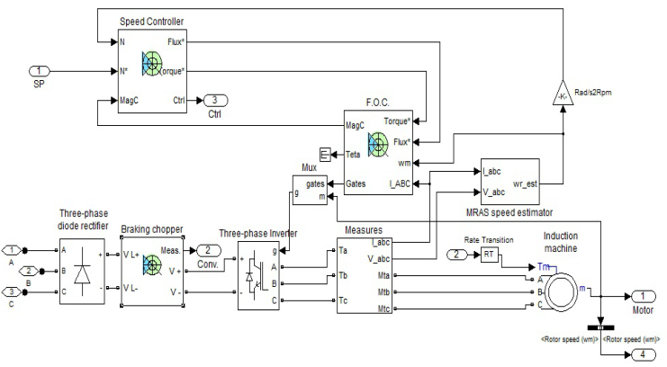 Figure 1. Simulink block diagram for sensorless model.
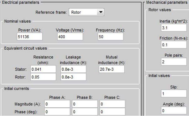 Figure 2. Interface for Parameters of motor.
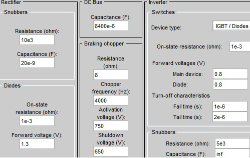 Figure 3. Interface for Parameters of Rectifier, DC Bus and Inverter.
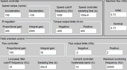 Figure 4. Interface for adjustable parameters of the controllers.
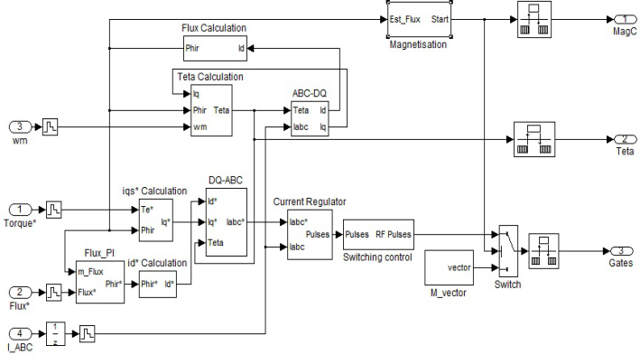 Figure 5. Field Oriented Control block diagram.
The output of speed controllers supply the electromagnetic torque (T*) and flux (Phi*) references for inner loop control. Following [18] and Figure 5 for usual electrical parameters given above we can write the equations and transfer functions for calculate the Id, Iq and the intermediate value of flux used at each iteration by de FOC strategy control in rotor reference frame.
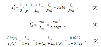 where the symbol * mean that the value is calculated and will be used to the next iteration. In this way we can write the equations for each block from Figure 5.
The type of estimator for angular speed is MRAC (see Figure 6). The equations of Blocks A and B are [12]:
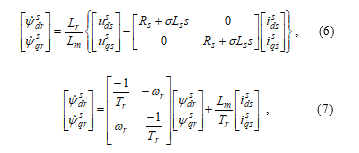 For the speed Estimator implemented in Simulink, let note
and starting with equations [12,13] we obtain:
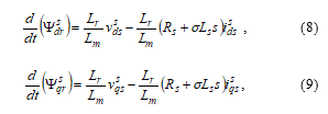
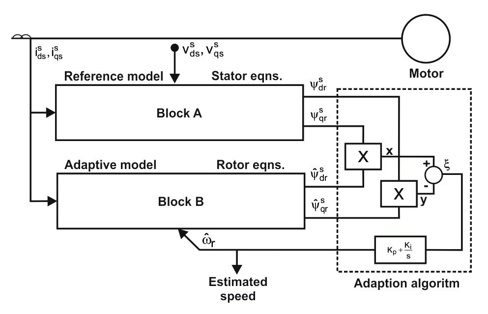 Figure 6. Speed estimator block diagram.
The encoder is thus eliminated, and the angular speed is estimated from current and voltage measurements. Using Popov hyperstability criterion, in order to achieve the overall asymptotic stability, an estimator will be achieved as follows [12]:
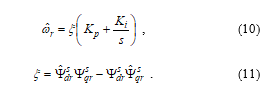 In FOC control strategy (see Figure 1 and Figure 5) the flux and current controllers are in inner loop and the speed controller is in outer loop control. Because the speed estimator must operate faster than the outer control loops, we choose considerably lowering the tuning values for the speed regulator (so that they will be much smaller than the values of the controller from the estimator), and the optimum tuning is achieved even for an increasing dynamic of the references torque and speed like in the next set of parameters (see Figure 7):
Set of parameters no.1: Speed controller: Kp=30, Ki=20; Flux controller: Kp=100, Ki=3, hysteresis band of current controller=10A; speed estimator controller: Kp=500, Ki=5000; the speed reference is given by the sequence: [0 0.5 2 4 7 8 9]sà [0 150 300 500 350 450 700]rpm; the torque reference is given by the sequence: [0 3 6 9 10]sà [10 100 200 300 100]Nm.
The controllers have a good tuning even for a fluctuation of 100% in rotor resistance and for regenerative braking. Besides the good dynamic performance are achieved (stationary error, settling time, rising time, overshooting and oscillation index), due to proper tuning of the regulators PI using Ziegler-Nichols method [9] and varying the hysteresis band of current controller between 5A and 20A.
Using a quality index given by de sum of squared errors between desired speed and measured speed, after a lot of simulations the best tuning is achieved. Both in simulations and in implementation in DSP, a special attention is given to the phenomenon of saturation of component blocks. For the control loops, limiting and anti-windup components will be implemented in the PI controllers [1,18,21].
Because the influence of the tuning parameters of PI-controllers on the performance parameters is complex and somehow antagonist, trial and error type iterations are necessary when the Ziegler-Nichols method is used for tuning of each PI loop. For example increasing and then the stationary error and rising time are reducing but overshooting and oscillation index are rising. In practice depending on the application, the importance and the weights of the performance parameters is chosen.
In [9] are presented a set of applications where the control is predictive or PI-control based and are highlighted the advantages and disadvantages for each of them. Although the predictive control can be seen like a real time optimal control, for an induction motor with similar parameters with the above Table, in [11] is proved that dynamic performance are slightly reduced in comparison with PI-control based because of complexity of model and the controller. These can be seen like reasons for which we choose for the applications presented in this paper a PI-control based. This type of control together with MRAC estimator ensures a good dynamic performance but in a lower complexity of structure such that is properly to implement in real time in a distributed control system with DSP in local network using the CANopen protocol.
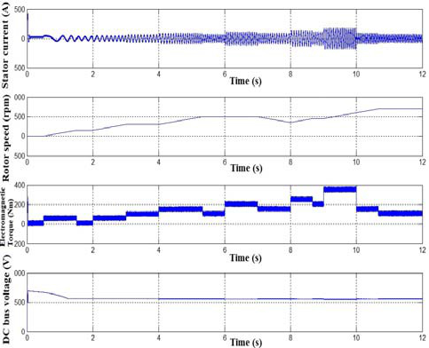 Figure 7. The simulation of sensorless model for the set no.1 of parameters of the controllers and references.
3. Multi-motors Electric Drives Control
The multi-motor applications require a synchronization of the inverters according to the type of the load and the interaction between the engines. An important feature of these applications is rigid mechanical characteristic kinematic chain as a whole. Between the electric motor and machine, there is only mechanical gear with fixed multiplication ratio. As a result, the complex drive equipment must ensure the following: equal or similar input frequency so to maintain maximum torque at each motor; frequency variation from minimum to maximum value; protection of electric motors in mechanical or electrical caused defects. In the multi-motor drives they are two essential conditions: kinematic chain and mechanical devices to be identical; mechanical characteristic of the electric motor to be more flexible. In practice, the first condition is very difficult to obtain due to operating conditions and mechanical wear, so these disadvantages should be directed to the second condition, namely the permanent and automatic adjustment of the electric motor, so it develops the needed torque at the imposed speed. The control system of the multi-motor drive includes a control system with FOC-type control strategy for each engine. One of the control systems will be considered as master and the other one as slave.
3.1. Rigid Coupling
In the case of rigid coupling of the two motors, they must have the same speed given the fact that the load torque on each shaft can be different. The drive speed reference will be set for the master system, and the output it controls (the master engine speed) will be transmitted as a speed reference for the slave system. In actual implementation this communication is achieved as CANopen protocol. In the simulations (see Figure 8) we added a delay block to catch the effect of delays in the transmission of the reference from the master system to the slave system and the way the overall drive control system behaves. The load torques in the driving axles may be different and are considered elements of disturbance for the driving system which must provide equal speeds for the two motors.
The control systems of each engine have been presented in previously section. From single-engine simulations optimal settings will be used for the control systems. In order to increase the speed of response for the slave system for tracking the master system, the acceleration/deceleration ramp was maintained at 150rpm/s for the master system and the acceleration/deceleration ramp was increased at 1000rpm/s for the slave system. This change has given good results in simulations, and will also be implemented in the DSP’s of the control systems of each engine.
 Figure 8. Simulink block diagram for multi-drives control.
Another way to increase the speed of response of the slave system was to increase the speed of response of the PI-type controllers in the slave control system by increasing the regulation parameters, but there has been no significant improvement, in addition there is the risk of overshooting in the local loops and the oscillation of the overall control loop. This alternative has not been accepted for implementation in the DSP’s.
As a result of simulations, it was concluded that the overall control system has better results for delays in the transmission of the reference from the master to the slave for values up to 5ms in case of maximum 20% torque imbalance, i.e. a distribution of 60%-40% for the two motors. In practical implementation, for safety reasons, the delay will be limited to 4ms by setting the reference through the local communication network CAN between the master and the slave DSP’s, using a communication method which is suitable for this time period. In practical implementation, the maximum permissible imbalance will be of 18% for the load torques, there will be a warning signal if this rating is exceeded, and the fault protection is set to a higher rating (depending on the beneficiary and the application). The quantities in question resulting from these simulations are for each master and slave subassembly: stator currents, electromagnetic torques and speeds. The voltage rating in the intermediate common DC circuit and the overall load torque in the rigid coupling shaft were achieved through simulations. We show the simulations for the next set of parameters.
Set of parameters no.1: Speed controller: Kp=30, Ki=20; Flux controller: Kp=100, Ki=3, hysteresis band of current controller=10A; speed estimator controller: Kp=500, Ki=5000; acc master=150rpm/s, acc slave=1000rpm/s, delay=4ms; the speed reference is given by the sequence: [0 0.5 2 4 7 8 9]sà [0 150 300 500 350 450 700]rpm; the torque distribution master-slave from load torque:[50% – 50%].
Set of parameters no.2: Speed controller: Kp=30, Ki=20; Flux controller: Kp=100, Ki=3, hysteresis band of current controller=10A; speed estimator controller: Kp=500, Ki=5000; acc master=150rpm/s, acc slave=1000rpm/s, delay=4ms; the speed reference is given by the sequence: [0 9]sà [700 900]rpm; the torque distribution master-slave from load torque:[0 3 6 9]sà [50-50 60-40 40-60 50-50]%.
In Figure 9 at second 7, when the load torque reference de-creases from 100Nm to 30Nm regenerative braking occurs and the voltage in the intermediate circuit increases. In Simulink, in order to analyze this phenomenon we have set the limits of the braking chopper between 750V (Activation Voltage) and 650V (Shutdown Voltage). For actual implementation, instead of the braking chopper, a regenerative inverter will be used.
In Figure 10 we observe that because the load torque is maximum 800 Nm, the master and slave have same speed with the reference just at low value. Between second 3 and second 6, because master has imposed 60% from load torque, the slave can follow the master but at speed less than the reference. At second 6 when the master has imposed 40% from load torque, the master can follow the speed reference, but not the slave. Starting with the second 11 when the imposed load torque is 50% for master and for slave, the speed of master and slave follow the speed reference. These simulations show that overall control system work well in limiting of saturation but evident in a practice situation from mechanical reason the protection must work immediately when the slave can’t follow the master. In Figure11 because the load torque doesn’t reach the saturation for same parameterization set, the slave and master follow the speed reference.
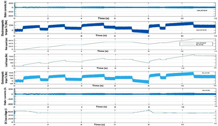 Figure 9. The simulation of master-slave drives model for the set no.1 of parameters of the controllers and references.
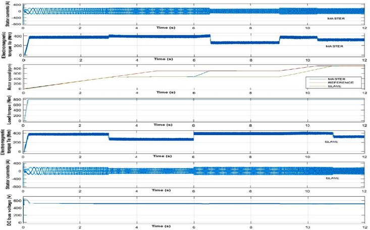 Figure 10. The simulation of master-slave drives model for the set no.2 of parameters of the controllers and references with saturation of load torque.
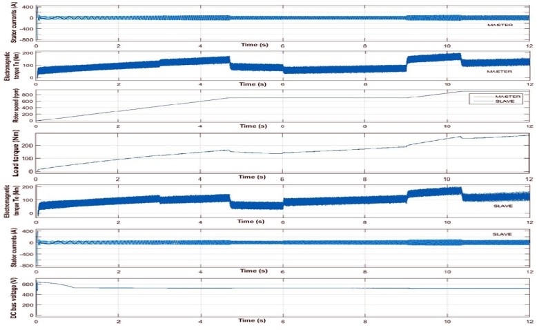 Figure 11 The simulation of master-slave drives model for the set no.2 of parameters of the controllers and references without saturation of load torque.
3.2. Flexible Coupling
In the case of flexible coupling of two or more motors, all motors must generate, as much as possible, the same torque. The load torques in the driving axles may be different and are considered elements of disturbance for the driving system which must provide equal electromagnetic torques for the two subsystems. The control system of the multi-motor drive includes a control system with FOC-type control strategy for each engine, but where the speed control loops are deactivated. One of the control systems will be considered as master and the other one as slave.
The drive motor torque reference will be set for the master system, and the output it controls (the electromagnetic torque) will be transmitted as a torque reference for the slave system. In actual implementation this communication is achieved as CANopen protocol. In the simulations (see Figure 12) we added a delay block to catch the effect of delays in the transmission of the reference from the master system to the slave system and the way the overall drive control system behaves. The control systems of each engine have been presented previously. From single-engine simulations optimal settings will be used for the control systems, except for the parameters of the speed control loop, which in this case is deactivated.
As a result of simulations, it was concluded that the overall control system has better results for delays in the transmission of the reference from the master to the slave for values up to 10ms, however in practical implementation, for safety reasons, the delay will be limited to 4ms by setting the reference through the local communication network CANopen between the master and the slave DSP’s, using a communication method which is suitable for this time period.
In practical implementation, the maximum permissible imbalance for the electromagnetic torques of the master and the slave system is of 15%, there will be a warning signal if this rating is exceeded, and the fault protection is set to a higher rating (depending on the beneficiary and the application). The quantities in question resulting from these simulations are for each master and slave subassembly: stator currents, electromagnetic torques and speeds. The voltage rating in the intermediate common DC circuit and the overall load torque were achieved through simulations.
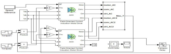 Figure 12. Simulink block diagram for multi-drives control.
We show the simulations for the next set of parameters.
Set of parameters no.1: Speed controller: Kp=30, Ki=20; Flux controller: Kp=100, Ki=3, hysteresis band of current controller=10A; speed estimator controller: Kp=500, Ki=5000; delay=10ms; the torque reference is given by the sequence: [0 0.5 1]sà [100 200 300]Nm; the torque distribution master-slave from load torque is balanced [0 0.5 1]sà [50 150 250]Nm.
Set of parameters no.2: Same control parameters like set no.1, delay=4ms; the torque reference is given by the sequence: [0 0.5 1 2]sà [100 200 300 400]Nm; the torque distribution master from load [0 0.5 1 2]sà [50 100 200 200]Nm; the torque distribution slave from load [0 0.5 1 2]sà [20 100 100 100]Nm.
Set of parameters no.3: Same control parameters like set no.1, delay=4ms; the torque reference is given by the sequence: [0 0.5 1 2]sà [100 200 300 400]Nm; the torque distribution master from load [0 0.5 1 2]sà [20 100 100 100]Nm; the torque distribution slave from load [0 0.5 1 2]sà [50 100 200 200]Nm.
In Figure 13 the overall drive performs well even for a delay of 10 ms, but with balanced distribution of torque load for the two engines. This simulation is equivalent of a linear movement for an excavator with tracks.
In Figure 14 for the sensorless type, in case of a left turn (master engine on the left) we shows that for an increased load torque in the master engine in relation to the slave engine, the equality of the electromagnetic torques is maintained between prescribed limits, but the slave engine speed is higher than the master engine speed. The behavior of the driving system for a turn to the right is similarly simulated (see Figure 15), so that for an increased load torque in the slave engine in relation to the master engine, the equality of the electromagnetic torques is maintained, but the slave engine speed is lower than the master engine speed.
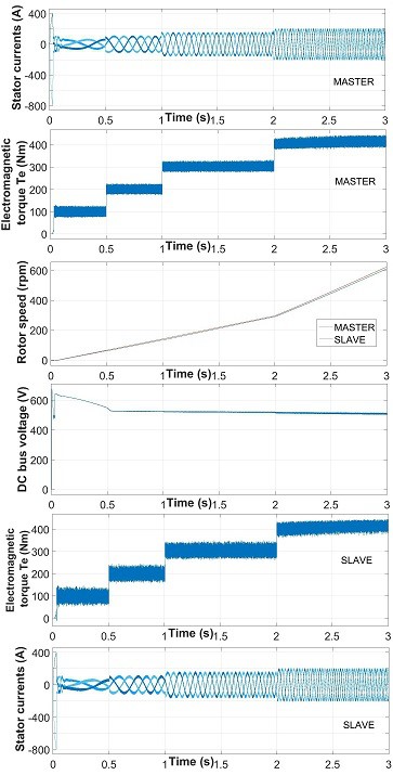 Figure 13. The simulation of master-slave drives model for the set no.1 of parameters of the controllers and references.
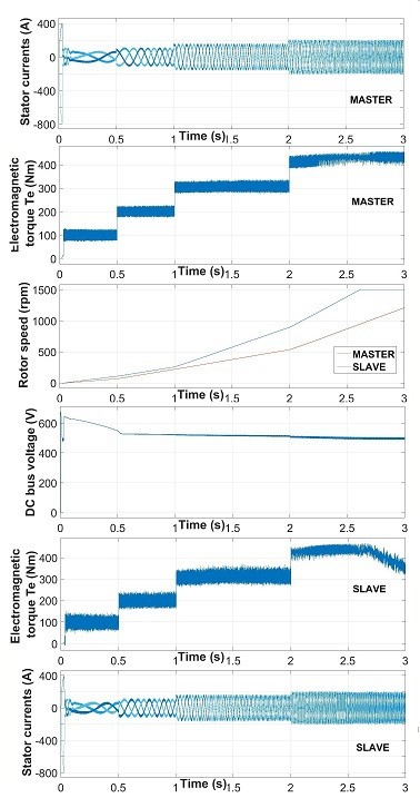 Figure 14. The simulation of master-slave drives model for the set no.2 of parameters of the controllers and references.
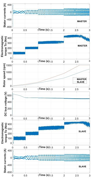 Figure 15. The simulation of master-slave drives model for the set no.3 of parameters of the controllers and references.
4. Hardware and Software Implementation
For hardware implementation of each Command and Control Unit we used the DSP dsPIC33EP810MU810 Microchip. This DSP have Harvard Architecture, 70 MIPS, Acc 40bits, PWM hardware blocks, USB, SPI and ECAN interfaces. For the three-phase diode rectifier block we used DD160N 160A / 2200V modules from Infineon and for three-phase inverter block we used LNC2W562M modules from Infineon. The current transducers are HAT 500-S from LEM with IPN = 500A, IPM= ±1500A and Ua = ±15V. The voltage transducers are LV 25-P-1000 from LEM with UPN = 10…500V and IPN = 10mA. The block diagram of hardware implementation for an application with one master and two slaves is presented in Figure 16 and contain the blocks: 1- c.c. circuit, 2-three-phase main inverter, 3- synchronization block, 4- PWM block, 5- induction motor, 6- output filter, 7- PWM block for recovery inverter, 8- three-phase recovery inverter, 9- estimation block, 10- voltage controller, 11- flux controller, 12- speed controller, 13- current controller, 14- data bus for CANopen protocol. The blocks 9 to 13 are implemented software in main DSP of each drive. An image of cabinet of hardware structure for multi-driving application is presented in Figure 17.
The software implementation is realized in MPLAB from Microchip. MPLAB is an integrated and development environment IDE, who contain editor, project manager, debugger, profiler and C/C++ optimizer. The software application supplies the following features: sensorless vectorially control of induction motors; automatically identification of electrical motor parameters; stability and fast response at fast changes of load; implementation of PWM Space Vector modulation; implementation of PI controllers and estimators; implementation of communication with PC host and local network communication with CANopen protocol. The main software blocks are: Init- make the configuration of registers and the limits of CAN converters; Clarke- implement the Clarke transformation; iClarke- implement the inverse Clarke transformation; Control- make the configuration of DSP; eCAN- make the configuration and activate the communication on CAN interface with other DSP; Ethet- make the configuration on Ethernet; Park- implement the Park transformation; iPark- implement the inverse Park transformation; Measure- implement the read and conversion of digital and analog ports; PI- make the configuration and implement the software PI controllers; Estim- implement the software estimators; SVgen- implement the software PWM Space Vector modulation; Timer- make the configuration of timers; Main- implement the main loop.
Following [19] all the software blocks that make the control of hardware structure are implemented on DSPs, for a functional application. The code for software blocks are implemented in MPLAB IDE, like a C language but optimized for DSP, where in a special format data Q15, the execution speed is increased even through the replacement of divide operations (large time consumer) by the shifting bit operations (low time consumer). When are make the implementation of the equation of speed Estimator in DSP, can appear some little errors due the data format representation instruction and the algorithm for increasing of accuracy of estimated speed value is presented in [19]. It’s worth to say that the software implementation in DSP is not a trivial task and represent the last stage and the validation of the chain: theory, design, simulation and implementation.
4.1. Rigid Coupling
Similar results with those of Section III are obtained even in the case of the functional application. In Figure 18 are presented the signals recorded on the PC host for 1 minute from multi-driving application 2×45 kW rigid coupling motors. The signals presented are: master and slave speed, DC bus voltage, master and slave output current and voltage filtered.
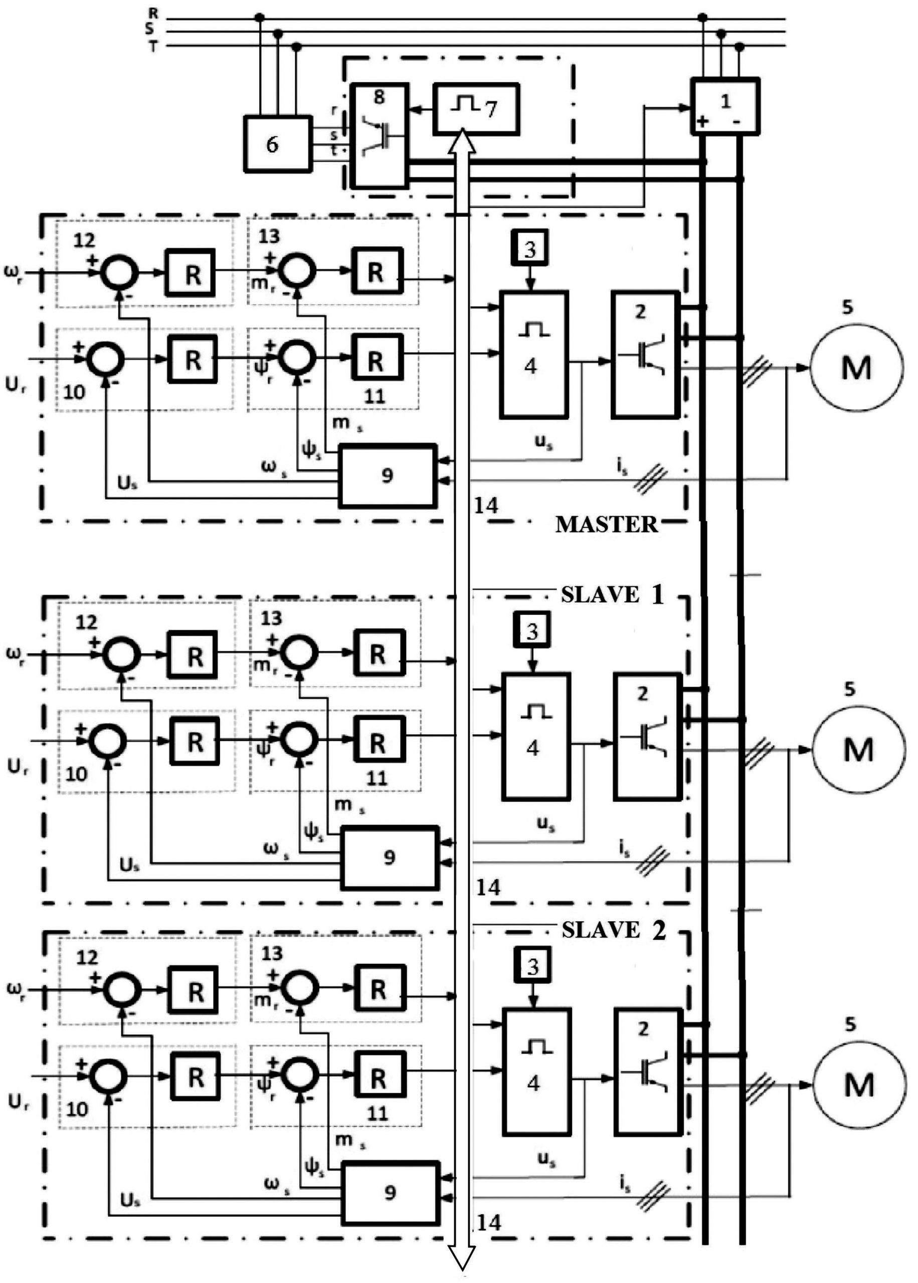 Figure 16. Hardware block diagram for electric multi-drives.
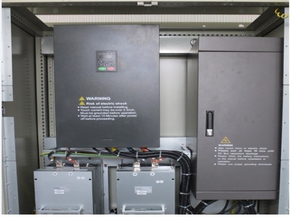 Figure 17. Picture of electric multi-drives equipment.
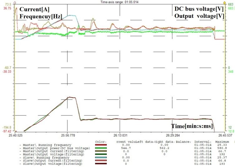 Figure 18. Signals recorded on the PC host from multi-driving application 2×45 kW rigid coupling motors.
The master and slave output speed (the red and blue line) are overlaid, indicating a very good control and stationary and dynamic performance even under acceleration and braking ramps. For each drives output voltage is directly proportional to engine speed and observe correct output voltage variation depending on engine speed. The current through motor is influenced by the functioning regime of drive motor (acceleration or braking) and by the variation of the shaft load (at constant speed). The variation of current is correct and correlated with the engine operating conditions. DC voltage value from intermediate circuit is the rectified and filtered voltage value of three-phase line voltage and is influenced by the functioning regime of drive motors (motor/generator) and the current through the motors.
4.2. Flexible Coupling
In Figure 19 are presented the signals recorded on the PC host for 7 minute from multi-driving application 3×75 kW flexible coupling motors. The signals presented are: master and slave’s output current and frequency. The relationship between torque (through current) and frequency can be seen in Figure 19.
Because of the inevitable mechanical wear and tear there are differences between the master and slaves motors (gearbox wear, ground composition, mud, movement in uphill and downhill). The system tries to compensate for these differences by controlling the mediated torque for each motor. There are oscillations caused by the track movement system. Because of wear and tear these track will have the following differences: different tension, different electro-mechanical braking time, different grip.
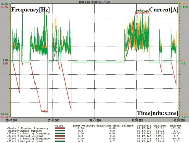 Figure 19. Signals recorded on the PC host from multi-driving application
3×75 kW flexible coupling motors.
Because of these differences when the system starts, the motors will develop completely different torque and the system is allowed to stabilize for 3 seconds, before activating the torque regulator. Only the protection features are active during the first 3 seconds, for protecting the VFDs, motors and gearboxes. In practice for the turning left or right, the upper limit frequency has been increased to 65Hz for 10 minutes so the motor from the outside trajectory can provide the necessary torque. In simulation it can be seen in Figure 14 and Figure 15 that in turn left and right the speed is maximum (1500rpm-50Hz) for motors from outside trajectory and the supplied torque is decreased.
There are a good control and stationary and dynamic performance even under acceleration and braking ramps and for front or back movement. For each drive the current through motor is influenced by the functioning regime of drive motor (acceleration or braking) and by the variation of the shaft load. The variation of currents is correct and correlated with the motors operating conditions.
5. Conclusions
It is obvious that the tuning of the controllers from the DSP will be slightly different from the one achieved through simulation, since simulations cannot identify every single mode and dynamic from practice, but the qualitative aspect will surely be maintained, and the good results achieved through simulations and the implementation of algorithms in the DSP which follow the direction of the ones in Simulink is a guarantee that the actual model will also function with good results. The system was tested in practice in surface mining, in acting of the large excavators, for a long time period with good results and proved this fact.
The results of the research consist in the implementation of the FOC sensorless control for an industrial multi-drive for applications with rigid or flexible coupling of motors, using same hardware but specifically software with rated output power between 45 kW and 75 kW.
In future approaches some interesting issues remain to be investigated, such as the digital implementation of more complex controllers for increasing the robustness and performance but optimized for DSP.
Acknowledgment
This work was carried out through the Partnerships in priority areas – PN II, developed with the support of MEN – UEFISCDI, project no. PN-II-PT-PCCA-2013-4-0157.
- M. Nicola, D. Sacerdotianu, and A. Hurezeanu, “Sensorless Control Using the Model Reference Adaptive Control Estimator in Electric Drives with High Dynamic” in International Conference on Applied and Theoretical Electricity, Craiova Romania, 2016. doi: [10.1109/ICATE.2016.7754642]
- C. Lascu, I. Boldea, and F. Blaabjerg, ‘‘Super-twisting sliding mode control of torque and flux in permanent magnet synchronous machine drives” in Proc. of IEEE Ind. Electron. Conf. (IECON 2013), Viena Austria, 2013. doi: [10.1109/IECON.2013.6699635]
- S.B. Veeranna, U.R. Yaragatti, and A.R. Beig, “Synchronized SVPWM algorithm for overmodulation region for three-level VSI” in Proc. of IEEE Ind. Electron. Conf. (IECON 2010), Glendale USA, 2010.
- V. Oleschuk, G. Grandi, “Algorithms, schemes and techniques of space-vector modulation for dual-inverter systems with symmetrical multilevel phase voltage” International Review on Modelling and Simulations (IREMOS), 5( 5), 1877-1866, 2012.
- V. Oleschuk, “PWM methods providing phase voltage symmetries in dual-inverter fed systems” Przeglad Electrotechniczny (Electrical Review), 89(6), 61-65, 2013.
- X. M. Chen, X. L. Gong, H. X. Zhou, Z. B. Xu, Y. G. Xu, and C. J. Kang, “An Economical Rapid Control Prototyping System Design with Matlab/Simulink and TMS320F2812 DSP” in Proc. of IMECS 2010, Hong-Kong, 2010.
- D. Bullo, A. Ferrara, and M. Rubagotti, “Sliding mode observers for sensorless control of current-fed induction motors” in American Control Conference, San Francisco USA, 2011.
- S. D. Genarro, J. R. Dominguez, and M. Meza, “Sensorless High Order Sliding Mode Control of Induction Motors with Core Loss” IEEE Transactions on Industrial Electronics, 61(6), 2678-2689, 2014. doi: [10.1109/TIE.2013.2276311]
- L. Wang, S. Chai, D. Yoo, L.Gan, K. and Ng, PID and predictive control of electrical drives and power converters using matlab/simulink, Wiley-IEEE Press, 2015.
- J. Rodriguez, P. Cortes, Predictive control of power converters and electrical drives, John Wiley & Sons, 2012.
- S. Ivanov, V. Ivanov, V. Rasvan, E. Bobasu, D. Popescu, and F. Stanga, “Predictive Versus Vector Control Of The Induction Motor” in 27th European Conference on Modelling and Simulation, Alesund Norway, 2013.
- B.K. Bose, Modern Power Electronics and AC Drives, New Jersey: Prentice Hall, 2002.
- G. Sieklucki, “Analysis of the transfer-function models of electric drives with controlled voltage source” Przeglad Elektrot., 7, 250-255, 2012.
- C. Lascu, S. Jafarzadeh, M. S. Fadali, and F. Blaabjerg, “Direct Torque Control With Feedback Linearization for Induction Motor Drives” IEEE Transactions on Power Electronics, 32(3), 2072-2080, 2017. doi: [10.1109/TPEL.2016.2564943]
- S. Legrioui, S. E. Rezgui, and H. Benalla, “Robust IM exponential reaching law sensorless control with MRAS-based online parameters identification” in IEEE 15th International Conference on Environment and Electrical Engineering, Rome Italy, 2015. doi: [10.1109/EEEIC.2015.7165265]
- C. Fahassa, Y. Zahraoui, M. Akherraz, and A. Bennassar, “Improvement of induction motor performance at low speeds using fuzzy logic adaptation mechanism based sensorless direct field oriented control and fuzzy logic controllers” in 5th International Conference on Multimedia Computing and Systems, Marrakech Morocco, 2016. doi: [10.1109/ICMCS.2016.7905545]
- G. Pavithra, G. R. P. Lakshmi, “Simulation of neuro fuzzy and ANFIS in sensorless control of BLDCM drive for high speed application” in 2015 International Conference on Computation of Power, Energy, Information and Communication, Madras India, 2015.
- SimPowerSystem[Online].Available:http://www.mathworks.com/products/simpower/model-examples.html.
- Microchip dsPIC33EP256MU810 datasheet [Online]. Available: http://www.microchip.com/wwwproducts/en/dsPIC33EP256MU810
- CANopen–The standardized embedded network [Online]. Available: https://www.can-cia.org/canopen/
- M. Nicola, D. Sacerdotianu, and A. Hurezeanu, “Simulation and Implementation of Sensorless Control Using Estimators in Electric Drives with High Dynamic” Annals of the University of Craiova, Electrical Engineering Series, 40, 86-93, 2016.