Channel Inversion Schemes with Compensation Network for Two-Element Compact Array in Multi-User MIMO
Volume 2, Issue 4, Page No 26-31, 2017
Author’s Name: Maxwell Oppong Afriyiea), Obour Agyekum Kwame Opuni-Boachie, Affum Emmanuel Ampoma
View Affiliations
University of Electronic Science and Technology of China, Communication and Information Engineering, 611731, China
a)Author to whom correspondence should be addressed. E-mail: mmaxi12002@yahoo.com
Adv. Sci. Technol. Eng. Syst. J. 2(4), 26-31 (2017); ![]() DOI: 10.25046/aj020404
DOI: 10.25046/aj020404
Keywords: Broadcasting channel, Channel Inversion, Coupling matrix, Inserted component scheme, MIMO, Multi-user, Receiving mutual impedance

Export Citations
In this paper, we investigate the performance of channel inversion schemes for interference cancellation with compensation network in multi-user MIMO broadcasting channel. To achieve good performance, mutual coupling between two-element compact arrays is characterized by the receiving mutual impedance method (RMIM) to formulate the compensation network-operating matrix. A prototype of two-element compensation network with an insertion loss between input and output ports better than 11 dB is fabricated. We demonstrate results to confirm that output voltages of decoupling network can effectively be removed off the coupling effect. A typical standard MIMO channel model is presented, and system performance is evaluated when coupling effects existed and after decoupling process. Bit error performance results also indicate the promising potentials of regularized channel inversion scheme with efficient decoupling scheme in massive MIMO system.
Received: 01 March 2017, Accepted: 04 April 2017, Published Online: 15 April 2017
1. Introduction
The expanding interest for higher data rate, greater spectrum efficiency, larger average throughput and shorter latency by wireless systems has stimulated tremendous amount of research towards capacity enhancements of the communication links [1]. The main challenge in data transmission in broadcasting channel is interference cancellation, and channel inversion is one of the advanced technologies developed to confront the challenge. Channel Inversion (sometimes referred to as “zero-forcing (ZF) beamforming”) can be viewed as a precoding strategy to undo the effects of a channel, and is one of the simplest modulation techniques for the multiuser channel [2]. This technique multiplies the vector signal to be transmitted by the inverse of the channel matrix and the result is an equalized channel to each user, and therefore, suppresses the co-channel interference [3]. It has the following advantages in the MIMO context: it is implementable with a non-iterative transmitter processing and unitary receiver processing [2], [4], and [5], therefore, no noise improvement happens at the receiver. Again, when the channel rank is restricted by the number of receiver antennas, receiver processing is not required, and the subsequent virtual channels correspond one-to-one with the receiver antennas.
Channel inversion has attracted tremendous amount of research, and is well investigated in light of the fact that it is suitable for multi-user MIMO downlink channels [6]-[11]. One noteworthy issue that should be tended to in connection to multi-user MIMO system is mutual coupling, and the development of a successful decoupling strategy to compensate the performance degradation in MIMO antennas. If mutual coupling is strong, a large portion of the power fed into one port will be coupled to the other port rather than radiating to free space; consequently diminishing the signal-to-noise ratio and restricting the channel capacity. Ref. [12] separates decoupling strategies into four classes: 1) Eigen-mode Decomposition Scheme: Its guideline is to diagonalize the scattering matrix of a compact array using and /or [13]-[17]. 2) The Inserted Component Scheme: It works on the concept of inserting a section of transmission-line between the coupled antenna ports [18]-[22]. 3) Artificial Structure Decoupling Scheme: This method uses sub-wavelength EM structures such as electromagnetic band gap (EBG) structure [23], defected ground structures (DGS) [24], and magnetic metamaterials [25], [26]. 4) Coupled Resonator Decoupling Scheme: This method was proposed for the first time in 2014, and has the concept of decoupling pair of coupled elements using coupled resonators [12] and [27]-[30].
It is clear at this point that decoupling techniques to balance the performance degradation by coupling are widely investigated. However, its coexistence with channel inversion needs further investigation, importantly, the effects of coupling matrix on the channel coefficients, and the resulting consequences on channel inversion interference cancellation schemes that are rarely accounted for or are studied in the signal processing or communication literature. We intend to investigate the system performance of channel inversion with decoupling network scheme in multi-user MIMO system by evaluating error performance of the coupled and decoupled antenna elements at the receiving end. This paper systematically presents the measurement of receiving mutual impedance of monopole array to formulate the decoupling network operating matrix and design. For illustration, coupling matrix under coupled and compensated voltages is determined and included in the multi-user MIMO system with channel inversion interference cancellation model for the broadcasting channel.
The purpose of decoupling network however is to enhance the isolation between ports closely located within restricted space in mobile handset. It is therefore reasonable to investigate the effect of mutual coupling matrix on channel coefficients, and subsequent effects on performance of channel inversion in MIMO system after decoupling process. For reasons of clarity, the contribution of this paper is to demonstrate the impacts of mutual coupling on channel inversion after the decoupling process. We do this by fabricating a two-element decoupling network to explore the effect of coupling matrix when incorporated in the MIMO system model with channel inversion algorithm. BER performance results also indicate the promising potentials of regularized channel inversion scheme with efficient decoupling scheme in massive MIMO system
The outline of the paper is as follows: Section II presents channel inversion, coupling matrix, system and channel model. The theory of receiving mutual impedance to formulate coupling effect and to design the inserted component scheme are described in Section III. Section IV presents simulation results and discussions. Finally, we give concluding remarks in Section V.
2. System and Channel Model
In this paper, a standard MIMO channel of transmitters and receivers represented as a matrix of dimension is presented, where each of the entries is a zero-mean unit-variance complex-Gaussian fading gain. The received signal of each user can be represented as [31]
![]() where is the signal sent from the antenna, and defined as a standard complex-Gaussian receiver noise seen at the user. In a vector form, the receive signal is represented as
where is the signal sent from the antenna, and defined as a standard complex-Gaussian receiver noise seen at the user. In a vector form, the receive signal is represented as
where and . The scaling factor is introduced to restrict the transmit power to some predetermined value
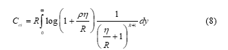
![]() We assume that the total transmit signal power . The ergodic sum capacity of users with single receive antenna system in (bits/channel use) is expressed as [12], [13]
We assume that the total transmit signal power . The ergodic sum capacity of users with single receive antenna system in (bits/channel use) is expressed as [12], [13]
![]() where is the set of all nonnegative diagonal matrices with , is the Hermitian transpose of . We just consider impacts of mutual coupling and channel correlation of two-element compact array closely placed to each other due to the relatively limited space at the receiver. Hence, the channel is given by [32]
where is the set of all nonnegative diagonal matrices with , is the Hermitian transpose of . We just consider impacts of mutual coupling and channel correlation of two-element compact array closely placed to each other due to the relatively limited space at the receiver. Hence, the channel is given by [32]
![]() and denote the coupling matrix and spatial correlation matrix at the receiver respectively. The coupling matrix of the antenna array can be written as [33]
and denote the coupling matrix and spatial correlation matrix at the receiver respectively. The coupling matrix of the antenna array can be written as [33]
![]() where is the antenna impedance in isolation, is identity matrix, is the impedance of the receiver at each antenna element, chosen as the complex conjugate of and is the mutual impedance.
where is the antenna impedance in isolation, is identity matrix, is the impedance of the receiver at each antenna element, chosen as the complex conjugate of and is the mutual impedance.
A. Plain and Regularized Channel Inversion Schemes
Recently, channel inversion has been introduced as one of transmission schemes for interference cancellation in multi-user multi input multi-output (MIMO) broadcasting channels. In the plain channel inversion (CI), data symbol is precoded with the pseudo-inverse of the channel prior to transmission; the precoded data symbol is calculated as
![]()
As indicated by [31], the main drawback of this approach is the high power level required to cancel the small elements of and this arises when the channel is ill conditioned. The plain channel inversion capacity is expressed as [7]-[31]
 where , as , bits per channel use. The regularized channel inversion (CI-R) approach is equivalent to using a minimum mean-squared error (MMSE) criterion to design the beamformer weights. This method reduces the effects of noise amplification by regularizing the inverse in the ZF filter. The precoded data symbol solution at the transmitted side is
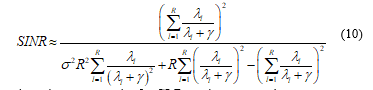
![]() where is the regularization parameter. Let the signal-to-interference noise ratio (SINR) be represented by [7] (10) then, the sum capacity for CI-R can be expressed as
where is the regularization parameter. Let the signal-to-interference noise ratio (SINR) be represented by [7] (10) then, the sum capacity for CI-R can be expressed as
 3. Theory and Design of the Inserted Component Scheme
A. Formulation for the Mutual Coupling Effect
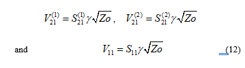
Mutual coupling effect between two receiving monopoles for the study is characterized by receiving mutual impedance method (RMIM) described in [34]. The two parallel monopoles operating at 2.4 GHz are placed on a metallic ground plane and connected to a load in anechoic chamber. The monopoles have length of 30 mm, radius of 2 mm and element separation of 25mm (0.2 at 2.4 GHz). The transmitting antenna is a horn antenna, whereas a separation of 50 mm is given between transmitting antenna and receiving monopole array. Considering the concealed impacts of the metallic ground, the scattering parameters , and are measured utilizing the procedure in [34]. If is complex and represents the square root of the transmitted power, the respective terminal voltages can be calculated as [35]
 The voltage and current relationships can be expressed as
 and
and
 After some manipulations, the mutual coupling between array elements is expressed as
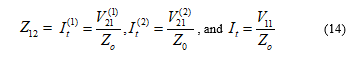
 Consider a receiving antenna with array of elements, the relationship between the uncoupled voltages and the received coupled voltages can be written in a matrix notation as [36]
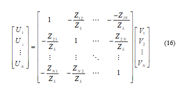 where represents the mutual impedance between the and the antenna elements and is the terminal impedance connected to the antennas.
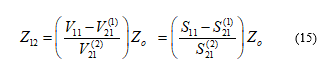
B. Operating Matrix and Design of Compensation Network
Using (16), the operating matrix for two-element receiving array for the compensation network is expressed as
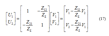 where and are the couple voltages and the inputs to the network from the monopole terminals and the output voltages are and , also known as the compensation voltages. The compensation network is designed using a power-divider of unequal power-dividing ratio with no active circuit elements to minimize extra circuit noise and two rat-race couplers [37]. The power divider has three transmission lines ( , and ), each having impedance of , where is the system’s characteristic impedance, but unequal electrical lengths. The electrical length can be defined as , whereas and are and respectively.
The even-mode circuit for the power divider is shown in Fig. 1, where and are the input admittances of the upper and lower branches respectively. In the odd-mode shown in Fig. 2, if is the power ratio, then and are the magnitude of voltage sources at the output ports of the divider circuit. We fabricate the circuit by using the substrate FR4 with dielectric constant 4.8 at operating frequency of 2.4 GHz as shown in Fig. 3. The measured insertion losses between input and output ports of the decoupling network are shown in Fig. 4.
4. Simulation Results and Discussion
For demonstrating the performance of channel inversion schemes with decoupling network in multi-user MIMO system effectively, coupling matrix of the decoupling network under two distinct conditions is determined in an anechoic chamber. In this work, the decoupling network has been fabricated using microstrip transmission-lines, the measured insertion loss between input and output ports are better than 11 dB. The scattering parameters of the coupled monopole array are measured to determine the coupled voltages ( and ) and coupling matrix.
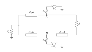 Fig. 1. Odd-mode circuit of proposed power divider.
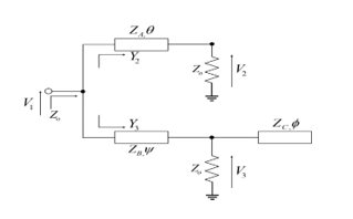 Fig. 2. Even-mode circuit of proposed power divider.
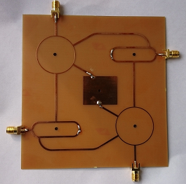 Fig.3. Photograph of the fabricated inserted compensation network.
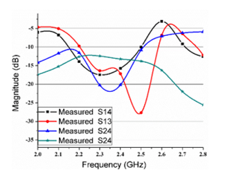 Fig.4. Measured insertion loss between input ports 1&2 and output ports 3&4
The monopole antennas in the array are connected to the decoupling network through equivalent length coaxial links and scattering parameters of the output ports of the decoupling network are measured to determine the coupling matrix for the compensated voltages ( and ). These are incorporated into the channel inversion schemes of the multi-user MIMO broadcasting channel for performance evaluation. The BER performance of a multi-user MIMO system for plain and regularized channel inversion schemes are shown in the Fig. 5 and Fig. 6 respectively. It is clear that performance of the coupled voltages at different frequencies must incur losses to make practically identical results for the compensated voltages for the same bit error performance in both schemes due to the coupling phenomenon.
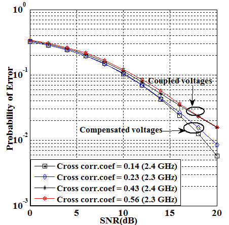 Fig.5. Bit error performance of plain channel inversion with decoupling network
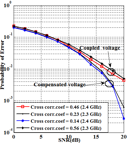 Fig.6. Bit error performance of regularized channel inversion with decoupling network
The simulation results also supports the variations of cross correlation coefficients recorded by the procedure in [38] under both conditions. As it can be seen, the regularized scheme accomplishes better performance than plain scheme, thanks to mitigating noise enhancement. Again, in Table I, the last row defines the ratio of the voltage obtained with monopole B to the voltage obtained with monopole A. Results confirm that the ratio of the compensated voltage is very close to the uncoupled voltages, demonstrating that the compensated voltages have successfully been removed off the coupling effect. It is a known fact that channel inversion provides effective interference cancellation in multi-user broadcasting channel, however, our analysis demonstrates that an efficient decoupling network with channel inversion schemes enhance system performance and demonstrated the lesser impacts of coupling on the compensated voltages in multi-user MIMO. This is because coupling matrix can have decorrelation effect on the channel coefficient and therefore improving the error performance of multi-user MIMO system.
5. Conclusion
In this paper, we demonstrate the effect of coupling matrix on channel coefficient, and the resulting consequences on channel inversion interference cancellation schemes in multi-user MIMO system. Our results confirm that the output of the decoupling network can adequately be removed off the coupling effect. In the event that coupling affects the performance of antenna arrays, our outcomes demonstrate an opposite case. This is because the lesser impacts of coupling on the compensated voltages also translated into an improved bit error performance, indicating the promising potentials of regularized channel inversion scheme with efficient decoupling scheme in multi-user MIMO system.
TABLE I
MEASURED RECEIVING VOLTAGES
| Uncoupled Voltages (reference) | Coupled voltages | Compensated voltages | ||
| Monopole A | mag (mV) | 16.64 | 12.4 | 11.55 |
| angle ( ) | -160.64 | -166.67 | 34.967 | |
| Monopole B | mag (mV) | 16.54 | 15.42 | 12.30 |
| angle ( ) | -139.56 | -141.46 | 55.16 | |
| B/A | mag | 0.9939 | 1.2199 | 1.065 |
| angle ( ) | 21.08 | 25.208 | 20.193 | |
Acknowledgment
The authors are grateful to all the members of Center for RFIC and System Technology, School of Communication and Information Engineering, University of Electronic Science and Technology of China for relevant advice and discussion to this work.
- G. Caire and S. Shamai, “On the achievable throughput of a multiantenna Gaussian broadcast channel,” IEEE Trans. Inform. Theory, vol. 43, pp. 1691-1706, July 2003.
- T. Haustein, C. von Helmolt, E. Jorswieck, V. Jungnickel, and V. Pohl, “Performance of MIMO systems with channel inversion,” in Proc. IEEE Vehicular Technology Conference, VTC Spring, Birmingham, AL, pp. 35–39, May 2002.
- C. B. Peel, B. Hochwald, and A. L. Swindlehurst, “A Vector- Perturbation Technique for Near-Capacity Multiantenna Multiuser Communication-Part I: Channel Inversion and Regularization,” IEEE Transactions on Communications, vol. 53, pp. 195–202, January 2005.
- E. Jorswieck, G. Wunder, V. Jungnickel, and T. Haustein, “Inverse eigenvalue statistics for Rayleigh and Rician MIMO channels,” in MIMO: IEE Seminar on Communications Systems from Concept to Implementations, pp. 1–3, Dec. 2001.
- V. Jungnickel, T. Haustein, E. Jorswieck, and C. von Helmolt, “A MIMO WLAN based on linear channel inversion,” IEE Seminar on in MIMO: Communications Systems from Concept to Implementations, pp. 1–20, Dec. 2001.
- H. Lee, K. Lee, B. M. Hochwald, and I. Lee, “Regularized channel inversion for multiple-antenna users in multiuser MIMO downlink,” in Proc. International Conference on Communications, Beijing, China, pp. 3501–3505, May 2008.
- V. Jungnickel, T. Haustein, V. Pohl, and C. von Helmolt, “Link adaptation in a multi-antenna system,” in Proc. Vehicular Technology Conference, VTC Spring, vol. 2, pp. 862–866, Jeju, Korea, Apr. 2003.
- C. Masouros and E. Alsusa, “Dynamic linear precoding for the exploitation of known interference in MIMO broadcast systems,” IEEE Trans. Wireless Commun., vol. 8, no. 3, pp. 1396–1404, Mar. 2009.
- P. Viswanath and D. Tse, “Sum capacity of the vector Gaussian broadcast channel and uplink downlink duality,” IEEE Trans. Inf. Theory, vol. 49, pp. 1912–1921, Aug. 2003.
- S. Vishwanath, N. Jindal, and A. Goldsmith, “Duality, achievable rates, and sum capacity of Gaussian MIMO broadcast channels”, IEEE Trans. Inf. Theory, vol. 49, pp. 2658–2668, Aug. 2003.
- L. Zhao, L. K. Yeung, and K.-L. Wu, “A coupled resonator decoupling network for two-element compact antenna arrays in mobile terminals, ”IEEE Trans. Antennas Propag., vol. 62, no. 5, pp. 2767–2776, May 2014.
- J. C. Coetzee and Y. Yu, “Port decoupling for small arrays by means of an eigenmode feed network,” IEEE Trans. Antennas Propag., vol. 6, pp. 1587–1593, Jun. 2008.
- S. Zuo, Y.-Z. Yin, Y. Zhang, W.-J.Wu, and J.-J. Xie, “Eigenmode decoupling for MIMO loop-antenna based on 180 coupler,” Progr. Electromagn. Res. Lett., vol. 26, pp. 11–20, 2011.
- S. K. Chaudhury, H. J. Chaloupka, and A. Ziroff, “Multiport antenna Systems for MIMO and Diversity,” presented at the EUCAP, Barcelona, Spain, Apr. 2010.
- C. Volmer, J. Weber, R. Stephan, K. Blau, and M. A. Hein, “An eigen analysis of compact antenna arrays and its application to port decoupling,” IEEE Trans. Antennas Propag., vol. 56, no. 2, pp. 360–370, Feb. 2008.
- L. K. Yeung and Y. E. Wang, “Mode-based beamforming arrays for miniaturized platforms,” IEEE Trans. Microw. Theory Tech., vol. 57, no. 1, pp. 45–52, Jan. 2009.
- J. B. Andersen and H. H. Rasmussen, “Decoupling and descattering networks for antennas,” IEEE Trans. Antennas Propag., vol. 24, no. 6, pp. 841–846, Nov. 1976.
- S. Chang, Y.-S. Wang, and S.-J. Chung, “A decoupling technique for increasing the port isolation between strongly coupled antennas,” IEEE Trans. Antennas Propag., vol. 56, no. 12, pp. 3650–3658, Dec. 2008.
- C.-Y. Lui, Y.-S. Wang, and S.-J. Chung, “Two nearby dual-band antennas with high port isolation,” presented at the IEEE Int. Symp. Antennas Propag., San Diego, CA, USA, Jul. 2008.
- A. Diallo, C. Luxey, P. L. Thuc, R. Staraj, and G. Kossiavas, “Study and reduction of the mutual coupling between two mobile phone PIFAs operating in the DCS1800 and UMTS bands,” IEEE Trans. Antennas Propag., vol. 54, no. 11, pp. 3063–3073, Nov. 2006.
- C. Luxey, “Design of multi-antenna systems for UTMS mobile phones,” in Proc. Loughborough Antennas Propag. Conf., pp. 57–64. Nov. 2009.
- F. Yang and Y. R. Samii, “Microstrip antennas integrated with electromagnetic band-gap EBG structures: A low mutual coupling design for array applications,” IEEE Trans. Antennas Propag., vol. 51, no. 10, pp. 2936–2946, Oct. 2003.
- C. Y. Chiu, C. H. Cheng, R. D. Murch, and C. R. Rowell, “Reduction of mutual coupling between closely-packed antenna element,” IEEE Trans. Antennas Propag., vol. 55, no. 6, pp. 1732–1738, Jun. 2007.
- M. M. Bait-Suwailam, M. S. Boybay, and O. M. Ramahi, “Electromagnetic coupling reduction in high-profile monopole antennas using single-negative magnetic metamaterials for MIMO applications,” IEEE Trans. Antennas Propag., vol. 58, no. 9, pp. 2894–2902, Sep. 2010.
- B. K. Lau and J. B. Andersen, “Simple and efficient decoupling of compact arrays with parasitic scatterers,” IEEE Trans. Antennas Propag., vol. 60, no. 2, pp. 464–472, Feb. 2012.
- L. Zhao, L. K. Yeung, and K.-L. Wu, “A coupled resonator decoupling network for two-element compact antenna arrays in mobile terminals,” IEEE Trans. Antennas Propag., vol. 62, no. 5, pp. 2767–2776, May 2014.
- L. Zhao and K.-L. Wu, “A broadband coupled resonator decoupling network for a three-element compact array,” in Proc. IEEE MTT-S Int. Microw. Symp. pp. 1–3. Jun. 2013.
- L. Zhao, L. K. Yeung, and K. L. Wu, “A novel second-order decoupling network for two-element compact antenna arrays,”Proc. Asia-Pacific Microwave Conf., 2012.
- K. Qian, L. Zhao, and Ke-Li Wu, “An LTCC Coupled Resonator Decoupling Network for Two Antennas” IEEE Transactions on Antennas and Propagation, vol. 63, No. 7, July 2015.
- Lin Yang, Emad Alsusa, Ulises Pineda Rico and Enrique Stevens Navarro “Linear Selective Channel Inversion Technique for Multi-user MIMO systems” IEEE 72nd Vehicular Technology Conference Fall (VTC 2010-Fall), pp. 1 – 5, 6-9 Sept., 2010
- Appaiah, K.; Ashikhmin, A; Marzetta, T.L “Pilot contamination reduction in multi-user TDD systems.” in Proc. IEEE International Conference on Commu. (ICC), pp. 1-5, 2010.
- T. Svantesson and A. Ranheim, “Mutual coupling effects on the capacity of multi-element antenna systems,” in Proc. IEEE In Conf.: Acoustics,Speech, and Signal Processing, vol. 4, pp. 2485-2488, Salt Lake City, UT, May 7-11, 2001.
- H. T. Hui, “A new definition of mutual impedance for application in dipole receiving antenna arrays,” IEEE Antennas Wireless Propagat. Lett, vol. 3, pp. 364–367, 2004.
- D. M. Pozar, Microwave Engineering. Reading, MA: Addison-Wesley, 1990.
- Y. Yu and H.T. Hui “Design of a Mutual Coupling Compensation Network for a Small Receiving Monopole Array” IEEE Trans. On Micro. Theory and Techniques, vol. 59, no. 9, September 2011.
- K. K. Cheng and P. W. Li, “A novel power-divider design with unequal power-dividing ration and simple layout,” IEEE Trans. Microw. Theory Tech., vol. 57, no. 6, pp. 1589–1594, Jun. 2009.
- K. Jeongpyo and C. Jaehoon, “Dual band MIMO antenna using ENG zeroth order resonator for 4G system,” IEEE International Worskhop on, Antenna Technology, 2009. (IWAT), pp. 1-4, 2009.
Citations by Dimensions
Citations by PlumX
Google Scholar
Scopus
Crossref Citations
No. of Downloads Per Month
No. of Downloads Per Country