Adapting Model Predictive Control for a PV Station and Evaluating two different MPPT Algorithms P&O and FLC
Adapting Model Predictive Control for a PV Station and Evaluating two different MPPT Algorithms P&O and FLC
Volume 2, Issue 3, Page No 741-748, 2017
Author’s Name: Imad Elzein1, a), Yury Petrenko2
View Affiliations
1Dep. of Electrical Engineering and Control systems, Belarusian National Technical University, Minsk, Belarus
2Dep. of Electrical Engineering and Control systems, Belarusian National Technical University, Minsk, Belarus
a)Author to whom correspondence should be addressed. E-mail: imad.zein@liu.edu.lb
Adv. Sci. Technol. Eng. Syst. J. 2(3), 741-748 (2017); ![]() DOI: 10.25046/aj020394
DOI: 10.25046/aj020394
Keywords: Fuzzy logic controller, MPPT, Photovoltaic

Export Citations
In this paper first discussion approach will stress out the integration of model predictive control in maximum power point tracking MPPT and as progressing a second approach identified as fuzzy logic controller FLC and perturb & Observe P&O algorithms are analyzed. All are interrelated to MPPT model for a photovoltaic module, PVM, to search for and generate the maximum power; in this case what’s called Pmax. As per the first technique the focus is on the optimal duty ratio, D, for a series of multi diverse types of converters and load matching. The design of the MPPT for a stand-alone photovoltaic power generation system is applied where the system will consist of a solar array with nonlinear time varying characteristics, and a converter with appropriate filters. The integration of model predictive control will be addressed first in this paper. The second fold will implement an MPPT system that use the FLC and compare it with a P&O) algorithm through the utilization of Simulink.
Received: 20 March 2017, Accepted: 03 June 2017, Published Online: 16 June 2017
1. Introduction
It has been obvious that maximum power point tracking algorithm is currently playing a vital role to enhance the efficiency of the solar panel as less than 40% of energy incident is being converted into electrical energy. Due to the growing dependency and the increasing need in acquiring electricity, and due to the limitations in supply and the uprising prices of conventional sources (such as the continuous increase in electrical bills, generation, distribution, and maintenance of the electrical plants, fluctuating petroleum prices, etc.), photovoltaic (PV) energy vitality turns into a promising option as it is inescapable, openly accessible, environmentally promising, and has less operational and upkeep costs. Along these lines, the interest of PV era systems is by all accounts expanded for both standalone and grid-connected modes of PV systems. As a result, an efficient maximum power point tracking (MPPT) technique is vital for tracking the MPP at all environmental conditions and then push forward the PV system to functionally be operable at that MPP point. Undesirably, photovoltaic generation systems have two note-worthy issues: the conversion efficiency in electric power generation is somehow low (normally below 17 percent particularly under low irradiation conditions), and the amount of electric power generated by solar arrays changes persistently with climate conditions. Numerous MPPT methodologies have been recommended in the literature; the Perturb and Observe (P&O), the Incremental Conductance (IC), the Artificial Neural Network, and the Fuzzy Logic methods, etc. It has been noticed that the efficiency of the PV is influenced by the following two parameters: the panel’s irradiance and temperature which are stochastic and unpredictable. In any PV module a DC/DC converter is accountable for transferring maximum power to the load.
Unfortunately and since the MPP point must be sought, this can be achieved in either computation models or search algorithms. Figure 1 illustrates an MPPT module diagram.
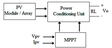
Figure1.MPPT module diagram
We have to stress out that the voltage across the power conditioning unit (DC-DC converter) is fed to get an isolated load. The input-output (I/P-O/P) voltage relationship for converter conduction mode is given by duty cycle. As a result, the forthcoming of this paper is an extension of a previous research outcome that was originally presented in the International Conference on Smart Systems and Technologies (SST 2016) to recompense for the parametric variations that took place due to the effect of temperature and irradiance variations, where a controller was utilized to be adaptive to environmental changes. The extension of the already published paper will be expanded towards proposing an innovative fuzzy logic controller (FLC) for DC–DC converters that yield to an effective element of MPPT system so that it integrate itself into enhancing the photovoltaic modules to work under changeable operating conditions as well as dealing with the nonlinear properties of DC-DC power converters [1].
2. Overview of model predictive control
MPC is a model in view of line control approach with the following accompanying modules: a prediction horizon, a receding horizon procedure, and a regular update of the model and re-computation of the optimal control input [2,3,4,5]. A block diagram of MPC system is shown in Figure. 2. A process model is used to predict the current values of the output variables. The residuals, the differences between the actual and predicted outputs, serve as the feedback signal to a Prediction block. The predictions are utilized as a part of two types of MPC calculations that are performed at each sampling instant: the first is the set-point calculations and the second is the control calculations.
The set points for the control calculations, which are called targets, calculated from an economic optimization based on a steady-state model of the process, conventionally, a linear model. In MPC the set points are customarily computed each time the control calculations are conducted.
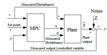
Figure 2.Block diagram for MPC
3. Nonlinear predictive control
The basic principle of model predictive control is shown in Figure 3. At a denoted time (t) certain measurements are provided, which will trigger the controller to predicts the future dynamic behavior of the system over a prediction horizon Tp and furthermore determine (over a control horizon Tc≤ Tp) the input under the condition a predefined open-loop performance objective is optimized.
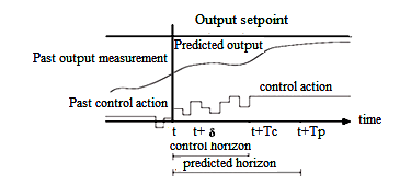
Figure 3.Principle of model predictive control
When neither disturbances exist nor mismatching model plant presence is evident, and if the optimization problem could be solved for infinite horizons, then we can apply the input function found at time t=0 to the system for all times t ≥ 0.As a matter of fact, this is not feasible generally. Because of the factors of disturbances and the stressing model-plant mismatch, the real system behavior is going to differ from the predicted behavior. To integrate a feedback scheme, the open-loop manipulated input function acquired will be ready for implementation as the next measurement becomes available. The time difference between the recalculation/measurements can vary, however often it is assumed to be fixed, i.e. the measurement will take place every δ sampling time-unit. Using the new measurement at time (t + δ), then the whole process for the prediction and optimization is going to be repeated to find a new input function with the control and prediction horizons moving forward. Knowing that in Figure 3 the input is depicted as arbitrary function of time. For numerical solutions of the open-loop optimal control problem it is often necessary to parameterize the input in an appropriate way. This is normally achieved by employing a finite number of basic functions; as an example the input could be approximated as piecewise constant over the sampling time δ. The computation of the applied input (based on the predicted system behavior) permits the inclusion of constraints on states and inputs as well as the optimization of a given cost function. In general the predicted system behavior will differ from the closed-loop one; and thus further cautionary should be taken into account to achieve closed-loop stability.
We consider the stabilization problem for a class of systems described by the following nonlinear set of differential equations: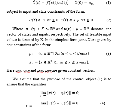
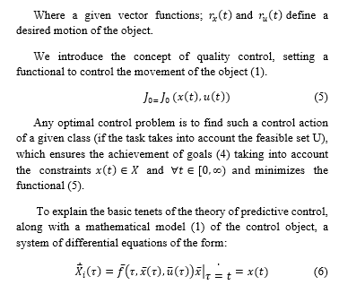
Is considered, where – the state vector, – the vector control, We assume that the function has the same properties as the function and vectors, and taking the value of the admissible sets, and respectively.
In addition, let us assume that the function is set in such a way that for any admissible control vector functions and , satisfy the system (1) and (6) respectively; and are close to each other at a rate for each .
The system of differential equations (6) is called predictive model in relation to the mathematical model (1) of the control object.
A practical view of photovoltaic energy conversion station is presented in Figure 4, where the source of energy, represented by the solar array PHVS with filter C delivers power to DC-DС power converter, such as buck, boost or buck-boost converters; which depends on specific architecture of the entire system to select one of the above-mentioned types. For instance, if PHVS is considered to supply power to a DС distribution network (i.e. a space station power network) than power interface will provide conditioned DС power. In case the main utilization was for smart-home application with AC power distribution network then independently controlled DС-АС inverter with built in PWM control may be used. The interface links between PHVS and the consumer grid may include other elements such as energy-storage devices (i.e. batteries or super capacitors), which require specific controllers to run “charge-discharge” mode of operation. We have to bear in mind that control designs for interfaces devices are ignored.
The objective of DС-DС converter on PHV station MPPT system is to regulate the output voltage (Figure 4) under wide range of operations and PHV nonlinearity characteristics, caused by existing atmospheric conditions and load variation. The controller task is to deliver output signal D (Figure 4) to follow MPPT [6] and constraints of the circuit.
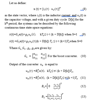
DС-DС boost converter schematic is in a view of lumped parameter circuits used for control design and represented in Figure 5.
The coil non-linearity’s is neglected, and the switch is also considered ideal. At each switching instant, the stray inductor and parasitic capacitor are also neglected. After this assumptions the lumped parameter switched model represent the linear inductance value associated to the coil L, which losses are accounted for represent capacitance and equivalent series resistor of C.
Output load presented by resistor The switching stages of the converter are formalized through the switch S, representing the dual operated semiconductor component [7]. The converter operation characterizes by switching period (corresponding frequency ).
The DС component of the output voltage regulated through the duty cycle D[k], (Figure. 4), which is defined by:![]()
Where ] represents the time interval during the kth switching period; during which S is in the position 1 for the boost converter, connecting to the supply
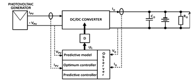
Figure 4.Photovoltaic station model predictive control block diagram
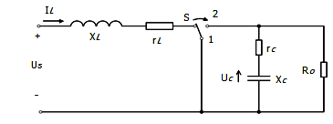
Figure 5 Lumped parameter model of the boost converter
4. Fuzzy logic controller approach for photovoltaic Station
A standout amongst the most noteworthy problems in PV module and MPPT effectiveness is DC-DC converter. As of late, there has been expanding eagerness for the advancement of proficient control procedures to enhance dynamic conduct of DC–DC converters by utilizing conventional PID based controllers and fuzzy logic controller (FLC), and other well dealt and known controllers which have been utilized to control buck, boost, and buck–boost converters.
Carrying out, many leaders in this domain have additionally proposed to utilize the FLC in circumstances where it could be valuable in (1) there is no exact mathematical model for the plant and (2) there are experienced personnel whom they can control a plant and give subjective control rules in regards to vague and fuzzy instances. The tracking of the maximum power point is of twofold: (a) through rough search, with a major move to improve the response of the MPPT controller, (b) the fine phase where the step is small, thus ensuring the system stability and decrease the maximum oscillations around the MPP [8].
As we move towards the components of fuzzy logic controller we need to address the three major components of FLC which are Fuzzification (input variables) that encompass transforming crisp values into grades of membership for linguistic terms of fuzzy sets; Fuzzy Inference which is involved in the transformation from a given input to an output using fuzzy logic inference rules; and Defuzzification which converts the degrees of membership of output linguistic variables into numerical values [9]. A general view of fuzzy inference system is shown below in figure 6.
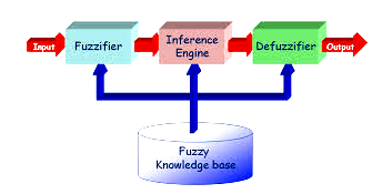
Figure 6.Fuzzy inference system
Figure 7 demonstrates the block diagram of fuzzy logic controller that is intended to control the DC-DC power converter with respect to MPPT of a photovoltaic system. Referring to Figure. 7 the inputs (error (e) and the difference in error (de) of the system are defined as follows [10] :
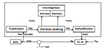
Figure 7.Fuzzy logic controller diagram
![]()
![]()
Knowing that U ref = reference output voltage, U0= DC–DC converter actual output voltage (at kth sampling time).
The fuzzy logic controller (FLC) output is considered as a change in duty ratio; du (k).
Where, duty ratio d (k), is expressed at the kth sampling time as follows:![]()
A more detailed structuring of a fuzzy logic controller is shown below in figure 8.
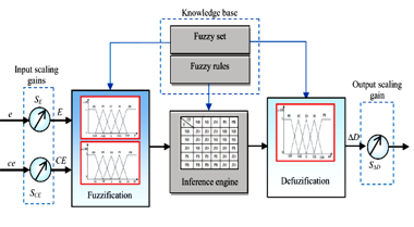
Figure 8. FLC detailed structuring
- Simulations and results for FLC and P&O MPPT techniques
A new adaptation and simulation of a PV system using fuzzy logic controller with an MPPT is addressed. As shown in figure.8, the input variables (E, CE) of the fuzzy controller are resulting from the actual signals (e, ce) through applying a product term in consequent scale gains (SE, SCE), which get converted in the form of linguistic variables utilizing fuzzy subset.
A sample of fuzzy rules are shown in table 1 and used to control the buck converter in a form to reach the maximum power point MPP of the photovoltaic PV generator, where the entries are a sort of fuzzy sets in the form of error (E), change of error (CE) and change of duty ratio (ΔD) to the converter.
Table 1. Fuzzy rules
| E | CE | ||||
| NB | NS | ZO | PS | PB | |
| NB | ZO | ZO | NB | NB | NB |
| NS | ZO | ZO | NS | NS | NS |
| ZO | NS | ZO | ZO | ZO | PS |
| PS | PS | PS | PS | ZO | ZO |
| PB | PB | PB | PB | ZO | ZO |
Figure 8 shows an approach for a main PV model structure composed of PV array, a DC-DC converter in the form of buck or step down converter along with MPPT controller which is connected to a load. This setup is manipulated inside the Matlab/simulink setting. Sunntech STb134.12/Tp represented the PV and its technical data is showing in table 2. Six PV modules connected in series formed the PV array which its total capacity is 810 W. The 105v DC input voltage was stepped down to 48v to fit the battery voltage level using a buck converter [11-14].
In addition, and to implement the fuzzy logic controller FLC, FL toolbox in Matlab/Simulink will be selected and the simulation of fuzzy logic controller for MPPT to be conducted and as we progress an evaluation comparison with a Perturb & Observe (P&O) for MPPT controller was performed.
Table 2.PV module specs
| Electrical specifications | Values |
| Open-circuit voltage | 22.3 V |
| Short-circuit voltage | 8.20A |
| Optimum operating voltage (Vmpp) | 17.5 V |
| Optimum operating current (Impp) | 7.71A |
| Maximum power at STC (Pmax) | 135W |
| Current temperature coefficient of Isc | (0.055 0.01) %K |
| Voltage temperature coefficient | -(75 |
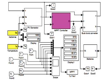
Figure 8a. Simulink implementation of the stand-alone PV system
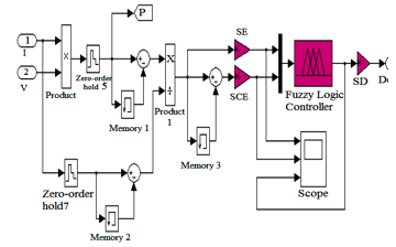
Figure 8b. FLC MPPT algorithm
Figure 9 demonstrates the outcome of the simulation result of PV generator O/P power, operating current & voltage, and eventually the duty ratio “D” through the use of a buck converter and these results were obtained at a standard test conditions (STC) among the fuzzy logic controller “FLC” and the P&O based MPPT. To take the discussions a step forward obviously the outcome of the FLC MPPT had reduced clearly the response time of the PV system. On the other hand as we compare the above to P&O MPPT system P&O showed an impact of energy losses. Figure.9b is derived from comparing the MPPT signals at a frequency of 10HZ “STC”. As we used the P&O technique there was an evidence of a continuous oscillation at the operation point and this was due to the incessant perturbation that took place at the operating voltage to reach the maximum power point “MPP”. As compared to the FLC technique such oscillation wasn’t existing in FL based MPPT technique, whereas the signals of the other parameters which were namely the power “P”, voltage “V”, current “I”, and duty ratio “D” continued to stay constant, which would cause an impact on the reduction of power loss.
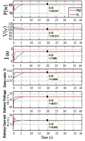
Figure 9a. Comparing P&O and FL signals
Figure 11 displays the simulation of the increase in cell temperature from “25°C” to “50°C” which was taking place at a “2 sec” time period.
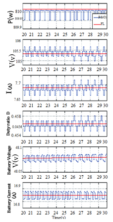
Figure 9b.Comparing MPPT methods at 10Hz frequency at the
(STC) condition
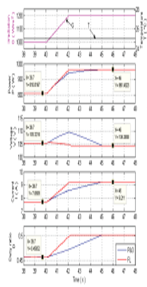
Figure 10. FL and P&O methods at fast increasing irradiation
From the simulation results we can clearly see that irradiation stayed constant on a 1000w/m2 value. In nutshell, Figure 11 shows that the output power with a decreased linearity as we applied both MPPT algorithms namely the fuzzy logic and Perturb and Observe. At the same time P&O MPPT method resulted in low deviation from the maximum power point MPP.
- Conclusion
The employment of MPPT for PV stations and their applications were addressed in the form of two schemes; a first scheme was an adaptation of a model predictive control (MPC) for a PV station that is considered to be a promising technique to maximize the efficiency of the power utilization.
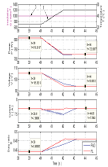
Figure 11. FL and P&O methods at fast increasing temperature
The second scheme of the paper was focusing on the implementation and simulation of fuzzy logic controller for MPPT to seek the maximum power point and comparing it to P&O. From the simulation results, FLC provided a reliable response as compared to the P&O controller in regards to main performance of MPPT.
- Elzein Imad, Petranko Yury. An Integration of a Predictive Control Model and MPPT for PV Station.IEEE Region 8, International Conference on Smart Systems and Technologies (SST 2016), proc. Of IEEE trans., Croatia, IEEE xplorer, region 8, pp. 275-280, ISBN: 978-1-5090-3718-6, IEEE catalog number: CFP16G03-PRT
- Sotnikova MV. Development toolkit for solving control problems with non-linear predictive models in MATLAB Tr. V Int. Conf. “Design of engineering and scientific applications in the environment MATLAB”, 2011, p. 299-319.
- Veremey EI, MV Sotnikova, Plasma stabilization on the basis of the forecast of a steady linear approximation, St. Petersburg. Univ. Ser. 10. 2011, Vol. 1, p. 116-133.
- Sotnikova MV, Questions of stability of motion in control systems with predictive models, Bulletin of Voronezh State Technical University, 2012, p. 72-79.
- MargaritaV. Sotnikova, Evgeny I. Veremey. Dynamic Positioning Based on Nonlinear MPC, IFAC Proceedings Volumes (IFAC-Papers Online). Proceedings of the 9th IFAC Conf. on Control Appl. in Marine Systems (CAMS 2013). Osaka, Japan, September 17-20, 2013, Volume 9, Issue PART 1, 2013, Pages 37-42.
- Nevzat Onat. Recent Developments in Maximum Power Point Tracking Technologies for Photovoltaic Systems. International Journal of Photo energy, Vol. 2010, Article ID 245316, 11 pp., doi:10.1155/2010/245316.
- Elzein, I. Maximum Power Point Tracking System for Photovoltaic Station: a Review. System Analysis and Applied Information Science, No. 3, 2015, pp.15-20.
- D. P. Hohm and M. E. Ropp, “Comparative study of maximum power
point tracking algorithms using an ex- perimental, programmable, maximum power point track- ing test bed,” in Proc. Photovoltaic Specialist Conference, pp. 1699–1702, 2000. - K. H. Hussein, I. Muta, T. Hoshino, and M. Osakada, “Maximum power point tracking: an algorithm for rapidly chancing atmospheric conditions,” IEE Proc.-Gener. Transm. Distrib., Vol. 142, pp. 59–64, 1995.
- Mattavelli, P., Rossetta, L., Spiazzi, G., &Tenti, P. General purpose fuzzy logic controller for DC-DC converters. IEEE Transactions on Power Electronics, 12(1), 1997, pp. 79-85.
- E. Koutroulis, F.Blaabjerg, “ A New Technique for Tracking Global Maximum Power Point of PV Arrays Operating Under Partial-Sheding Conditions” IEEE JORNAL OF PHOTOVOLTAICS, vol. 2, no.2, April 2012.
- Petrenko, Y.N. Fuzzy logic and genetic algorithm technique for non-liner system of overhead crane / Y.N. Petrenko, S.E. Alavi. Computational Technologies in Electrical and Electronics Engineering (SIBIRCON), 2010 IEEE Region 8 International Conference, 11-15 July 2010. pp. 848 – 851.
- Hassan, S.Z.; Li, H.; Kamal, T.; Arifofilu, U.; Mumtaz, S.; Khan, L. Neuro-Fuzzy Wavelet Based Adaptive MPPT Algorithm for Photovoltaic Systems. Energies 2017, 10, 394.
- S. Z. Hassan, H. Li, T. Kamal, M. Nadarajah and F. Mehmood, “Fuzzy embedded MPPT modeling and control of PV system in a hybrid power system,” 2016 International Conference on Emerging Technologies (ICET), Islamabad, 2016, pp. 1-6. doi: 10.1109/ICET.2016.7813236