Collision avoidance between a wheelchair front wheels and a step wall during step climbing using a care robot
Collision avoidance between a wheelchair front wheels and a step wall during step climbing using a care robot
Volume 2, Issue 3, Page No 732-740, 2017
Author’s Name: Hidetoshi Ikeda1, a), Kazuki Hashimoto2, Daisuke Murayama2, Rikuto Yamazaki2, Eiji Nakano3
View Affiliations
1Department of Mechanical Engineering, National Institute of Technology, Toyama College, Toyama, 939-8630, Japan
2Department of Electrical and Control Systems Engineering, National Institute of Technology, Toyama College, Toyama, 939-8630, Japan
3Robofesta org., Tsukuba, 300-2636, Japan
a)Author to whom correspondence should be addressed. E-mail: ikedah@nc-toyama.ac.jp
Adv. Sci. Technol. Eng. Syst. J. 2(3), 732-740 (2017); ![]() DOI: 10.25046/aj020393
DOI: 10.25046/aj020393
Keywords: Robot, Wheelchair, Step climbing collision, Avoidance step wall

Export Citations
This paper discusses a step climbing strategy using a wheelchair and a teleoperated care robot that avoids collisions between the wheelchair’s front wheels and the step wall. In our method, the two vehicles are connected and use the velocity difference between them to climb steps. Since the wheelchair’s front wheels, or another part of the wheelchair, tend to collide with the step being mounted while the wheelchair front wheels are in the lifted position, we investigated a system that permits switching between teleoperation and autonomous control to avoid this problem. In our proposed system, the wheelchair step climbing process is performed under autonomous control, while the robot step climbing process is performed under teleoperation control by a remote caregiver. Theoretical analysis and accompanying calculations were performed to clarify the most suitable lifting position for wheelchair front wheels when climbing, and our experimental results show the overall effectiveness of this system.
Received: 27 April 2017, Accepted: 06 June 2017, Published Online: 16 June 2017
1 Introduction
This paper is an extension of work originally presented in The 2016 IEEE International Conference on Simulation, Modeling, and Programming for Autonomous Robots [1].
For disabled people, using wheelchairs is an effective means for locomotion. However, since it is difficult for wheelchairs to negotiate steps, user movements are often restricted. Some reasons for the wheelchair’s difficulty include driving wheel slippage and/or vehicle imbalance. Numerous research programs aimed at improving wheelchair mobility on steps have been conducted, and the following potential solutions have been investigated: additional legs [2], multiple wheels and variable wheelbases [3], a combination of an adjustable center of gravity (COG) and multiple wheels [4], tracked vehicles [5], an additional driving wheel system [6], and changing the wheelchair posture to facilitate climbing [7]. In addition, Yoshikazu Mori studied a new step climbing and descending strategy using a manual wheelchair equipped with linear actuator mechanisms and a light portable ramp [8].
This study’s research group has previously investigated a cooperative step climbing method that can be used by a robot and a manual wheelchair connected via a passive link [9], and by using a teleoperated robot controlled by a caregiverthroughan intranet and a conventionalor electric drive wheelchair [10][11]. Our step climbing system, which is capable of reducing the burden imposed on the caregiver, takes advantage of the wheelchair user’s ability to judge external information (e.g., obstacles and distances between vehicles and steps), and the caregiver’s ability to teleoperate the system through an intranet.
To operate this step climbing system, both the wheelchair user and the caregiver will need sufficient training, particularly for the period when the wheelchair’s front wheels are close to the step, which is where the risk of a collision between the wheels and step is high. Furthermore, since this system uses autonomous control during the wheelchair step climbing process, it was necessary to implement a support system that can switch between teleoperation and autonomous control.
While the primary purpose of this paper is to describe our proposed support system for avoiding collisions between the wheelchair front wheels and step during stair ascents [1], we will also describe the concept behind our step climbing method, and provide a detailed theoretical analy-
Other reports of multiple vehicles cooperating to cross
Based on our preliminary measurements of the friction coefficients for the robot under wet and dry conditions on asphalt, concrete, wood, and interior flooring, the ground surface considered in this research was assumed to have a friction coefficient within the range of 0.6 to 0.9. The heights of steps located at the entrances of typical buildings and other structures were also measured, and a target step height of 120 mm, which accounts for more than 80% of the observed heights, was set.
This remainder of this paper is organized as follows: Section 2 describes the concept of cooperative step climbing, and Section 3 describes the robot and wheelchair used. Section 4 describes the step climbing process, and Section 5 provides a theoretical analysis of our proposed method. Section 6 describes an experiment using our proposed system and the results, and our conclusion is given in Section7.
2 Concept behind wheelchair care robot
As described above, since it is difficult for wheelchairs to climb steps, wheelchair user movements tend to be restricted. Most wheelchairs have two casters employed as front wheels and two driving rear wheels, and the center of gravity of a wheelchair with a seated user is high. Thus, when a wheelchair attempts to climb a step, high potentials for driving wheel slippage (Figure 1 (a)) and/or tipping over the vehicle (Figure 1 (b)) arise. In addition to step climbing situations, wheelchair users face difficulties at numerous other times. For example, it is difficult for a wheelchair user to open a door (Figure 2 (a)) or pick up an object that is on the floor or placed on a high shelf (Figure 2 (b)). Thus, under most current circumstances, most wheelchair users need a human assistant. However, taking care of a wheelchair and its user is hard work.
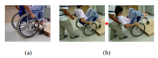 Figure 1: Reasons why wheelchairs are weak against steps: (a) driving wheel slippage, and (b) possibility of tipping over when the rear wheels transverse the step
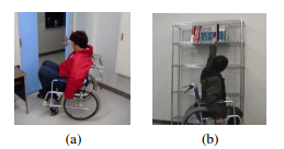 Figure 2: Obstacles for wheelchair users other than step climbing: (a) door opening, and (b) picking up objects
The aim of this research is to create a teleoperated robot system that can be used by caregivers to provide assistance to vulnerable but esteemed persons (such as their elderly parents) from a distant location. In the next section, we will begin by evaluating a method for avoiding collisions between the front wheels of a wheelchair and a step wall.
3 Wheelchair and robot
The robot used in this research is “Tateyama”, which is a wheeled robot developed in this laboratory (Figure 3).
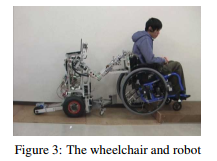 Figure 3: The wheelchair and robot
Table 1: Robot specifications
| Overall length | 230 to 800 mm |
| Overall height | 747 mm |
| Radius of front wheels (rBf ) | 25 mm |
| Radius of middle wheels (RB) | 145 mm |
| Radius of rear wheels (rBr) | 19 mm |
| Wheelbase (WBf) | 190 to 440 mm |
|
Wheelbase (WBr) Distance of center of gravity from |
270 mm |
| the middle wheel axes (lrB) Height of the mass above | 93 mm |
| the middle wheel axes (hmB) Distance of Joint 2 | 286 mm |
| from the rear axes (lLB) Height of Joint 2 | 90 mm |
| above the rear axes (hLB) | 532 mm |
|
Mass of the robot’s body Mass of upper links |
55 kg |
|
(from Joint 2 to 4) Mass of forearm links |
2.55 ×2 kg |
| (form Joint 4 to hand) | 0.8 ×2 kg |
| Length of Link 2 (l2) | 330 mm |
| Length of Link 4 (l4) | 300 mm |
| Length of the hand (l6) Length from Joint 4 | 105 mm |
| to the connecting position (l4C) | 370 mm |
Overall length 1060 mm Overall height 985 mmTable 2: Wheelchair specifications
Radius of front wheels (rA) 63 mm
Radius of rear wheels (RA) 300 mm
Wheelbase (lA) 430 mm
Hand rim position (lLA) 250 mm
Distance of center of gravity from
the rear wheel axles (lrA) 149 mm
Height of mass above
the rear wheel axles (hmA) 371 mm Height of push-handle (hLA) 435 mm
Mass (wheelchair + driver) (MA) 92.7 kg
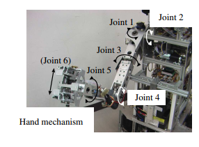 Figure 5: Robot manipulator
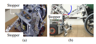 Figure 6: Rotary motion control of the robot shoulder using the robot body: (a) Front body of the robot, and (b) side view of stopper on the robot chest
The process begins with the wheelchair and robot deployed in a forward-and-aft configuration to traverse the step (Figure 4). When the wheelchair and the robot encounter a step, the robotic hands grasp the rotary shaft of the wheelchair push handle [14]. Table 1 and Table 2 list the specifications of the robot and wheelchair, respectively. The wheelchair and robot move at a constant speed (0.76 km/h). This robot is equipped with three pairs of wheels, and each pair consists of left and right wheels. The front pair are casters, whereas the middle and rear pairs are driving wheels. The front and rear pairs can be folded.
 Figure 7: Human pushing an object
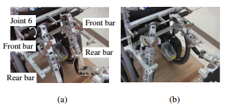 Figure 8: Sides of the robot: (a) in wheelchair climbing position, and (b) in robot climbing position
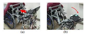 Figure 9: Stopper actions: (a) lifting the robot wheels, and (b) preventing the robot from falling down
The robot has manipulators attached to the left and right joints of its upper half. Since each arm has five degrees of freedom (5-DOF) and the hand has 1-DOF, the arm has a total of 6-DOF (Figure 5). In this paper, the length of the upper arm link (from Joint 2 (shoulder) to Joint 4 (elbow)) is l2; the length of the forearm link (from Joint 4 to Joint 6) is l4C. The manipulator joint angles are −90 deg ≤ φ2 ≤ +90 deg and 0 ≤ φ3 ≤ +100 deg. The right and left hands each have two fingers (Joint 6) in order to grasp and hold items (Figure 5).
|
|
The robot is equipped with a stopper mounted on the front part of its body (Figure 6 (a)), as described below, and is capable of limiting the passive rotational travel of the manipulators when it is pushing the wheelchair (Figure 6 (b)). This enables the robot to imitate the operation of a human pushing an object (Figure 7). The robot does not need to exert force around the shoulder axes because its upper arms push against the chest (i.e., the stopper) when pushing the wheelchair [11]. The motors mounted on the robot are connected to Faulhaber MCDC3003-S and MCDC3006S motion controllers (Faulhaber-Global, Schnaich, Germany). These are connected to a notebook personal computer (PC) mounted on the robot. The shape of the IntegralME wheelchair (NOVA, Carson, Ca) used in this study is typical among wheelchairs available on the market (Figure 3). The rear-wheel drive wheelchair is equipped with a TRD-1 electric drive unit (Acritech Co., Ltd.). Two motion controllers are added for the electric drive unit. The motion controllers on the wheelchair are connected to the notebook PC installed on the robot via a ZigBee wireless communications module. The wheelchairhas a push handle mechanism on its back (Figure 8 (a)) that is equipped with a rotary shaft in order to permit passive rotation of the handle. When the robot hands grasp this shaft, the two vehicles are connected. The stopper of the wheelchair is composed of front and rear bars. During the robot climbing process, the sides of the robot are opened, and the right and left manipulators are inserted into the stopper (Figure 8 (b)). The dual manipulators of the robot are equipped with touch sensors that allow them to detect contact with the stopper. The robot pushes the front bars by using the forearm links of the manipulators to lift its front wheels (Figure 9 (a)). The rear bars are used to prevent the robot from tipping over backward when its center of gravity shifts behind the contact point between the middle wheels and the ground (Figure 9 (b)).
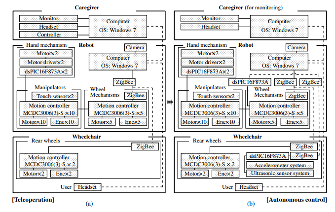
The robot control mode can be switched between network-basedteleoperationand autonomouscontrol by the caregiver. In Figure 10, (a) is a system configuration diagram that shows the working device in the teleoperation mode, and Figure 10 (b) shows the system diagram of the autonomous control mode. These system configuration diagrams show only the working devices in each mode. When engaged in wheelchair step climbing, this system uses the autonomous control. For robot step climbing, the system uses the teleoperation mode.
3.1 Teleoperation
The robot is equipped with a camera, and the video imagery transmitted from it and the Motion Manager 5 operating window are displayed on the robot’s notebook PC. The screen on this notebook PC uses RealVNC (RealVCN Ltd., Cambridge, UK) software to transmit imagery as-is over the intranet to the display of the caretaker’s PC (robot operator). The caregiver can control the robot by operating Motion Manager 5 (Faulhaber-Global)from his PC. The caregiver and the wheelchair user both wear headsets. The caregiver’s headset is connected to his/her PC, and the chair user’s headset is connected to the robot PC via Bluetooth. The caregiver and the wheelchair user verbally telecommunicate via the Skype (Microsoft Corp., Redmond, Wa) communication application. Keyboard commands, which are activated by pushing the buttons of a joypad, correspond to the controller manipulations necessary to teleoperate the robot. Switching between teleoperation and autonomous control is carried out by the controller.
To lift the front wheels of the wheelchair, the robot stops while the wheelchair drive continues moving (see Section 4). However, network teleoperation is difficult for this process because the wheelchair’s raised front wheels tend to collide with the step when they are in near proximity with each other (Figure 11).
3.2 Autonomous control
An accelerometer system and an ultrasonic sensor system were added onto the chair, and a support system for the caregiver was created. The accelerometer system detects the incline of the chair, and the ultrasonic sensor system measures the distance between the chair and the step.
Both sensor systems are connected to the robot’s PC by a ZigBee wireless communication module. Since the support system for the caregiver is capable of performing the wheelchair step climbing process automatically, the caregiver (robot operator) does not need to control the vehicles in the autonomous control mode. However, the caregiver can watch the live video from the robot’s camera, and the wheelchair user and the caregiver are in direct verbal communication, so if the vehicles encountera problem,the caregiver switches from autonomous to teleoperation control to handle it.
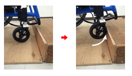 Figure 11: Collision between the front wheels and step
4 Step climbing process
When the vehicles encounter a step, the robot hands grasp the rotary shaft of the wheelchair’s push handle mechanism, thus linking the two vehicles [14]. Joints 2, 4, and 6 are allowed to rotate passively (Figs. 5 and 8). In this study, Stages 1 and 2 signify the processes in which the wheelchair front and back wheels, respectively, ascend the step. Similarly, Stages 3 and 4 signify the processes in which the robot front and other wheels, respectively, climb the step.
Both vehicles move automatically during the wheelchair step climbing process (Stages 1 and 2) by using the caregiver’s support system. After that, the caregiver switches from autonomous control to teleoperation, and the robot step climbing process (Stage 3 and 4) is carried out. The ascent process is described below (the states shown in Figure 12 correspond to (1) through (16) below.
[Stage 1]
(1) From Stage 1 to Stage 2, the vehicles are under autonomous control. The wheelchair and the robot move forward until the ultrasonic sensor system detects a suitable position where the wheelchair front wheels do not collide with the step. (2) The robot stops and the wheelchair continues forward until the accelerometer system detects the wheelchair inclination level that would place the front wheels on the step. (3) At this point, the wheelchair center of mass is in front of the contact point between the rear wheels and the ground. If it shifts to behind the contact point as the wheelchair tilt increases, the stopper of the robot limits the passive rotation around Joint 2, which prevents the wheelchair from tipping over backward (Figure 6 (b)). (4) Both vehicles move forward, and the front wheels of the wheelchair are placed on the step.
[Stage 2]
(5) Both vehicles continue to move forward. (6) The back wheels of the wheelchair come into contact with the step. (7) The robot continues to push the wheelchair so that the rear wheels of the wheelchair climb up onto the step. The robot supports the wheelchair during this process to prevent the wheelchair from tipping over backward. (8) Both vehicles move forward, and the wheelchair’s rear wheels climb the step.
After the wheelchair’s rear wheels have reached the upper level of the step, the robot control mode is switched from autonomous to teleoperation control by the caregiver. The caregiver directs the vehicles to stop.
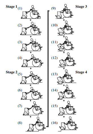 Figure 12: Step climbing process (Stages 1 through 4)
[Stage 3]
(9) The robot’s front and rear wheels are folded, its
sides are opened, and the manipulator forearm links are inserted into the wheelchair stopper (Figs. 8 (a) and (b)). The wheelchair stops while the robot moves forward, and the manipulator forearm links comes into contact with the front bars of the wheelchair stopper (Figure 9 (a)). (10) The robot continues to push the wheelchair using the forearm links, and the front wheels of the robot are lifted. (11) When the robot center of mass shifts behind the contact point between its middle and the ground, the robot’s tilt increases and it begins to tip over backward. However, at that point, part of the manipulator forearm links come into contact with the rear bars of wheelchair stopper, which limits the extent of rotation (Figure 9 (b)). Thus, the wheelchair prevents the robot from tipping over backward. (12) Both vehicles move forward, and the front wheels of the robot are placed on the upper level of the step.
[Stage 4]
(13) Both vehicles continue to move forward. (14) When the robot middle wheels come into contact with the step, the wheelchair pulls it forward. The robot rear wheels are lowered and provide climbing help. Then, the robot middle wheels begin to climb the step. (15) Both vehicles continue to move forward. (16) The robot middle wheels can now climb the step. Once the robot middle wheels have reached the upper level of the step, both vehicles are stopped, and the robot’s rear wheels are folded upward.
5 Theoretical Analysis
When the distance between the step and the wheelchair is too short to lift the front wheels, the wheels will collide with the step (Figure 11). In this section, we clarify the requirement for avoiding a collision between the chair front wheels and the step.
In Figure 13, ΣB is the basic coordinate system for the robot and wheelchair, where p0 is the origin as well as the contact position between the robot middle (driving) wheels and the ground. The position of the step edge is pse, where pi (i = 1–7) are the joints (p1: axes of the robot middle wheels, p2: shoulder joints, p3: elbow joints, p4: robot hands (location where the hands hold the wheelchair push handle), p5: axes of the wheelchair rear wheels, p6: axes of the wheelchair front wheels and, p7: the tread of the wheelchair front wheels).
The position vectors for the joints in system ΣB are expressed as B pi = [xi zi]T (i = 1 − 7). The position vectors of the step edge are B pse = [L h]T.
In the local coordinate system, in the case that Σi parallels Σ0, 0p1 = [0 RB]T, 1p2 = [lLB hLB]T, 2p3 = [l2 0]T,
3p4 = [l4C 0]T, 4p5 = [lLA −hLA]T, 5p6 = [lA −RA +rA]T, and 6p7 = [rA 0]T (Figure 13).
Moreover, φi is the angle of Σi formed by Σi−1. In this system, φ1 is zero in Stage 1 because Σ1 parallels Σ0, and φ3 is zero when the wheelchair is pulled by the robot because the elbow joints are controlled passively. In addition, φ5 = 0 is always zero because Σ5 parallels Σ4. Hence, the wheelchair inclination is Σ5k=1φi = φ2 + φ4.
ΣB(Σ0)
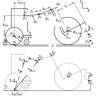 Figure 13: Wheelchair and robot model
In the basic coordinate system ΣB, the homogeneous transformation matrices BT5, BT6 are given below.
| BT5 : cossin0φφ2424 BT6 : cossin0φφ246246 |
−sinφ24 cosφ24 0 −sinφ246 cosφ246 0 |
yx155 yx166 |
(1) (2) |
Here, φ24 = φ2 + φ4, φ246 = φ2 + φ4 + φ6. Equations (3) and (4) show the positions of the wheelchair rear and front wheels axes, B p5 = [x5 y5]T, B p6 = [x6 y6]T, respectively.
B p5 : ” x5 # = ” cosφ24 −sinφ24 #” lA # y5 sinφ24 cosφ24 −hLA
+ (l2 + l4C)cosφ2 # + ” lLB # (3) sinφ2 hLB + RB
B p6 : ” x6 # = ” cosφ24 −sinφ24 #” lA + lLA # y6 sinφ24 cosφ24 rA − RA − hLA
+ (l2 + l4C)cosφ2 # + ” lLB # (4) sinφ2 hLB + RB
Similarly, from a calculation of the transformation matrix BT7, B p7 = [x7 y7]T is given below.
B p7 : ” x7 # = rA ” cosφ246 # y7 sinφ246
+cosφ24 −sinφ24 #” lA + lLA # sinφ24 cosφ24 rA − RA − hLA
+ (l2 + l4C)cosφ2 # + ” lLB # (5) sinφ2 hLB + RB
Here, when B p7 is the bottom position of the wheelchair front wheels, Σ6k=1φi = −90 deg. Hence, cosφ246 = 0 and sinφ246 = −1.
Meanwhile, y5 = RA in Stage 1 because y5 is the height of the wheelchair rear wheel axes (Figure 13). Hence, Equation (6) is obtained from (3).
lLA sinφ24−hLA cosφ24+(l2+l4C)sinφ2+hLB+RB = RA (6)
Thus,
hLA cosφ24 − lLA sinφ24 + RA − RB − hLB
sinφ2 = (7)
l2 + l4C
and
cosφ2 = q1 − sin2 φ2 (8)
Equation (6) is substituted for y7 of (5) when B p7 is the bottom of the front wheels.
y7 = −rA + lA sinφ24 + (−RA + rA)cosφ24 + RA (9)
where
sinφ24 = q1 − cos2 φ24 (10)
From Equations (9) and (10), we obtain Equation (11).
cosφ24
(RA − rA)(RA − rA − y7) + lA p2(RA − rA)y7 + lA2 − y72
=
(RA − rA)2 + lA2
(11)
We substitute y7 = h for Equation (11) if the system detects the step height h, and can then ascertain the necessary minimum inclination of the wheelchair in order to put the front wheels on the step.
When the height of the front wheel axes is lower than the step height, the requirement needed to avoid a collision between the wheelchair front wheels and the step is Equation (12) (Figure 14 (a)).
kB ps −Bp6k > rA (0 < x6 < L, 0 < y6 < h) (12)
Here,
B T
ps = [L y6] (13)
is a vector whose horizontal position is on the step wall (L), and the height is the same as the wheelchair front wheel axes (y6).
Similarly, when the front wheel axes are above the step, Equation (14) shows the requirement to avoid a collision (Figure 14 (b)).
kB pse −Bp6k > rA (0 < x6 < L, h ≤ y6) (14)
Then, using Equations (12) and (14), the system avoids a collision between the wheelchair front wheels and the step by detecting the chair inclination (φ2 + φ4), the distance from the step (L), and the step height (h).
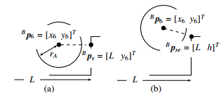 Figure 14: Collision between the front wheels and a step.
(a) 0 ≤ y6 ≤ h, (b) h < y6
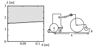 Figure 15: Step height and distance capable of avoiding
collision
The requirement for avoiding a collision between the wheelchair front wheels and the step (Equation (12), Figure 14 (a)) is more difficult than the case where the front wheel axes are above the step (Equation (14), Figure 14 (b)). Thus, we performed a numerical calculation to clarify the lifting position of the front wheels using Equation (12). Equation (12) is solved using (4), (7), (8), (10), (11), and (13). Here, y7 is the minimum bottom height of the front wheels (Figure 13) needed for the system to lift the wheels up to the step height (h).
Substituting y7 = h for Equation (12), the shading in Figure 15 shows a combination of the step height (h) and the distance (L) that enables it to avoid the collision, where the horizontal axis indicates h (step height) and the vertical axis indicates L (distance from the robot’s rear wheel axes to the step wall). By selecting the distance (L) in the shadings when the step height is (h), the wheelchair front wheels can avoid collision during climbing.
6 Experiment
An experiment was carried out in a situation involving a step 120 mm high and a friction coefficient µ = 0.72. The wheelchair user was on one floor of the National Institute of Technology, Toyama College, and the caregiver (robot operator) was on another floor. The movement speeds of the vehicles were constant (0.76 km/h). The wheelchair user and the robot operator were both able-bodied adult males. We assumed that the system knew the step height was below 120 mm.
In Stages 1 and 2, when using autonomous control, the wheelchair front wheels did not bump into the vertical wall of the step and the front wheels and rear wheels were able to traverse the step successfully (Figure 16). Here, L = 2.07 m. Operation changed from autonomous to teleoperation control following Stage 2, and the caregiver was able to move the robot forward into a suitable position for climbing the step. Next, the robot successfully climbed the step (Stages 3 and 4). In Stages 3 and 4, the system was operated by the caregiver who was watching video imagery from the robot’s camera. However, the operation was difficult because the robot inclined during its step climbing process and the mounted camera lost sight of the wheelchair. This and other experiments have shown that we need to construct a fully autonomous control system that can handle robot climbing as well as wheelchair climbing.
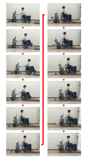 Figure 16: Step climbing experiment
7 Conclusion
This report describes a support system for a robot operator that can be used to perform wheelchair step climbing. The support system was designed and constructed in a way that permitted switching between teleoperation and autonomous control. We then conducted a theoretical analysis to show the requirements for preventing the wheelchair’s front wheels from colliding with the step, which involved a numerical calculation to clarify the position for lifting the wheelchair’s front wheels.
In experiments carried out with the system, autonomous control for wheelchair step climbing and teleoperation control for robot step climbing were both demonstrated to be effective. However, teleoperation control by a caregiver was complicated by the need to watch video imagery from the robot camera. This indicates that the system needs autonomous control system for the robot as well.
Nevertheless, it is notable that our theory for collision avoidance between the step wall and wheelchair’s front wheels during the step climbing was confirmed, and that both vehicles were able to climb a step using the theory and system.
In the future, we will construct a fully autonomous control system will be able to perform step climbing for both the wheelchair and the robot, and we will analyze a suitable step climbing trajectory for both vehicles.
Acknowledgment This research has been supported by the Kayamori Foundation of Informational Science Advancement (K25 XVII 430).
- H. Ikeda, K. Hashimoto, D. Murayama, R. Yamazaki and E. Nakano, “Robot teleoperation support system for collision avoidance between heelchair front wheels and a step”, Proceedings of The 2016 IEEE International conference on Simulation, Modeling, and Programming for Autonomous Robots, 203-209, 2016.
- V. Kumar and V. Krovi, “Optimal Traction Control In A Wheelchair With legs And Wheels”, Proceedings of the 4th National Applied Mechanisms and Robotics Conference, 95-030-01 – 95-030-07, 1995.
- A.Gonzalez, E.Ottaviano and M.Ceccarelli “On the Kinematic Functionality of s Four-bar Based Mechanism for Guiding Wheels in Climbing Steps and Obstacles,” Mechanism and Machine Theory, 44, 1507-1523, 2009.
- Independence Technology, L.L.C., iBOT, http://www.ibotnow.com/, 2008.
- K.Sugiyama, T.Ishimatsu, T.Shigechi and M.Kurihara “Development of Staeir-climbing Machines at Nagasaki”, Proceedings of the 3rd International workshop of Advanced Mechatoronics, 214-217, 1999.
- Y.Munakata and M.Wada, “Modeling and analysis of static wheelie of a five-wheeled wheelchair for climbing over a step”, Proceedings of IEEE/ASME International Conference on Advanced intelligent Mechatoronics, 1006-1011, 2014.
- M.Lawn and T.Ishimatsu, “Modeling of a Stair-Climbing Wheelchair Mechanism with High Single Step Capability. IEEE Transactions on Neural Systems and Rehabilitation Engineering”, 11(3), 323-332, 2003.
- Y. Mori, K. Katsumura, and K. Nagase. “A pair of step- climbing units for a manual wheelchair user: Passing over several steps using a pair of portable slopes”, Advances in Mechanical Engineering, 9(3), 1-11, 2017
- H.Ikeda, Y.Katsumata, M.Shoji, T.Takahashi and E.Nakano “Cooperative strategy for a wheelchair and a robot to climb and descend a step,” ADVANCED ROBOTICS, 22, 1439- 1460, 2008.
- H.Ikeda, H.Kanda, N.Yamashima and E.Nakano, “Step climbing and Descending for a Manual wheelchair with a Network care robot,”Proceeding of The Second International Conference on Intelligent System and Applications, 95-102, 2013.
- H. Ikeda, N. Hatakeyama, A. Kinoshita and E.Nakano, “Step Moving for an Electric Wheelchair Using a Robot Programmable over the Intranet”, Proceedings of 2nd IEEE/SAE/IFAC International Conference on Connected Vehicles and Expo, 791-797, 2013.
- H.Asama, M.Sato, N.Goto, H.Kaetsu, A.Matsumoto and I.Endo, “Mutual Transportation of Cooperative Mobile Robots Using Forklift Mechanisms,” Proceedings of the 1996 IEEE International Conference on Robotics and Automation, 1754-1759, 1996.
- J. Gaston, K.Raahemifar, P.Hiscocks, “A cooperative Net- work of Reconfigurable Stair-Climbing Robots”, Proceeding of 2006 IEEE International Sysposium on circuits and Systems, 4-7, 2006.
- H.Ikeda, N.Yamashima, S.Haruta and E.Nakano, “Docking method for a wheelchair and a care robot using both teleoperation and autonomous control”, International Journal of Machanical Engineering and Robotics Research, 5(2), 82- 89, 2016.