Preparation of Ni-C Ultrafine Composite from Waste Material
Preparation of Ni-C Ultrafine Composite from Waste Material
Volume 2, Issue 3, Page No 695-701, 2017
Author’s Name: Mahmoud A. Rabaha), S.M. Abdelbasir
View Affiliations
Electrochemical Treatment Dept., Mineral Processing Div. Central metallurgical Research and Development Institute (CMRDI) Egypt.
a)Author to whom correspondence should be addressed. E-mail: mrabah010@gmail.com
Adv. Sci. Technol. Eng. Syst. J. 2(3), 695-701 (2017); ![]() DOI: 10.25046/aj020389
DOI: 10.25046/aj020389
Keywords: Carbon Ultrafine Scale, Carbon-Nickel Ultrafine Composite, Plasma Technology, Spent Engine Oil, Plasma Heat Decomposition

Export Citations
This work depicts the preparation of Ni-C ultrafine composite from used engine oil. The used oil was emulsified with detergent loaded with Ni (OH)2. The loaded emulsion was sprayed on electric plasma generated between two C electrodes to a DC main 28 V and 70-80 A. The purged Ni-doped carbon fume was trapped on a polymer film moistened with synthetic adhesive to fix the trapped smoke. Characterization of the deposit was made using SEM. XRD examined the crystal morphology. Carbon density in the cloud was calculated. The average size and thickness of the deposited composite is 120-160 nm. Aliphatic hydrocarbons readily decompose to gaseous products. Solid carbon smoke originates from aromatic compounds. Plasma heat blasts the oil in short time to decompose in one step.
Received: 02 April 2017, Accepted: 15 May 2017, Published Online: 09 June 2017
1. Introduction
Teng [1] reported the use of plasma arc technology to produce fluid of carbon ultrafine particles dispersed in distilled water. Carbon is simultaneously heated and vaporized in a chamber furnace. Carbon vapor was cooled to prepare a carbon/water ultrafine slurry. The problem of heat dissipation from electrical appliances became a significant issue. To ameliorate this problem, there are four approaches commonly taken [2] enlarged the heat exchanger area and structure, [3] fabricated the heat exchanger using materials with higher thermal conductivity, [4] increased the working fluid flow rate to the heat exchanger, and [5] improved the heat transfer performance of the heat exchange working fluid. Akoh [6] prepared superfine fluids using the VEROS method. Teng [7] improved the VEROS technique and developed successful and effective preparation of Ag, Fe fine fluids. Bo [8] showed that plasma-enhanced chemical vapour deposition (PEVCD) has emerged as a key method to generate vapor-gas; and determine the development of VG with required properties. The paper summarized the state-of-the-art research on PECVD growth of VG ultrafine sheets. It provided guidelines on the design of plasma sources and operation parameters. Also to offer a future good challenges that would help commercial applications of VG. The authors studied the influence of feedstock gas temperature and pressure on VG growth. The effect of pretreatment and the growth of VG patterns on cylindrical and carbon ultrafine tube (CNT) substrates was shown. After discussion conclusion showed challenges and future directions for PEVCD growth of VG.
In the year 2014, defects-free graphene and with highest electron mobility was successfully prepared. Mayer [9] used adhesive tape to separate graphene sheets from graphite. It was reported that hydrazine followed by annealing in argon/hydrogen gases was successful to reduce graphite oxide. It was shown that almost intact carbon framework allowed efficient removal of functional groups. Some molten salts attack graphite particles to form a variety of carbon ultrafine structures including graphene [10]. Hydrogen cations, dissolved in molten lithium chloride, were discharged and intercalated and peeled to graphene sheets [11]. The graphene ultrafine sheets produced displayed a single-crystalline structure with a lateral size of several hundred ultrafine meters and a high degree of crystalline and thermal stability [12]. In 2014 defect-free, not oxidized graphene-containing liquids were made from graphite using mixers that produce local shear rates greater than 7005100000000000000♠10×104 [13]. Mubarak [14] reported that the chemical vapor deposition (CVD) had been found a potential way to produce high quality and at high yield of CNTs. El Mel et al., [15]
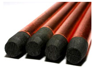
Fig. 1 A photograph of the used carbon electrode
Industrial nitrogen gas was used as a propellant to spray the emulsified oil on the plasma. The gas was supplied in cylinder with the following specifications
Nitrogen and trace inserts 99.998%
Oxygen < 0.001%
Density (g cm-3) 1.2506
Sp. Gravity (g.cm-3) 0.9737
Viscosity (g cm-1s-1) 1.809×10⁻⁴
The chemicals used are technical pure grade. Nickel hydroxide salt was synthetically prepared by precipitation by adding 10% ammonium hydroxide to nickel sulfate solution. The precipitated Ni(OH)2 was filtered, washed and dried.
2. Emulsification of the used engine oil
About 100 g of the used engine oil was placed in a conical flask of a thermostated agitator maintained at 80°C. The flask was fitted with an electrical mechanical stirrer. After the oil has acquired the required temperature, sodium sulphonate detergent containing nickel hydroxide suspended in distilled water was added step wise while stirring for 4 hours. The emulsion was then transferred to a separating funnel and left over night.
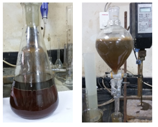
Fig. 2 The engine oil before and after emulsification
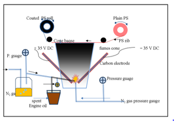
Fig.3 The Electric Plasma device for thermal decomposition of engine oil.
3. Method of preparation of the Ni-doped carbon ultrafine particles.
Determination of the extent of engine oil emulsification was determined by weighing the separated portion of the not emulsified oil. Fig. 2 shows partial (2a) and full (2b) emulsification of the used oil. Fig. 2 her
4. Methods of measurement of the physic-chemical properties
Determination of nickel in the oil suspension or in the prepared composite was carried out by dissolving 1 g of the oil or 250 mg of the catalyst in 1 N nitric acid. Nickel content was determined using spectrophotometer Unicom 7400 Fig.3 shows a schematic diagram of the Electric Plasma device used for thermal decomposition of the engine oil. Particle size and shape of the product were determined using the light-scattering size analyzer, SEM. Crystal morphology was examined by X ray diffraction (XRD).
5. Results
The specifications of the engine oil are given in Table 1. It can be seen that the spent oil has lower viscosity, foam and gelation index and higher phosphorus content.
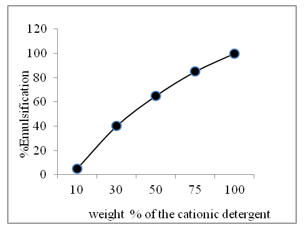
Fig. 4 The emulsification extent of using cationic polymer
Fig. 4 shows the extent of emulsification of the spent engine oil (SEO) as affected by the weight of commercial anionic detergents containing 10 % Ni as Ni(OH)2. It is seen that the extent of emulsification of the spent engine oil increases linearly with the corresponding increase of the detergent. Anionic detergent is far efficient to emulsify engine oil as compared to the cationic detergent to emulsify the spent engine oil.

Fig 5 Effect of detergent type on the extent of emulsification of spent engine oil.
Table 1. The specifications of the engine oil used in this study
| API. SN | API.SN + RC | ||
| Viscosity Grade |
0W20, 0W30, 5W20, 5W30, 10W30 0W8 (spent) |
Others | Multigrade variations of 0W, 5W and 10W |
| Sculpture, max % | 0.5 0.45 | NA | 0.5 |
| High temp. deposits, max mg | 35 46 | 45 | 35 |
| Foam | 1 min settling <1 min | 10 min. settling | 1 min. settling |
| Gelation Index | 12 6 | NR | 12 |
| Emulsion Retention | NA NA | NA | No Water Separation |
| P, max% / min% | 0.08/0.06 0.06 | NA / 0.06 | 0.08 / 0.06 |
Table 2 shows a comparative data on the effect of mass of anionic and cationic polymers as a detergent for emulsifying the used engine oil. It is shown that anionic polymer is more power
Table 2 The effect of mass of the polymer on the emulsification extent of Em. at room temperature
| % emulsification | Anionic polymer | Cationic polymer |
| 20 | 18 | 20 |
| 40 | 30 | 30 |
| 60 | 38 | 50 |
| 80 | 50 | 72 |
| 100 | 60 | 100 |
Fig. 6 shows the rate of discharge of oil from the spraying nozzle as affected by the pressure of propellant nitrogen gas. It is seen that convenient rate of discharge amounting to 2.5-3.0 g/min is achieved with 3 – 3.5 KPa. Such rate was found suitable to generate and decompose the Em. together with the Ns solutioFig. 5 Effect of the pressure of the propellant nitrogen gas on the rate of discharge of the emulsified engine oil
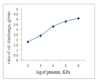
Fig. 6 The rate of the oil discharge from the spraying nozzle as affected by the propellant nitrogen gas
Fig. 7 shows a photograph of the electric plasma generated between the carbon electrodes.
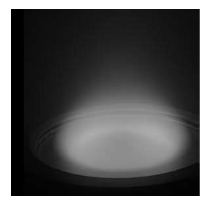
Fig. 7 A photograph of t electric plasma exerted between two carbon electrodes
Table 3 The carbon density in the plasma hood
| No. | Oilg/min. | ∑C, mg/min | H, mm | r, mm at H, mm |
ȓ2 mm2 |
V, cm3 |
Cc, mg/ cm3/min |
Cc, ug/ cm2/min |
||
| Ho | H1 | ȓ | ||||||||
| 1 | 1 | 275 | 100 |
10 20 20 25 30 |
50 60 70 80 90 |
30 40 45 55 60 |
900 1600 2025 3025 3600 |
94.247 167.5 212.0 318.2 375.04 |
2.917 1.642 1.297 0.864 0.7332 |
297 164 129 86.4 73.3 |
| 2 | 1.5 | 412.5 | 175 |
10 20 30 |
50 70 90 |
30 45 60 |
900 2025 3600 |
164.0 369.2 656.3 |
2.515 1.1172 0.6285 |
251 111.7 62.85 |
| 3 | 2 | 550 | 200 |
10 20 30 |
50 70 90 |
30 45 60 |
900 2025 3600 |
187.5 421.9 750.0 |
2.933 1.303 0.7333 |
293.3 130.3 73.33 |
| 4 | 2.5 | 687.5 | 250 |
10 20 30 |
50 70 90 |
30 45 60 |
900 2025 3600 |
234.4 527.4 937.6 |
2.933 1.3035 0.7339 |
293.3 130.35 73.39 |
| 5 | 3 | 825 | 300 |
10 20 30 |
50 70 90 |
30 45 60 |
900 2025 3600 |
281.3 632.9 1125.13 |
2.933 1303.5 0.7332 |
293.3 130.3 73.32 |
Table 3 shows the mean value of the weight of carbon particles disseminated in the cone of a plasma heat as a function of the weight of inserted oil and the dimensions of the cone.
Fig.8 shows the XRD diffraction patterns of nickel-carbon composite species It is seen that the diffraction peaks of Ni confirm the existence of well crystalline Ni metal. Raman spectrum of Ni doping C appeared with ID/IG=0.63
Fig. 9 shows the weight of the deposited carbon -Ni composite on the polymer film as a function of the weight of the sprayed engine oil as a function of the weight of the sprayed emulsified engine oil.
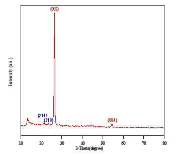
Fig. 8 The XRD diffraction patterns of nickel-carbon composite species It
It can be seen that the weight of the deposited C-Ni amounts to 10 ug/cm2 and increases gradually with the increase of the weight of sprayed engine oil up to 350 mg whereby the maximum WCNIO is attained (45.5 ug/cm2). Fig. 10 shows the SEM of the deposited C-Ni composite material.
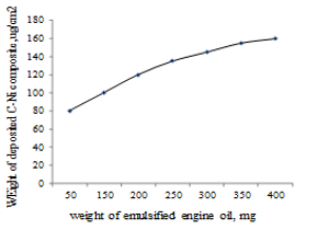
Fig. 9 The weight of the deposited C-NiO (WCNiO)
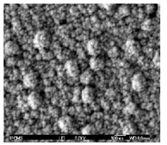
Fig. 10 SEM photograph of the deposited C—Ni composite
1. Mathematical Model
A mathematical model has been proposed to simulate the formation of C-Ni particles in the hood of the plasma heat vicinity based on the following assumptions:
- The chemical analysis of the used engine oil (Ou) and the projected plasma heat at the hood vicinity (hv) are kept constant throughout the experiments.
- Solid carbon particles generate at a constant weight percentage of 27.5 % of the weight of the oil as determined experimentally.
- The weight of carbon generates in nearly no time; Wtc = 0.275 Wto.
- Ejection of the emulsified engine oil takes place in the plasma core at a constant discharge rate for a given driving pressure.
- No extra air was fed into the hood vicinity of the plasma arc
- The carbon particles dissemination is distributed symmetrically at a given horizontal level in the hood.
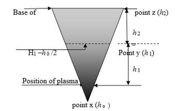
Fig. 11 A Schematic proposal of the caron-Ni smoke in the blasma hook.
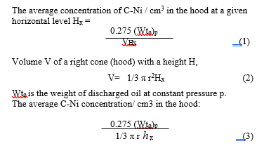
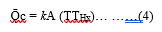
- Carbon particles disseminate in the hood volume under a convection model of heat transfer. Convection above a hot surface occurs because hot air expands and becomes less dense and rises upwards. Convective transfer involves the combined processes of diffusion (conduction) and advection transfer by bulk fluid flow. Natural buoyancy forces alone are entirely responsible for the C-Ni fluid motion upon heating the mass transfer of carbon.Where k is a transfer coefficient, A is the total surface area of the carbon particles, Tp is the temperature at the plasma core and THx is the temperature at the level Hx in the hood. The convective transfer coefficient is dependent upon the physical properties of the fluid (here air). Values of h have been measured and tabulated in the literature for commonly encountered fluids and flow of situations [18]. The mathematical presentation model of the release, development and change of air-born solid fluid (C-Ni particles) as a function of variables such as time, temperature, pressure, distance, and concentration has been processed using “the experimental design” program. Results are under publication elsewhere
Temperature gradient of the plasma heat vicinity comply the curve given in Fig. 12
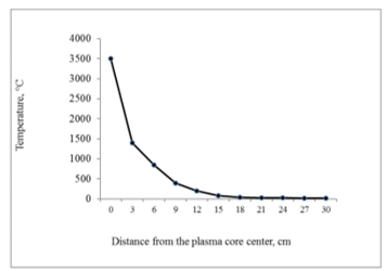
Fig. 12 Temperature gradient of blasma heat as a function of distance
7. Discussion
Engine oil is composed of hydrocarbons, poly alpha olefins (PAO), and poly internal olefins(PIO). The organic compounds consisting entirely of carbon and hydrogen [17]. The oil contains 73-80% weight/weight aliphatic hydrocarbons (primarily alkanes and cycloalkanes with l-6 rings); 11-15% monoaromatic hydrocarbons; 2-5% diaromatic hydrocarbons; and 4-8% polyaromatic hydrocarbons. Additives for lubrication, (≈ 20% of the oil), consist primarily of zinc diaryl, molybdenum disulfide, zinc dithiophosphate, metal soaps, and other organo metallic compounds. The Canadian Environmental Protection Agency reported that up to 15% of the additives are detergents and dispersants [18]. Other used mineral-based crankcase oil may contain compounds of barium, phosphorus, zinc, and some chlorine and bromine as a result of oil additives [18]. Inorganic compounds of sulfur, aluminum, arsenic, calcium, chromium, copper, iron, magnesium, manganese, potassium, silicon, sodium, tin are detected. Organic solvents of toluene, benzene, xylene,and ethylbenzene are present although most of the organic compounds may be destroyed during combustion of crankcase oil as fuel [19]. In general, sources of dirt, sand and dust from the air, soot, contaminate unburned fuel in the motor oil. Water if detected is formed from condensation of the combustion products. Particulates of metal wear that the oil filter cannot trap together with the corrosion by-products and degraded additive elements [20, 21]. All these contaminants enter the engine oil and creat more wear debris and cause more damage than they would separately.
Heating engine oil at high temperatures undergoes a decrease in viscosity grade and degradation reactions of multi sequence order. Decomposition begins with the formation of compounds having more simple molecular chemical formulae. According to the infrared spectra, the paraffinic-naphthenic fractions of new and used oils are substantially similar to each other. The aromatic fractions of the used oil contain oxygen groups that can be removed only by catalytic hydro treating [22]. The aromatic fractions contain oxygen groups detrimental to the thermal-oxidative stability of the oil. [23]. The decomposition process proceeds in a multi sequence order to finally produce the free elements of the engine oil (C, H, O). In 1959, Chevron developed a new method of refining base oils (Hydro cracking) where many of the paraffin and wax molecules are broken up into mineral oil molecules. The process removed the aromatics, sulphur and nitrogen compounds from the oil [22,23].
In 1993, Chevron invented the Hydro-Isomerization process, where wax and paraffin molecules are reshaped into useful lubricants instead of simply being broken up into smaller molecules. In 2004 accounts for almost half of all base oils [22]. Iso-dewaxing produces much higher-performance oil and allowed to start with low quality oil. In addition, oil manufacturers add what’s called an additive package [23]. Additive packages contain several different chemicals with different purposes.
Results of weight loss upon charring of oil emulsion revealed that NiO may catalyze one or more of the decomposition reactions. The temperature of the electric plasma exceeds some thousands and it promotes decomposition reactions to complete to end in one step in nearly no time. Generated carbon fumes, doped with nickel, deposit on a cold surface of polyurethane film positioned over the spark zone. Frequent deposition of C-Ni composite on the polymer surface would form a layer with measurable thickness. Thickness development is a time dependent process. The particle size and shape are critical for to build up the composite layer. Characterization of the crystal structure of the deposit was carried out by SEM. Crystal morphology was examined by XRD. Results revealed that the thickness of the deposited composite film was few microns. The average size of the crystals of composite ultrafine material ranged from 50-90 nanometer whereas thickness of the layer was 120 – 160 nm depending on the experimental conditions. Finer size was obtained with a rate of oil discharge of 0.5 g/min. It increases with the increase of the oil discharged rate ≥ 5 g oil/min. Results were explained in the premise of a model which assumes that engine oil decomposed in a multistep reactions ending with the formation of ultrafine carbon fumes doped with nickel vapor. The weight % of the solid fumes generated from decomposition process of the engine oil amounts to 65%. The mathematical model given in page 3 estimates the hypothetical weight of carbon disseminated in the experimental test rig. It was studied based on multi sequence reactions. Results will be published later on.
8. Conclusion
The output results conclude the following.
- Used engine oil is a useful material that can be utilized to prepare C-Ni composite.
- The plasma heat is an effective heat source to decompose the used engine oil.
- Decomposition process is a multi-sequential reaction involving generation of solid carbon particles and gaseous products.
- Plasma decomposition blasts oil to undergo decomposition in nearly no time and in less decomposition reactions.
- The particle size of the produced carbon -Ni was 50-90 nm whereas the thickness of the formed layer amounts to 120-160 nm
- Doping of carbon ultrafine particles with Ni has been successfully carried out by loading the oil emulsion with Ni Hydroxide.
Acknowledgment
The authors are thankful to Dr. Morsi Ameen and Eng. Usama Khedr, Welding Department, CMRDI, for their great help and support.
- T.P.Teng, C.M. Cheng and F.Y. Pai,. Preparation and characterization of carbon ultrafine fluid by a plasma arc ultrafine particles synthesis system”. Nanoscalescale Res. Lett.,6(1), 293.2011
- G. Corsico, L. Mattei, A. Roselli and C. Gommellini. “Poly(internal olefins)- Synthetic Lubricants and high-performance functional fluids”. Marcel Dekker, Chapter 2, p. 53-62, C. SUS, Enhancing thermal conductivity of fluids with ultrafine particles. 1999.
- L. D. Chang, C.M. Mou. “Nanomaterials and Nanostructure”. Peking: Science Press.2001
- Y. Xuan and Q. Li “Heat transfer enhancement of ultrafine fluids”. Int. J. Heat Fluid Flow, 21: 58. 2000.
- I.A. Eastman,,C. SUS, S. Li, W.Yu and L.J. Thompson. “Anomalously increased effective thermal conductivities of ethylene glycol-based ultrafine fluids containing copper ultrafine particles”. Appl. Phy. Lett., 78: 718, 2001.
- H. Akoh, Y. Tsukasaki, S. Yatsuya and A. Tasaki “Magnetic properties of ferromagnetic ultrafine particles prepared by vacuum evaporation on running oil substrate”. J. Cryst. Growth, 45: 495. 10.1016/0022-0248(78)90482-7 1978
- T.P.Teng, C.M. Cheng and F.Y. Pai.”Preparation and characterization of carbon nanofluid by a plasma arc nanoparticles synthesis system”. Nanoscale Res Lett.; 6(1): 293. 2011.
- Bo. Z., Yong Y., Junhong C., Yu K., Jianhua Y. and Kefa C., 2013. Plasma-enhanced chemical vapour deposition synthesis of vertically oriented graphene penosheets. Ultrafinescale, 5, 5180-5204.
- J. Meyer, A.K. Geim, M. Katsnelson, M.I. Novoselov, K.S. Booth and T. J. Roth.” The structure of suspended graphene sheets”. Nature 446(7131):60–63., 2007.
- Eigler S., Enzelberger H. M., Grimm S., Hofmann P., Kroener W., Geworski A., Dotzer C., Röckert M., Xiao J., Papp C., Lytken O., Steinrück H. P., Müller F., Hirsch A., 2013. Wet Chemical Synthesis of Graphene. Advanced Materials 25 (26): 3583–3587
- A.R. Kamali and D.I. Fray., “Molten 0salt corrosion of graphite as a possible way to make carbon ultrafine structures”. Carbon, 56, 121–131. 2013.
- A.R. Kamali and D.I.Fray, “Large-scale preparation of graphene by high temperature insertion of hydrogen into graphite”. Nanoscale, 7, 11310–11320. 2015.
- R. Keith R., “Scalable production of large quantities of defect-free few-layer graphene by shear exfoliation in liquids” Nature Materials, 13 (6): 624–630. 2014.
- N.M. Mubarak, E.C. Abdullah, N.S. Jayakumar and J.N. Sahu J.N., An overview on methods for the production of carbon ultrafine tubes. Journal of Industrial and Engineering Chemistry 20, (4) 25, 1186–1197 2014.
- A.A. El Mel, E. Gautron, B. Angleraud, A. Granie and P.V. Tessier “Synthesis of nickel-filled carbon ultrafinetubes at 350 °C”. Carbon Volume 49, Issue 13, Pages 4595–4598, 2011.
- S.,Abu Bakar, S. Alfarisa, A. Mohamed, I.M. Isa, A. Kamari, N. Hashim,, M.H. Mamat, M. Ruson. and A.R. Mohamed, “Quasi-aligned carbon nanotubes synthesized from waste engine oil”. Material Letters, 139. pp 220-223. 2015.
- D.R. Vazquez “Environmental impact of used motor oil. Sci” Total Environment, 79, 1-23. 1989.
- Canadian Environmental Protection Agency 1994; Vermont Agency of Natural Resources 1994.
- A.Shenoy, M. Sheremet, P. Ioan,.”Convective Flow and Heat Transfer from Wavy Surfaces: Viscous Fluids, Porous Media, and Nanofluids”, CRC Press, Taylor & Francis Group, Florida ISBN 978-1-498-76090-4, 2016.
- K. Dieter, R.R. Rost,.”Lubricants and Related Products”, Verlag Chemie. ISBN 0-89573-177-0. American Petroleum Institute 2016. 1984
- P.L. Fan, L. Fei, Y. Xuecheng, I. Gu, Y.Z. Zhong. S. H. G., Qiu. and Y. Xiangdong,.”Atomically isolated nickel species anchored on graphitized carbon for efficient hydrogen evolution electro catalysis”. Nature Communication 7, Article number:10667, 2016.
- V.A. Litvishkova,, A.I. Bukhter, A.V.Nepogod’ev and A.M. Bezhanidze, “Chemistry and Technology “ Fuels and Oils. Vol. 10, Issue 12, pp 962–965, 1974.
- M. Lawrence, “All About Oil”. http://www.calsci.com/motorcycleinfo/Oils1.html.