Human Robot Interaction for Hybrid Collision Avoidance System for Indoor Mobile Robots
Human Robot Interaction for Hybrid Collision Avoidance System for Indoor Mobile Robots
Volume 2, Issue 3, Page No 650-657, 2017
Author’s Name: Mazen Ghandour1, a), Hui Liu1, Norbert Stoll2, Kerstin Thurow1
View Affiliations
1Center for Life Science Automation, University of Rostock, D-18119, Rostock, Germany
2Institute for Automation, University of Rostock, D-18119, Rostock,, Germany
a)Author to whom correspondence should be addressed. E-mail: mazen.ghandourr@gmail.com
Adv. Sci. Technol. Eng. Syst. J. 2(3), 650-657 (2017); ![]() DOI: 10.25046/aj020383
DOI: 10.25046/aj020383
Keywords: Collision Avoidance, Human-Robot Interaction, Local Path Planning, Neural Networks, Support Vector Machine, Kinect

Export Citations
In this paper, a novel approach for collision avoidance for indoor mobile robots based on human-robot interaction is realized. The main contribution of this work is a new technique for collision avoidance by engaging the human and the robot in generating new collision-free paths. In mobile robotics, collision avoidance is critical for the success of the robots in implementing their tasks, especially when the robots navigate in crowded and dynamic environments, which include humans. Traditional collision avoidance methods deal with the human as a dynamic obstacle, without taking into consideration that the human will also try to avoid the robot, and this causes the people and the robot to get confused, especially in crowded social places such as restaurants, hospitals, and laboratories. To avoid such scenarios, a reactive-supervised collision avoidance system for mobile robots based on human-robot interaction is implemented. In this method, both the robot and the human will collaborate in generating the collision avoidance via interaction. The person will notify the robot about the avoidance direction via interaction, and the robot will search for the optimal collision-free path on the selected direction. In case that no people interacted with the robot, it will select the navigation path autonomously and select the path that is closest to the goal location. The humans will interact with the robot using gesture recognition and Kinect sensor. To build the gesture recognition system, two models were used to classify these gestures, the first model is Back-Propagation Neural Network (BPNN), and the second model is Support Vector Machine (SVM). Furthermore, a novel collision avoidance system for avoiding the obstacles is implemented and integrated with the HRI system. The system is tested on H20 robot from DrRobot Company (Canada) and a set of experiments were implemented to report the performance of the system in interacting with the human and avoiding collisions.
Received: 07 April 2017, Accepted: 12 May 2017, Published Online: 04 June 2017
1. Introduction
In future work environments, robots will work alongside to human, and this raises big challenges related to the robustness of these robots in detecting people, interacting with them and avoiding physical accidents. Different collision avoidance techniques have been implemented for mobile robotics. In Bug algorithms [1], when the robot meets an obstacle in the navigation path, it will implement either a complete rotation around the obstacle (Bug1), or it will rotate around the obstacle till it sees again the goal location (Bug 2). The robot will then continue its movement to the goal. Other methods takes into consideration the robot’s dynamics, such as dynamic windows approach (DWA) [2]. In DWA, after specifying the distances of each obstacle from the robot, it will consider only the velocities that the robot can use and decelerate before colliding with the obstacles. The robot will then select the velocity vector that is closest to the goal location. Other methods uses reactive techniques, in which the robot relies merely on the sensor’s information and the motion update is related to the new measurements that are obtained from the sensors. An example of these methods is potential field [3], vector field histogram [4], and nearness diagram [5]. Nearness Diagram simplifies the collision avoidance task by using a divide and conquer strategy; the robot splits the navigation area into sectors, and combines the sectors that don’t include obstacles together to define the navigable regions. Based on this information, the robot will consider only the regions that are wide enough for the robot to navigate, and it will select one of five scenarios for selecting the region and avoiding the obstacles; the robot will then calculate the angular and linear velocities for passing the selected region.
Recently, many human-robot interaction systems have been realized in robotics. Wearable sensors are fixed on certain parts of the people to provide the robot with the motion of their bodies, and it will then execute physical reactions as a result of the interaction. Cifuentes et al. implemented a human-tracking system that allows the robot from following the human [6]. In this system, the robot will use LRF sensor to track the leg’s motion of the human. Furthermore, an inertial measuring unit IMU is fixed on the trunk of the user to extract its motion and rotation. The robot moves in front of the person and adjusts its direction and velocity based on the sensory data from LRF and IMU.
3D vision is another common method to obtain the interaction with the humans. As an example of these sensors is the Kinect. Boubou implemented an interaction system to define nine actions for the humans (wave, sit, walk, stand, pick up, stretch, forward punishing, use hammer, and draw a circle) [7]. To define the gestures, a histogram of oriented velocity vectors HOVV algorithm is implemented. The HOVV will analyze the velocity and orientation of each joint of the body and build a velocity vector for each of these joints. The vectors will be then represented in a spatial histogram. The implemented histogram will be used to describe the activity of the person. Other human-robot interaction systems could be done by voice recognition [8], brain-signals [9], and face recognition [10].
In the literature, it is found that several collision avoidance systems show good performance in avoiding obstacles. Still, in these systems, when the robot meets humans in the path, it will consider them as dynamic obstacles. When the robot moves in social environments such as laboratories, hospitals and restaurants, these systems won’t work efficiently since the people and the robot will get confused regarding the motion direction that each of them has to follow. Furthermore, these systems can’t solve the bottleneck problem in which the robot and humans meet in narrow areas such as corridors and small rooms, so none of them is able to generate the collision-avoidance path due to the limited navigation area. Out of this, a collision avoidance system has been implemented. The system provides a mutual responsibility for both the robot and the people in avoiding each other. When the robot meets humans, it will send a voice message asking the people to interact. If a person interacted with it, the robot will move based on the gestures that were provided by the user. If no people interacted with the robot within a certain time, it will generate the collision avoidance path autonomously, taking into consideration generating the collision-free path that is closest to its original path.
Since this system is based on the interaction between the human and the robot, it will be called Cooperative Collision Avoidance system based on Interaction (CCAI).
This paper will be organized as follow: chapter 2 will show the human-robot interaction system. In chapter 3, the collision avoidance system will be explained, while chapter 4 will show the experimental results for the system.
This paper is an extension for the work originally presented in Mechatronika conference [11]. In this paper, deep experiments have been implemented to check the performance of the human-robot interaction and the collision avoidance systems and the results have been reported.
2. Human-Robot Interaction System
Human-Robot interaction (HRI) is defined as the ability of the robot from recognizing the humans, understanding their activities and implementing certain responses as a result of this interaction [12]. In the proposed system, the HRI will serve the task of collision avoidance. Thus the HRI will be based on gesture recognition. Kinect 2.0 sensor (Microsoft, USA) will be used for detecting the humans and extracting their joints’ coordination. This sensor has a RGB camera and an infrared camera. The combination of these two cameras provides the robot with a 3D vision of the work environment. The sensor uses time-of-flight to measure the distance between the sensor and the objects. The Kinect 2.0 provides a skeleton frame, which includes the skeletal data for up to 6 people to the robot. 3D dimensions for 25 joints express each skeleton. Fig 1. shows the skeletal representation for the used gestures in this work. To implement the human-robot interaction, seven gestures are used in this system:
– Stop: the robot will stop as long as the stop gesture is raised.
– Move right: The robot will generate the collision-free path to the right side of the person.
– Move left: The robot will generate the collision-free path to the left side of the person.
– Move forwards: The robot will move toward the person as long as the “move forward” gesture is raised.
– Move backwards: The robot will move backwards as long as the master person raises the “move backwards” gesture.
– Master select: when several people are in the path of the robot, the robot will not know to which person it has to interact, since two or more people might give different orders to the robot. To overcome this problem, “Master Select” gesture is assigned. When a person in a group raises the right arm 180°, the robot will know that it has to interact with this person and will ignore the gestures of other people in the work area.
– Resume: The resume gesture is used when the master person orders the robot to ignore the human existence and complete its path. This is the case when the person thinks that the robot moves in a different path which he follows, or when the person will leave to another position far from the robot’s path.
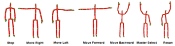
Figure 1: The gestures that are used for interaction with the robot
The Kinect sensor provides only the dimensions of the human’s joints, without describing the gestures. Thus, to build the gesture recognition system, the “y” values for the right & left elbows, the right & left wrists and the “y, z” values of the neck joints were extracted. Furthermore, machine learning (SVM) and artificial intelligence (BPNN) models were trained to define the gestures. To train the models, a training set of 448 samples is constructed, and the k-fold cross validation algorithm is used to train the models. Additionally, it is worthy to mention that the HRI system took into consideration that in real environments, the robot and the human might not be located face-to-face. Thus, the training set is extracted with different deviation angles between [-40°, 40°].
3. Cooperative Collision Avoidance
In previous collision avoidance systems, the robot will search for the closest collision-free path to the goal location, without taking into consideration the motion direction of the human. Since the human will also try to avoid the robot, both participants will get disordered about the correct direction that each of them has to go. This situation can cause problems when the robot navigates in social areas which include several people leading to a collision when both the human and the robot decide to use the same collision-avoidance direction. To overcome this situation, a new method for the collision avoidance is proposed which is called Cooperative Collision Avoidance System based on Interaction (CCAI) since both the robot and the human will cooperate in generating the collision-free path via interaction. Fig. 2 shows the flow chart of the proposed system.
In the proposed collision avoidance system after identifying people in the path the robot will send a voice message “Robot in the path”, alarming the people that the robot is moving in the same area. The people can move away from the robot’s path, or be prepared for interaction. If the human remain in the path, the robot will stop keeping a certain distance from the people (2m), asking them for interaction by sending a voice message “Interact”. Then the following situations can occur.
– If a user raised the right arm activating the “master gesture”, the robot will execute the orders provided by the user.
– If no human interacted with the robot, it will plan a collision-free path autonomously, taking into consideration the goal location.
– If the human moved away from the path of the robot, it will complete its path to the goal without changing its direction.
– If there is no available path that the robot can go through, it will send an alarm message “no free path” to inform the people that they have to keep a free path for the robot so it can generate a new collision-free path.
Fig. 3 shows three human in front of the robot; non of them interacted with it. The robot will then implement the collision avoidance path by searching for the regions that the robot can pass through. Then, it will select the region that is closest to its original path obtained from the global navigation system [13]. Since the robot has two available regions (R1, R2), it will select the region R2 since it is the closest to the original orientation to the goal.
In contrary, when the user interacts with the robot, it will follow the orders provided by the master via gestures. The red colored person in fig. 4 activated the “master person”, and asked the robot to move to the left. The robot will then select the region R1 since there is no free space between the persons P1, P2, and the region R2 is not located to the right of the master person.
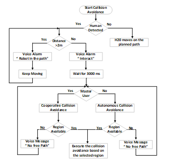
Figure 2: The flow chart of the collision avoidance system
To calculate the collision-free path, the robot has to search for all available regions that the robot can pass safely. Here the robot distinguishes between the terminal regions that are located to the right/left of the last person in the group, and the regions that exist between the people.
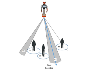
Figure 3: Selecting the CA region based on the goal location
In the first step, the robot detects the positions of the people, and calculates the relative distances between them. For the middle regions between the people, the robot calculates the width of the available distance between them:
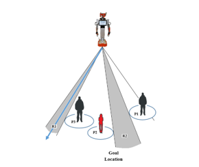
Figure 4. Selecting the CA path based on HRI
![]()
where represents the number of people detected by the Kinect sensor.
Furthermore, the robot estimates the minimum region width required for the robot to pass without collision:![]()
Where:
robot’s radius.
the distance between the shoulder and the neck of the
user obtained from Kinect sensor.
the safety distance around the robot.
In the next step, the robot checks the possibility of generating the avoidance path to the right and left of the most right/left people in the group. This calculation is done by considering the maximum detection angle of the sensor (70°), so the robot will compare the width of the region between the terminal person and the last point that the sensor can detect for the given depth, as it could be found in fig. 5, which shows the calculation of the region for the right-terminal person.
The following equations are used to get the width of the right-terminal region: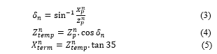
where
The distance of the person from the robot
The last point that the Kinect sensor can detect for the given depth
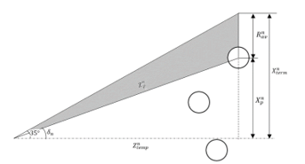
Figure 5. Calculation of available terminal region
The available region is given as: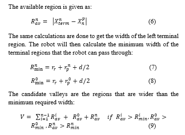
If , the robot couldn’t find a free walking area between the group of people, and it will send the voice message “no free path” to alarm the people to move and keep enough area for the robot to pass as it could be found in fig. 2.
If , the robot will select the valley depending on whether the master user asked the robot to go to a certain direction, or in case that no people interacted it will select the valley that is closest to its path. To calculate the collision-free path for the selected valley, the robot distinguishes between the terminal valley and the intermediate valley. Fig. 6 shows the calculation of the collision avoidance path for an intermediate valley using the following equations: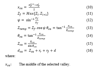
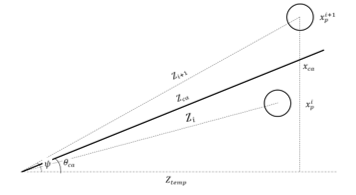
Figure 6. Calculating the collision-free path
The distance of the farthermost person from the robot in the selected region.
The robot’s orientation toward the valley.
The angle between the robot’s horizontal axis and the farthermost person in the selected region.
The horizontal distance between the robot and farthermost person.
The distance between the robot and middle of the Region.
The travelled distance to pass the people.
For the terminal valleys, the robot uses the following equations for the most right person: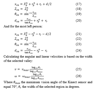
4. Experimental Results
The experiments have been implemented to check the performance of the HRI and the collision avoidance systems.
4.1 The experiments for the human-robot interaction
The experiments over the HRI were implemented on two steps. The first step, the experiments were applied to compare the performance of the SVM and BPNN and find out the best model that could fit the HRI system. After finding out the optimal model that can classify the training data, the HRI is tested for different gestures and different people to find the success rate of the implemented HRI system.
The goal of using the L_SVM and BPNN is to find the optimal model that could be used to recognize the gestures of different people with different heights and deviations from the Kinect level. To do so, a training set is implemented to train the models. Each training vector is composed of the “y” values of the right and left elbows, the “y” values of the right and left wrists, and the “y, z” values for the neck joint. The training data is collected from four people with different heights [152-187] cm. Each person is asked to do 112 gestures with distances [1.7, 4] m from the Kinect, with deviation angle [-40, 40]. Thus the total training set is 448. The L_SVM is trained for different penalty values, while the BPNN is trained for different number of hidden neurons.
To implement the training, the K-fold cross validation model is used with k=8.
4.1.1 Training the L_SVM model
The L_SVM is trained to find out the best penalty value that provides minimum error over the test set. The model is trained for penalty values . Table I shows the training results.
Table I. The training results of L_SVM model
| C | Total Error | Average Error | Success Rate (%) | Train time (ms) | Test Time (ms) | No. Support Vectors |
| 379 | 47.3 | 15.53 | [103, 112] | <1 | 21 | |
| 0.0183 | 335 | 44.3 | 20.9 | 102 | <1 | 21 |
| 0.0497 | 156 | 19.5 | 65.17 | 88 | <1 | 21 |
| 0.135 | 33 | 4.12 | 92.64 | 71 | <1 | 21 |
| 0.367 | 8 | 1 | 98.2 | 68 | <1 | 21 |
| 1, 2.718 | 9 | 1.125 | 97.99 | 49.56 | <1 | 21 |
| 7.389 | 8 | 1 | 98.2 | 45 | <1 | 21 |
| 16 | 2 | 96.4 | [41,53] | <1 | 21 |
From table I it can be seen, that the best penalty value that shows minimum error is at c=7.389 with 8 misclassified training samples for the 8 folds.
4.1.2 Training the BPNN model
|
Table II. The training results of BPNN model
|
The BPNN model is trained to find the best number of hidden neurons. The learning rate is set to . The model has five input neurons, three output neurons, while it is trained and tested to find the best number of hidden neurons with the range [3, 15]. Table II shows the experimental results for training the BPNN.
From table II, it could be concluded that despite of the number of hidden neurons, the model could correctly classify the whole test data successfully with no errors. Furthermore, in comparison with table I, it could be found that despite of the number of hidden neurons, the BPNN outperforms the implemented SVM model. Thus, the BPNN model is selected in the HRI system with a number of hidden neurons equal to 6.
4.1.3 Test the HRI system
After selecting the optimal model for the HRI system, further experiments have been implemented in real work conditions to check the performance of the HRI. To do so, five people with different heights and physical shapes were asked to do tests. Each person is asked to implement 18 gestures with different deviation angles [-40°, 40°]. Table III shows the experimental results for the HRI system.
Out of 90 experiments, two gestures were misclassified. These misclassifications occur due to false measurements for the joints’ locations by the Kinect sensor. Furthermore, state transition means the Kinect couldn’t detect the person that is located in front of it, and it required from him to move or shake their bodies to be detected from the sensor.
4.2 The experiments for the collision avoidance system
As mentioned in chapter 3, the robot uses the equations (25), and (26) to adjust its velocity based on the width of the selected region. Fig. 7 shows simulation for the velocity controller for different maximum linear and angular velocities taking into consideration that the maximum angular view for the sensor is 70°. Furthermore, to check the validity of the implemented system, several experiments were implemented for each function. H20 humanoid robot from DrRobot Company is used in the experiments.
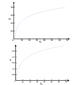
Figure 7: The simulation result for the velocity controller
4.2.1 Tests for the move forward/backward
The experiments for the move forward/backward gesture were implemented for different velocities . Two experiments were implemented for each velocity, one for each function. The experiments show that the robot could detect people, interact with the master and execute the orders based on the raised function. Fig 7. Shows an example of the cooperative collision avoidance in which the master asked the robot to move forward, and then he asked it to move to the right.
4.2.1 Tests for the move right/left
Fig 7. shows an example of the “move right” function after using the “move forward” gesture. To test the move right/left functions, 6 experiments were implemented. Table IV summarizes these experiments. represent the maximum linear and angular velocities that the robot uses in case that no obstacles in its path. Region candidates represent the possible steering angles that the robot can use to pass the detected regions. Heading angle represents the steering angle that the robot uses after selecting the region that the robot will go through it. (d) represents the distance that the robot will travel to pass the region. is the width of selected region. v, ω are the linear and angular velocities for the robot obtained from the velocity controller. Time represents the time that the robot needs to pass the people.
As it could be found, the robot will detect the whole navigable regions that are located at the right or left of the master person, depending on the direction that he/she ordered the robot to move. Then, it will calculate the steering angle and the distance that it has to move to pass the region. The robot will also consider the width of the selected region to calculate the linear and angular velocities.
4.2.2 Tests for the autonomous collision avoidance
As discussed before, in case of no human interaction the robot will generate the collision avoidance autonomously without any interaction. To test the function, additional six experiments were implemented to check the performance of the autonomous collision avoidance system. Table IV shows the experimental results for the system. Waypoint represents the original heading angle that the robot had to move if there are no people in the path.
The robot could successfully define the navigable regions, and select the region that is closest to its original path, by comparing the regions’ angles with the angle of the waypoint. Furthermore, it could be seen that the robot could successfully define the steering angle and the distance that it has to move to pass the region. Furthermore, the velocity controller will adjust the robot’s linear and angular velocities based on the width of the selected region.
4.3 Discussion and comparison with other systems
As it could be found in the experiments over the HRI system, the system is able to classify the whole gestures with a success rate 100%. Furthermore, the implemented system is able to detect and define the gestures even when the user is deviated with [-40°, 40°] from the straight line between the user and the robot. Other systems which are based on analyzing the geometrical displacements of the joints as in [14] and [15] will fail in such situations.
Although many collision avoidance systems proved a good performance in avoiding dynamic and static obstacles, all of these systems considered the humans as dynamic obstacles. This is a short come if we consider that in cluttered social environments, robots will navigate between many people who will share the location, and this could lead for both of them to get confused due to the lack of the interaction between them. Furthermore, the previous collision avoidance systems didn’t solve the bottleneck problem which could occur in narrow corridors and rooms, so the robot can’t generate collision avoidance paths due to the lack of space. Additionally, it is possible in certain situations that the human needs to interrupt the motion of the robot, and control it when needed.
The implemented system solved the bottleneck problem, by using the move forward/backward gestures. Thus, the master can lead the robot to another area which is wide enough to avoid each other. Furthermore, when there are several people in the path of the robot, a person can raise the “master select” gesture, and provide the robot the direction that it has to move, so the other group of people can go to another direction, and no motion conflict will occur. Besides to the interactive collision-avoidance features, the system is also able to generate the collision-avoidance path autonomously in similar concepts that other collision avoidance systems follow.
Future work will focus on detecting the static obstacles and integrate it to the implemented collision avoidance system, so the robot can avoid both the static, dynamic and human obstacles.
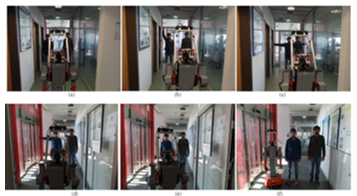
Figure 8: The cooperative collision avoidance, (a) the robot meets people in narrow path and ask them to interact, (b) the user raises his right arm to inform the robot that he will be the master, (c) the master person orders the robot to move forward, (d) the robot moves forward till it reach to a wide area and the user asks the robot to implement the collision avoidance to the right, (e, f) the robot adjusts its motion and moves to the free region to the right of the master
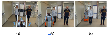
Figure 9: the autonomous collision avoidance, (a) the robot detects two people in the path and defines three navigable regions, (b) since no people interacted with the robot, it will select the region that is closest to its original path, (c) the robot calculates the path, pass the people and keep moving to the goal location.
|
Table IV: The experimental results for the move right/left functions
Table V: The experimental results for the autonomous collision avoidance function
|
Conflict of Interest
The authors declare no conflict of interest.
Acknowledgment
The study is funded by the Federal Ministry of Education and Research (FKZ: 03Z1KN11, 03A1KI1) and the German Academic Exchange Service (Ph.D. stipend M. Ghandour). The authors would also like to thank the Canadian DrRobot Company for the technical support for the H20 mobile robots in this study.
- V. Lumelsky and A. Stepanov, “Dynamic path planning for a mobile automaton with limited information on the environment,” IEEE Trans. Autom. Control, vol. 31, no. 11, pp. 1058–1063, Nov. 1986.
- D. Fox, W. Burgard, and S. Thrun, “The dynamic window approach to collision avoidance,” IEEE Robot. Autom. Mag., vol. 4, no. 1, pp. 23–33, Mar. 1997.
- O. Khatib, “Real-time obstacle avoidance for manipulators and mobile robots,” in 1985 IEEE International Conference on Robotics and Automation. Proceedings, 1985, vol. 2, pp. 500–505.
- J. Borenstein and Y. Koren, “The vector field histogram-fast obstacle avoidance for mobile robots,” IEEE Trans. Robot. Autom., vol. 7, no. 3, pp. 278–288, Jun. 1991.
- J. Minguez and L. Montano, “Nearness diagram (ND) navigation: collision avoidance in troublesome scenarios,” IEEE Trans. Robot. Autom., vol. 20, no. 1, pp. 45–59, Feb. 2004.
- C. A. Cifuentes, A. Frizera, R. Carelli, and T. Bastos, “Human–robot interaction based on wearable IMU sensor and laser range finder,” Robot. Auton. Syst., vol. 62, no. 10, pp. 1425–1439, Oct. 2014.
- S. Boubou and E. Suzuki, “Classifying actions based on histogram of oriented velocity vectors,” J. Intell. Inf. Syst., vol. 44, no. 1, pp. 49–65, Jul. 2014.
- I.-J. Ding and J.-Y. Shi, “Kinect microphone array-based speech and speaker recognition for the exhibition control of humanoid robots,” Comput. Electr. Eng.
- E. Hortal et al., “SVM-based Brain–Machine Interface for controlling a robot arm through four mental tasks,” Neurocomputing, vol. 151, Part 1, pp. 116–121, Mar. 2015.
- C. C. Tsai, Y. Z. Chen, and C. W. Liao, “Interactive emotion recognition using Support Vector Machine for human-robot interaction,” in IEEE International Conference on Systems, Man and Cybernetics, 2009. SMC 2009, 2009, pp. 407–412.
- M. Ghandour, H. Liu, N. Stoll, and K. Thurow, “A hybrid collision avoidance system for indoor mobile robots based on human-robot interaction,” in 2016 17th International Conference on Mechatronics – Mechatronika (ME), 2016, pp. 1–7.
- M. Ghandour, H. Liu, N. Stoll, and K. Thurow, “Interactive collision avoidance system for indoor mobile robots based on human-robot interaction,” in 2016 9th International Conference on Human System Interactions (HSI), 2016, pp. 209–215.
- A. A. Abdulla, H. Liu, N. Stoll, and K. Thurow, “Multi-floor navigation method for mobile robot transportation based on StarGazer sensors in life science automation,” in Instrumentation and Measurement Technology Conference (I2MTC), 2015 IEEE International, 2015, pp. 428–433.
- G. Canal, S. Escalera, and C. Angulo, “A Real-time Human-Robot Interaction system based on gestures for assistive scenarios,” Comput. Vis. Image Underst.
- N. Yang et al., “A study of the human-robot synchronous control system based on skeletal tracking technology,” in 2013 IEEE International Conference on Robotics and Biomimetics (ROBIO), 2013, pp. 2191–2196.