Impact of PSS and SVC on the Power System Transient Stability
Impact of PSS and SVC on the Power System Transient Stability
Volume 2, Issue 3, Page No 562-568, 2017
Author’s Name: Mohammed Omar Benaissaa), Samir Hadjeri, Sid Ahmed Zidi
View Affiliations
Laboratory of Intelligent Control and Electrical Power System, University Djillali Liabes, Sidi Bel Abbes 22000, Algeria
a)Author to whom correspondence should be addressed. E-mail: omarioriquelme10@yahoo.fr
Adv. Sci. Technol. Eng. Syst. J. 2(3), 562-568 (2017); ![]() DOI: 10.25046/aj020372
DOI: 10.25046/aj020372
Keywords: AVR, Power System, PSS, SVC, Short Circuit, Transient Stability

Export Citations
The Static Var Compensator (SVC) is used to improve the stability of the power system because of its role in injecting or absorbing the reactive power in the electrical transmission lines. The Power System Stabilizer (PSS) is also a control device which ensures maximum power transfer and thus the stability of the power system enhancement. The PSS has been widely used to damp electromechanical oscillations occur in power systems. If no adequate damping is available, the oscillations will increase leading to instability. The present work is an original contribution to the problem of transient stability in the electrical power system, the authors have made some efforts to illustrate the flexibility and the importance of inserting the SVC alone or with the PSS the fact that maintain the characteristics of the system within acceptable limits in a very short time. The results show that the system has been developed successfully in terms of transient stability in a bi-machine transmission system only with the presence of PSS when a single-phase fault has been occurred, while the presence of SVC is more than essential when a three-phase fault is occurred.
Received: 27 March 2017, Accepted: 01 May 2017, Published Online: 01 June 2017
1. Introduction
Today’s world is continuously growing so that generation distribution and transmission of power are also simultaneously required to increase in same manner to fulfill the requirement. Power system stability may be broadly defined as that property of a power system that enables it to remain in a state of operating equilibrium under normal operating condition and to regain an acceptable state of equilibrium after being subjected to a disturbance [1].
Stability of this system needs to be maintained even when subjected to large low-probability disturbances so that the electricity can be supplied to consumers with high reliability. Certain system disturbances may cause loss of synchronism between a generator and the rest of the utility system, or between interconnected power systems of neighboring utilities. Various control methods and controllers have been developed over time that has been used for this purpose.
Recently, there has been a surge of interest in the development and use of FACTS controllers in power transmission systems. These controllers utilize power electronics devices to provide more flexibility to AC power systems. The most popular type of FACTS devices in terms of application is the SVC [2]. This device is well known to improve power system properties such as steady state stability limits, voltage regulation, and damp power system oscillations [3]. The SVC is an electronic generator that dynamically controls the flow of power through a variable reactive admittance to the transmission network, also the SVC regulates voltage at its terminals by controlling the amount of reactive power injected into or absorbed from the power system [4]. When system voltage is low the SVC generates reactive power (SVC capacitive). When system voltage is high, it absorbs reactive power (SVC inductive) [5].
It is known that the power-system stabilizers PSS for generators and the supplementary controllers for flexible ac transmission system (FACT) devices are efficient tools for improving the stability of power systems through damping of low-frequency modes [6], where the frequency of these modes ranges from 0.2 to 2.5 Hz [7]. Power System Stabilizer (PSS) devices are responsible for providing a damping torque component to generators for reducing fluctuations in the system caused by small perturbations [8].
Generally, it is important to recognize that machine parameters change with loading make the machine behavior quite different at different operating conditions. Since these parameters change in a rather complex manner, a set of stabilizer parameters, which stabilizes the system under a certain operating condition, may no longer yield satisfactory results when there is a drastic change in power system, stabilizers PSS should provide some degree of robustness to the variations in system parameters, loading conditions, and configurations [10, 11]. The basic structure of PSS is operating under typical control generator while the basic structure of SVC is operating under typical bus voltage control [13]. In some cases, when the use of PSS cannot provide sufficient damping for inter-area power swing (0.1-0.7Hz), SVC damping controller is an alternative effective solution. The SVC supplemented with damping controller and PSS on synchronous generators are applied to increase the probability of stability [9].
This paper is an extension of work originally reported in Proceedings of the International Conference on modeling, identification and control [12]. Firstly we start with an introduction containing an overview of the system under examination, in section two we have given a detailed description of the proposed system, section three is divided into two parties the first one shows the results obtained and discuss the impact of PSS when a single-phase fault is occurred whereas the second one discuss the impact of the SVC when a three-phase fault occurred, finally we have drawn an overall conclusion which reveals the most important point to consider from the current work.
2. System Description
The proposed power system works under abnormal system conditions and has the following characteristics see Figure 1.
- Two synchronous generators
- Two power transformers of 13.8 kV / 500 kV.
- Three bus bars.
- A transmission line of 500 kV and 700 km.
- Two PSS and two AVR (Automatic Voltage Regulator).
- The SVC characteristics: 200 Mvar.
- A purely resistive load of 5000 MW.
Note that the load center is modeled by (5000 MW) resistive load which is fed by the remote of (1000 MVA-plant M1), and a local generation of (5000 MVA-plant M2). A load flow has been performed on this system for G1 and G2 with generating rate of (950 MW and 4046 MW) respectively while the line carries (944 MW) which is closed to its surge impedance loading (SIL = 977 MW). The shunt compensated used in this research is with rate of (200 Mvar) to maintain system stability after faults [14].
The SVC does not have a power oscillation damping (POD) unit. G1 and G2 are equipped with a Hydraulic Turbine and Governor (HTG), excitation system, and Power System Stabilizer (PSS). Two standard types of stabilizer models can be connected to the excitation system: Generic model using the acceleration power (Pa which is the difference between mechanical power (Pm) and electrical output power (Peo) and Multiband model which uses a speed deviation (dw) [14].
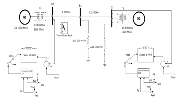
Figure 1. The Simplified Diagram of the Multi-Machine Power System with SVC and PSS
3. Problem Statement
3.1. PSS Modeling and Damping Controller Design
The operating function of a PSS is to produce a proper torque on the rotor of the machine involved in such a way that the phase lag between the exciter input and the machine electrical torque is compensated [15]. The block diagram of the ith PSS with excitation system is shown in Figure 2, where (ΔUi) is the deviation in speed from the synchronous speed which is the input signal. The output signal of the PSS is used as an additional input (ΔUi) to the Excitation System block [16]. The three basic blocks of a typical PSS model are: The first block is the stabilizer Gain block, which determines the amount of damping. The second is the Washout block, which serves as a high-pass filter. The last one is the phase compensation block, which provides the desired phase-lead characteristic to compensate for the phase lag between the AVR input and the generator electrical (air-gap) torque [17].
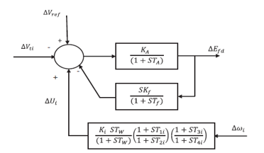
Figure 2. Block diagram of ith PSS with excitation system [16]
3.2. SVC modeling and damping controller design
A Static Var Compensator (SVC) is composed of a fixed capacitor in parallel with a thyristor controlled reactor (FC-TCR), this model consists of a harmonic voltage source in series with a variable source admittance [18]. The SVC adjusts the susceptance in each phase by controlling the conducting angles of the thyristor controlled reactor [19]. Also it can control the unbalanced loads more effectively and can enhance the transient stability of the system by inserting or absorbing instantaneous currents to or from the system [20].
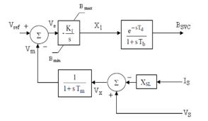
Figure 3. SVC Control Model
The equations describing the SVC controller are: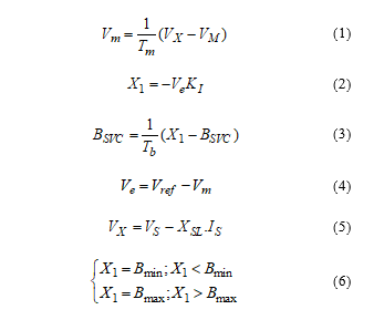
Where
Bmin: is the minimum susceptance
Bmax: is the maximum susceptance
BSVC: is the Static Var Compensator susceptance
KI: is the proportional gain
Tm: is the measuring time
Vm: is the measured voltage
VX: is the voltage at X position
Vref: is the reference voltage.
Xl: is the line reactance
XSL: is the slope.
4. Simulation Results and Discussion
This work illustrates modeling of a simple transmission system containing two hydraulic power plants. A Static Var Compensator (SVC) and Power System Stabilizers (PSS), In order to observe the impact of PSS and SVC on the power system stability a single-phase to ground fault and a three-phase fault have been applied on the first section of the line (L1) see Figure 1.
4.1. Single-Phase Fault – Impact of PSS – No SVC
In this part the SVC is set to operate in fixed susceptance mode with (Bref=0) this is equivalent to putting the SVC out of service. Also a single-phase to ground fault have been applied at t=0.1 s and eliminated at t=0.2 s.
- PSS out of service
Figure 4 shows the obtained graphs without the impact of the PSS, if a single-phase fault is applied, immediately the system tends to support the oscillations, then these oscillations increased more and more, so that the system loses its steady state.
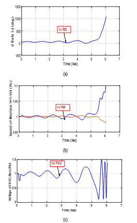
Figure 4. Impact of PSS for 1-phase fault (without PSS): (a) Rotor angle difference d_theta1_2 between the two machines, (b) Machine speeds of G1and G2, (c) Voltage at SVC-Bus.
- PSS Generic type in service
Figure 5 shows the impact of PSS Generic type, if a single-phase fault is applied, Figure 5(a) shows the Rotor angle difference d_theta1_2 between the two machines, it is found that the angle is approximately (50°) at the fault clearing time, Figure 5(b) shows that machine speeds (W1, W2) for G1 and G2 respectively converge to 1 Pu, so the machine speeds oscillate at the same time for low frequencies at 0.025Hz. Figure 5(c) shows that the voltage at SVC-bus is constant.
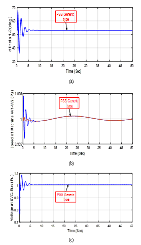
Figure 5. Impact of PSS for 1-phase fault (with PSS Generic type): (a) Rotor angle difference d_theta1_2 between the two machines, (b) Machine speeds of G1and G2, (c) Voltage at SVC-Bus.
- PSS Multi-Band type in service
Figure 6 shows the impact of PSS Multi-Band type, if a single-phase fault is applied, the same results shown above with PSS Generic type have been drawn, however the Multi-Band type can attenuate not only the frequencies of 0.8Hz but also 0.025Hz .
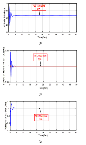
Figure 6. Impact of PSS for 1-phase fault (with PSS Multi-Band type): (a) Rotor angle difference d_theta1_2 between the two machines, (b) Machine speeds of G1and G2, (c) Voltage at SVC-Bus.
Now the results have been assembled in the same graph to allow comparison between a various cases (without PSS, with PSS Generic type and with PSS MB type.
The first trace of Figure 7 shows the rotor angle difference d_theta1_2 between the two machines. Power transfer is maximum when this angle reaches 90°, this signal is a good indication of system stability. If d_theta1_2 exceeds 90º for too long a period of time, the machines will lose synchronism and the system goes unstable.
The second trace of Figure 7 shows the speed oscillation of machine G1 notice that machine 1 speed increases during the fault because during that period its electrical power is lower than its mechanical power.
The third trace of Figure 7 shows the positive sequence voltage at the SVC bus, we notice that as soon as the fault has been applied the voltage grows to reach 1.08 then this peak is followed by oscillations.
In the blue waveforms we can clearly see that, if there is no PSS than system can’t be able to sustain stability and lose it synchronism (see Figure 7). In the red waveforms notice that when we use PSS Generic type system becomes stable but there is low frequency oscillation present (see Figure 7). In the magenta waveforms we notice that when we use PSS MB type system may be stable with no low frequency oscillation.
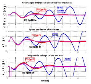
Figure 7. Impact of PSS for 1-phase fault (without SVC)
4.2. Three-Phase Fault – Impact of SVC
This part contains two tests, in the first one the SVC is set to operate in fixed susceptance mode with (Bref=0) this is equivalent to putting the SVC out of service. The second one, the SVC is set to operate in voltage regulator mode; however, the PSS Generic type has been maintained in service. Also a three-phase to ground fault have been applied at t=0.1 s and eliminated at t=0.2 s.
- SVC out of service
Figure 8 shows the obtained graphs with PSS Generic type in service and without the impact of the SVC (fixed susceptance mode Bref=0), if a three-phase fault is applied, immediately the system tends to support the oscillations, then these oscillations increased more and more, so that the system loses its steady state.
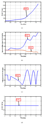
Figure 8. Impact of the SVC for 3-phase fault. (without SVC): (a) Rotor angle difference d_theta1_2 between the two machines, (b) Machine speeds of G1and G2, (c) Voltage at SVC-Bus, (d) Susceptance of SVC
- SVC in service
Figure 9 shows the impact of SVC (voltage regulation mode), if a three-phase fault is applied. Figure 9(a) shows the rotor angle difference d_theta1_2 between the two machines, it is found that the angle is approximately (70°) at the fault clearing time. Figure 9(b) shows that machine speeds (W1, W2) for G1 and G2 respectively converge to 1 Pu. Figure 9(c) shows that the voltage at SVC-bus is constant and equals to 1 Pu. Figure 9(d) shows that the SVC tends to support the voltage stability by injecting the reactive power into the transmission line whenever is needed (measured voltage differs from the reference voltage).
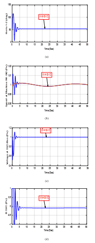
Figure 9. Impact of the SVC for 3-phase fault. (with SVC): (a) Rotor angle difference d_theta1_2 between the two machines, (b) Machine speeds of G1and G2, (c) Voltage at SVC-Bus, (d) Susceptance of SVC
Now, the results have been assembled in the same graph to allow comparison between the two tests (without SVC and with SVC).
Here we show that if there is three-phase transient fault than without SVC, both PSS are not able to maintain the stability. By looking at the red waveforms we should observe that the two machines quickly fall out of synchronism after fault clearing. In order not to pursue unnecessary simulation, the Simulink ‘Stop’ block is used to stop the simulation when the angle difference reaches 3*360degrees.
Now the SVC is set to operate in voltage regulation mode. The SVC will now try to support the voltage by injecting reactive power on the line when the voltage is lower than the reference voltage (1.009 pu). In steady state the SVC will therefore be ‘floating’ and waiting for voltage compensation when voltage departs from its reference set point.
The results of these studies show that the SVC has an excellent capability in damping power system oscillations and enhances greatly the dynamic stability of the power system. We also note that the stabilization time is minimal.
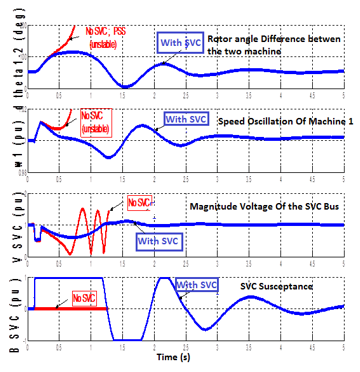
Figure 10. Impact of the SVC for 3-phase fault
5. Conclusion
From simulation results of the proposed model we can conclude:
- The proposed model is oscillatory and instable with absence effects of (PSS) and SVC.
- The selective of (PSS) are capable of proving sufficient damping to the steady state oscillation and transient stability voltages performance over a wide range of operating conditions and various types of disturbances of the system used in proposed model.
- If there is Single line to ground fault than the PSS able to sustain the stability, but using SVC the angle deviation is reduced.
- If there is three phase transient fault then without SVC both PSS are not able to maintain the stability.
- Compare working two types of (PSS), the multiband type oscillation is quickly damped than generic type.
- N.G. Hingorani, L. Gyugyi, Understanding FACTS: Concepts and Technology of Flexible AC Transmission Systems, IEEE Press, 2000.
- T. R. Hussein, “Using Power System Stabilizers (PSS) And Shunt Static Var Compensator (SVC) For Damping Oscillations In Electrical Power System” Journal of faculty MAAMOUN .
- S. Panda, N.P. Padhy, “Power system with PSS and FACTS controller modeling, simulation and simultaneous employing genetic algorithm,” International Journal of Electrical and Electronics Engineering, 9-18, 2007.
- J. Wang , C. Fu, Y. Zhang, “SVC control system based on instantaneous reactive power theory and fuzzy PID” IEEE Trans. Industrial Electronics, 55(4) , 1658-1665, 2008.
- L. Xu, “Coordinated control of SVC and PSS for transient stability enhancement of multi-machine power system” TELKOMNIKA, 11(2), 1054-1062, 2013.
- M. Nadarajah, C. A. Canizares, R. John, G. J. Rogers, “Comparison of PSS, SVC, and STATCOM Controllers for Damping Power System Oscillations” IEEE Trans. Power Syst., 18(2), 786-792, 2003.
- M. Khaleghi, M. M. Hossein Nezamabadi-pour, K. Y. Lee, “Pareto-optimical design of damping controllers using modified artificial immune algorithm” IEEE Trans. Power Syst., 41(2), 240-250, 2010.
- F. Milla, M. A. Duarte-Mermoud, “Predictive optimized adaptive PSS in a single machine infinite bus” ISA Transactions, 63, 315-327, 2016.
- X. Y. Bian, Y. Geng, K. L. Lo, Y. Fu, Q. B. Zhou, “Coordination of PSSs and SVC damping controller to improve probabilistic small-signal stability of power system with wind farm integration” IEEE Trans. Power Syst., 31(3), 2371-2382, 2016.
- M.A. Abido, Y.L. Abdel-Magid, “Coordinated design of a PSS and an SVC- based controller to enhance power system stability” International journal of Electrical Power and Energy Systems, 25(9), 695-704, 2003.
- A. Ali, “Development of system with transitory steadiness of a bi-machine transmission system with power system stabilizers and static Var compensator” International Journal of Engineering Research and Applications, 3(3), 1121-1125, 2013.
- B. M. Omar, H. Samir, Z. S. Ahmed, “Impact of PSS and SVC on The Power System Transient Stability” in 8th International Conference on Modelling, Identification and Control, Medea and Algiers Algeria, 2016.
- K. Alok, D. Surya Bhushan, “Enhancement of transient stability in transmission line using SVC facts controller” International Journal of Recent Technology and Engineering, 2(2), 2013.
- S. Gilbert, Transient Stability of a Two-Machine Transmission System with Power System Stabilizers (PSS) and Static Var Compensator (SVC), SimPowerSystems (Guid’s), MathWork, MATLAB Simulink version 7.2.0, 2010.
- S.M. Abd-Elazim, E.S. Ali, “Coordinated design of PSSs and SVC via bacteria foraging optimization algorithm in a multi-machine power system” Electrical Power and Energy System , 41 (1), 44-53, 2012.
- N. Anil kumar, K. Ramesh, “Transient stability improvement using SVC and PSS” International Research Journal of Engineering and Technology, 03(7), 1305-1311, 2016.
- K. Khalid, H. Saleh, E. Ercelebi, “Transient stability improvement in multi-machine system using power system stabilizer (PSS) and static Var compensator (SVC)” International Journal of Electrical, Computer, Energetic, Electronic and Communication Engineering, 09(12), 1362-1375, 2015.
- L. J. Bohmann, R. H. Lasseter, “Equivalent circuit for frequency response of a static Var compensator” IEEE Trans. Power Syst, 1(4), 1986.
- A. Köse, E. Irmak, “Modeling and Simulation of a Static VAR Compensator Based on FC-TCR” in 5th international conference on Renewable Energy Research and Applications, Birmingham UK, 2016.
- M. A. Hossain Sadi, M. Hasan Ali, “Combined operation of SVC and optimal reclosing of circuit breakers for power system transient stability enhancement” Electric Power Systems Research, 106, 241-248, 2014.