Multi-Domain Virtual Network Embedding with Coordinated Link Mapping
Multi-Domain Virtual Network Embedding with Coordinated Link Mapping
Volume 2, Issue 3, Page No 545-552, 2017
Author’s Name: Shuopeng Lia), Mohand Yazid Saidi, Ken Chen
View Affiliations
L2TI, Institut Galiléee Université Paris 13 Sorbonne Paris Cité Villetaneuse, France
a)Author to whom correspondence should be addressed. E-mail: li.shuopeng@univ-paris13.fr
Adv. Sci. Technol. Eng. Syst. J. 2(3), 545-552 (2017); ![]() DOI: 10.25046/aj020370
DOI: 10.25046/aj020370
Keywords: Network Virtualization, Virtual network embedding, Multi-domain

Export Citations
Network Virtualization, which allows the co-existence of various logical networks on shared physical infrastructure, has become popular in recent years. The optimal mapping of virtual resource to physical resource is a major issue in network virtualization. This problem, called virtual network embedding (VNE), has been well explored in the context of one physical domain, which is in practice operated by a single infrastructure provider (InP). However, the needs of virtual network (VN) is rapidly growing, and quite a number of VNs have to be established across multi-domain. For multi-domain VNE, infrastructure providers can no longer just solve their own single domain VNE problem, but have to cooperate to build the whole VN. Therefore, new challenge arises for the multi-domain VNE, compared to traditional single domain VNE. The existing investigations on this problem mainly focus on decomposing a VN to sub VN for each domain, but little attention has been paid to the joint relation between intra-domain and inter-domain (peering) links. In this paper, we propose a multi-domain link mapping method which combines the intra and peering link mapping so as to optimize the overall resource utilization. Our approach is easy to be deployed since it is based on current Internet architecture. Evaluation shows that our approach brings improvements related to existing methods.
Received: 03 April 2017, Accepted: 12 May 2017, Published Online: 01 June 2017
1 Introduction
Network virtualization [1] is regarded as a solution to overcome some weakness of traditional network architecture. It makes easy to support various separated logical networks running over shared physical network. In virtualized network architecture, the service provider (SP) creates and manages virtual networks (VN) for end users,while infrastructure provider (InP) deploys the substrate network (SN) equipment and offers the necessary physical resources. An important step of network virtualization is to establish VNs above SNs. This is referred as virtual network embedding (VNE). The VNE problem aims to find a mapping from the VN to SN in a way that objectives (e.g. cost) are optimized and constraints (e.g. bandwidth) are satisfied. Large networks in current Internet architecture are organized by autonomous system (AS). An AS is one or several physical networks controlled by a single authority. In this article, we use the vocabulary of “domain” to denote the whole substrate network under the control of a single InP.
Network virtualization [1] is regarded as a solution to overcome some weakness of traditional network architecture. It makes easy to support various separated logical networks running over shared physical network. In virtualized network architecture, the service provider (SP) creates and manages virtual networks (VN) for end users,while infrastructure provider (InP) deploys the substrate network (SN) equipment and offers the necessary physical resources.
An important step of network virtualization is to establish VNs above SNs. This is referred as virtual network embedding (VNE). The VNE problem aims to find a mapping from the VN to SN in a way that objectives (e.g. cost) are optimized and constraints (e.g. bandwidth) are satisfied.
Large networks in current Internet architecture are organized by autonomous system (AS). An AS is one or several physical networks controlled by a single authority. In this article, we use the vocabulary of As VNs are getting more and more deployed, VNs in multi-domain will be more and more considered by potential VN users. Establishment of multi-domain VN is more difficult than the one on single domain for at least two reasons:
- First, a single domain VNE problem is mainlysolved by linear programming (LP). If we had a complete vision of all the domains, a multidomain VNE could be considered as a single domain VNE with a very large domain, so computationally harder to solve.
- More importantly, for various reasons (techni-cal, commercial, etc.), the acquisition of full information in multi-domain is costly and often not possible. Only limited information is exchanged between InPs via protocols like BGP, so single domain approach cannot be re-used.
To address these challenges, multi-domain VNE
frameworks are developed. Usually, there is a VN decomposition step followed by local sub VN mapping in each InP. Some authors introduced a brokerlike additional actor, termed Virtual Network Provider (VNP) [2], between SP and InPs. The role of this VNP consists in assembling multi-domain information, decomposing VN and achieving the multi-domain VNE.
Existing solutions mainly focused on the decomposition of a multi-domain VN to each domain. One of the shortcomings in these frameworks is the lack of efficient link mapping method especially for the peering links which interconnect two domains.
In this paper, we propose an efficient framework of link mapping in multi-domain virtual network embedding context, which jointly consider the mapping of intra and peering links. In our approach, the peering links are mapped simultaneously along with intra domain links. Our approach is based on information usually disseminated by classical routing protocol (like BGP). Our simulation results prove that this solution results in better utilization of substrate resources.
The rest of this paper is organized as follows. Section 2 provides an overview of the related work. Section 3 presents our network model. Section 4 presents our multi-domain VNE solution. The evaluation results are shown in section 5. Section 6 concludes this paper.
2 Related Work
2.1 Single domain VNE
The problem of single domain VNE is NP-hard [3] [4]. A basic off-line approach is proposed in [5], which performs the embedding in 2 stages (node then link mapping). The Multi Commodity Flow (MCF) is introduced in [6] to embed the virtual links The method in [7] takes into account the virtual links in node mapping stage. It privileges such node mapping that reduce the length of substrate link path.
Since 2-stage VNE solutions are lack of cooperation, some solutions mapping nodes and links in the same stage have been proposed. An approach based on subgraph isomorphism detection is presented in [8]. An other model in [9] applies the Markov Random Walk to rank nodes and then embeds links and nodes by using back-tracking strategy based on breadth-first search. In order to meet the change of requirements over time, dynamic VNE is proposed in [10] .
2.2 Multi-domain information disclosure
Because of politic and efficiency reasons, InPs can’t disclose their complete information to others, so it is critical to make clear the information disclosure policy.
The proxy VNP could get peering links location and resource information but intra-domain links cannot be assumed to be available to VNP [11].
In [12], three types of resource information in each domain are provided to VNP:
- Node: its location, available capacity and unit price.
- Peering link: its vertices, available capacity and unit price.
- Intra-domain link: a length-based price for connecting any two nodes in its domain.
Based on the information disclosure policy above, we will describe our network model in the next section.
2.3 Multi-domain VNE
Multi-domain VNE framework can be decomposed into three major components [13]:
- partitioning the VN request into each InP via multi-domain node mapping method,
- establishing inter-domain connection (peering links) between InPs using inter-domain paths,
- embedding each sub VN request in each InP using intra-domain algorithm.
Based on multi-domain information model introduced in previous section, some centralized multi-domain VNE solutions are proposed in
[14][11][12][15].
Many of them mainly focus on the first component. In [14], the authors introduce the cost of mapping a virtual node to a domain and the cost of mapping a link between two substrate nodes. Their node mapping algorithm optimizes the total embedding cost. The approach in [12] adopts the node mapping method [7] on a full-mesh topology which complies with partial information disclosure policy.
The second component is not very well explored compared to the first component. Existing solutions use simple policies to establish peering links. In [14], each peering link is considered as a single VPN (Virtual Private Network) connection. In [12], the flow of peering links is unsplittable between two domains, while the intra-domain sub virtual links are splittable. The peering link path is determined by Dijkstra’s algorithm on VNP layer. Since VNP layer topology is not modified over time because of cost efficiency, Dijkstra’s algorithm based peering links have always the same path. This phenomenon will result in difficulty of later intra-domain mapping. In [11], a virtual node is first mapped to substrate peering node to determine the peering link and the InP it belongs to. This approach is suitable for traffic matrix based VN [16] but not topology based VN.
Since establishing peering links is a part of link mapping, the chosen peering nodes will probably influence the intra-domain paths. We believe that there exist some inter-dependencies between the 2nd and 3rd components. To this end, we propose a framework which maps peering links jointly with intra-domain links in each InP.
3 Network Model
We adopt the usual substrate and virtual network model [7]. In addition, we describe VNP layer information based on existing multi-domain information model.
3.1 Substrate Network
A domain InPi is modelled as an undirected graph GiS(NiS,LSi ), where NiS is the set of substrate nodes in domain i, LSi is the set of internal substrate links. Each substrate node nsi ∈ NiS is associated with a CPU capacity cpu(nsi) and a geographic location loc(nsi). Each substrate link lis ∈ LSi is associated with a bandwidth capacity bw(lis).
Assuming that the substrate network covers K domains, there are some peering nodes (border nodes) which have peering links with other domains. The peering nodes set is denoted by NiSP (NiSP ⊂ NiS). The peering links between InPi (i.e. GiS) and InPj (i.e. GjS) is denoted by LSij. We denote by PiS = ∪Kj=1LSij the set of all of the peering links of InPi, and by P S with P S = SKi=1PiS = S(i,j)∈(1…K)2 LijS the set of all of the peering links. The complete substrate network GS(NS,LS) is thus obtained as follows: NS = SKi=1NiS, LS = (SKi=1LSi )SP S.
3.2 Virtual network
The virtual network is also modelled as an undirected graph GV (NV ,LV ), where NV is the set of virtual nodes and LV is the set of virtual links. Each virtual node nv ∈ NV is associated with a CPU capacity demand cpu(nv), a geographic location loc(nv) and a distance constraint dis(nv) specifying how far a virtual node nv can be placed from its loc(nv). Each lv ∈ LV is associated with a bandwidth demand bw(lv). In addition, each virtual network GV has a lifetime t(GV ).
3.3 VNP layer model
VNP collects information provided by InPs. We assume that InPs provide exact information about their nodes, as well as the peering links. On the contrary, there is no exact information about the internal organisation of a domain. Similar to the existing solution [12], we assume that this information is given by InP for each couple of <node, peering node>, as if there was a pseudo direct link between these two nodes. Denote the set of these links by LPi = {lmn / m ∈ NiS,n ∈
NiSP }, InPi provides to VNP the set of linking cost CiP defined by
CiP = {C(lmn) / m ∈ NiS,n ∈ NiSP }
where C(lmn) represents a cost (distance, bandwidth, etc.) characterizing the link lmn. This kind of information is actually what a routing protocol (BGP) reports to other AS.
Thus, the SN of an InPi is perceived by VNP as a graph GiP = (NiS,LPi ). In this way, the whole substrate network that VNP perceives, referred as GP , is defined as follows:
GP = ([GiP )[P S
i
i.e. the perceived vision for each domain and the exact vision of the inter-domain connections. With GP , VNP can establish a kind of complete topology covering all the domains for achieving VN decomposition and link mapping.
4 Our proposition
To solve VNE in the context of multi-domain, we propose a novel algorithm that maps jointly intra and peering links.
We propose to handle each VN request with a 2step process
- At the first step, VNP performs the node decomposition optimizing the node embedding.
- Subsequently, VNP performs a series of iterative downsizing VNE sub-solution, each of them optimizes both the intra and peering link mapping related to a domain.
The link mapping is determined, at each iteration, by the acting InP (called mapper). VNP is in charge of providing necessary information to the mapper. The generic work-flow of our algorithm is given by figure 1. The details are explained as below.
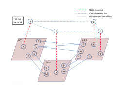
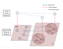
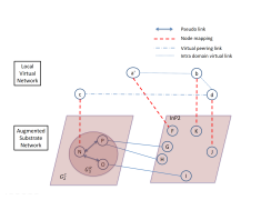
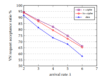
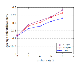
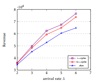
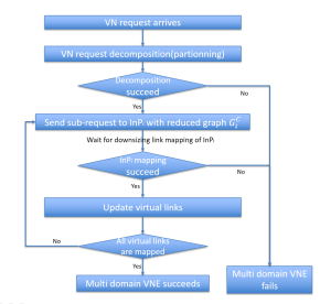 Figure 1: VNP workflow to embed a VN
4.1 Decomposition
Firstly, VNP decomposes the VN request with objective of minimizing the node mapping cost. In this stage, VNP associates each virtual node with a candidate set of substrate nodes that meet its loc(nv). VNP is free to use any multi-domain VN partitioning
Figure 3: downsizing link mapping
Figure 4: downsizing link mapping
Figure 2: VN decomposition
by InP1 by InP2
method (e.g. [14][12]). At the end of this stage, virtual nodes are embedded to different domains.
An example of VN decomposition is shown in figure 2. Three InPs are shown with their substrate nodes from A to P. They are connected via 2 or 3 peering links. Intra substrate links are not drawn. We suppose that a VN {a,b,c,d} arrives. The VN decomposition step tells us that a, b, c and d are mapped to substrate nodes A, K, N and J, respectively. {a − b,a − c,c − d} are virtual links which interconnect two different domains, while {b −d} locates in only one domain.
4.2 An iterative downsizing VNE approach
Here we give a detailed presentation of the kernel of our proposal, which is formally given in algorithm 1.
4.2.1 Rationale
After VN decompostition step, since there is no domain who knows the complete information of any other one, embedding the virtual links which interconnect two different domains becomes an issue.
We notice that, VNP can build, for each InPi, a reduced vision (denoted by GiR) from GiP . This vision contains all the peering links/nodes, as well as the substrate nodes on which a virtual node is embedded. Formally, GiR = (NiR,LRi ) where
NiR = NiSP [{nSi ∈ NiS / ∃nv ∈ NV ,M(nv) = nSi }
i.e., NiR is the union of all the substrate nodes supporting virtual nodes on domain i and all of its peering nodes. In a similar way, we define LRi as follows;
LRi = {lmn ∈ LPi /n ∈ NiR,m ∈ NiSP }
i.e., LRi is the subset of LPi between NiR and NiSP containing only the links interconnecting a peering node and a node supporting a virtual node.
In order to achieve an efficient and pragmatic operation mode, we prefer that VNP plays its role of coordinator: It is VNP who decides which of the InP should have the privilege to map its peering links with others. It is also VNP who provides to the chosen InP (that we refer as mapper) the topology of the rest of the network according to its perception. In other words, the chosen InP (the mapper) extends its view to the rest of the network, by using the vision provided by VNP, the only one who has a kind of comprehensive view on all domains. In this way, the mapper obtains an augmented graph on which it will perform link mapping, including both its intra and peering links.
This process continues, domain after domain, until all of the virtual links are set. The selection criterion is the link utilization, the InP has most stringent link utilisation will be the first to map its peering links. The reason lies in that high link utilization denotes more constraints in the choice of path.
4.2.2 Building of the augmented graph
Let InPi be the chosen mapper. Formally speaking, the vision of the other domains provided by VNP is GiC = Sj,i GjR, i.e. the reduced perceived vision of all the other domains. We only need to consider the case where all the domains are adjacent to the mapper. The case of a domain not adjacent to the mapper but to which the mapper has virtual links can be reduced to the adjacent case.
VNP communicates GiC to the mapper (InPi) so that the latter can creates an augmented graph GiA, defined as follows:
GiA = GiS ∪PiS ∪GiC
This topology covers all of the accessible domains and can be used as a substrate graph on which the mapper performs VNE.
4.2.3 VN sub-request
VNP asks the mapper to perform a partial VNE, which concerns only the virtual links related to the mapper. We refer this partial VNE as a sub-request (Lsubvi ). It is obtained from the current VN request by reducing it to virtual links related to the mapper.
4.2.4 An MCF-based link mapping
At this stage, the mapper gets an augmented vision of the whole substrate network, and a VNE sub request (Lsubvi ), both from VNP. We have thus a classical VNE problem that we solve with the multi commodity flow (MCF) based mapping algorithm (line 6 of algorithm
1).
At the end of this step, InPi pre-allocates resources on the intra and peering links related to it and sends to VNP a virtual link update notification.
Let us illustrate it by our example. Assume in figure 2 that InP1 is chosen as the 1st mapper. VNP builds the VNP-level graph vision G (see figure 3) with G2R = ({F, G, K}, {F-K, G-K}) and G3R = ({M, N, L}, {M-N, L-N}). It builds also the subrequest Lsubv1 = {a-b, a-c}, actually the virtual links b-d and c-d will be pruned since they haven’t any extremity node supported by a substrate node in InP1. VNP then sends G1C and Lsubv1 to InP1. The latter builds the augmented graph G1A which includes G1S (all the nodes and links in InP1), the peering links (B-F, C-F, C-G, E-M), and GC1 . InP1 then applies the MCF-based algorithm to solve the embedding of Lsubv1 on G1A.
4.3 Update and iteration
After each sub-request, the mapper (say InPi) reports the results. In particular, it gives the results of the mapping of all of its inter-domain virtual links in the following manner.
Let lv(a,b) be the virtual link between a particular node a ∈ InPi and a particular node b ∈ InPj, with bw(lv(a,b)) as the required bandwidth. The MCF algorithm will map lv(a,b) into one or several paths. Denote by NF the set of the peering nodes of InPj through which a fraction of lv(a,b) is mapped. After the link mapping of InPi, the set of virtual links {lv(c,b)}c∈NF is equivalent to the virtual link lv(a,b) with bandwidth demand:
X bw(lv(c,b) = bw(lv(a,b)) c∈NF
It is to be pointed out that these links are totally inside inPj and they replace lv(a,b).
As the mapping of InPi is achieved, it will no longer appear as domain in the subsequent problem which contains only the remaining domains. However, the achieved mapping concerns only the links related to InPi (intra as well as peering), the part of inter-domain virtual links on the other domains still has to be mapped. Each of such inter-domain virtual link related to the mapper can be transformed into the above described equivalent set which will be added to each concerned domain. For the sake of reading simplicity, we prefer to give an informal description here, instead of a formal one, which would generate some more heavyly-indexed notations.
In this way, we obtain a new VNE problem with:
- at the SN level, the retreat of InPi and all the peering links related to it;
- at the VN side, the retreat of all the virtual links internal to InPi and the replacement of all the inter-domain virtual links related to InPi by their equivalent set which are added to corresponding domain.
This allows us to execute iteratively the downsizing mapping described in § 4.2. VNP repeats the process till its convergence which is certain, since the subset is reduced by at least one domain (the mapper) at each iteration.
Algorithm 1: Link mapping of InPi as mapper
Input : sub request virtual links Lsubvi
Input : reduced perceived graph GiC
Output: virtual link update notification
1 begin
In the example of figure 2 and 3, assume that InP1 has chosen link F-K to map virtual link a-b. After sending its results to VNP, this latter deduces and creates a new virtual link a’-b with node mapping a’ equal to F. This virtual link a’-b replaces virtual link a-b.
Now, the new problem (figure 4) contains only InP2 and InP3. Assuming that the InP2 is chosen as mapper, the same process continues and our problem is eventually reduced to a single domain which is the last step of our algorithm.
4.4 Reject of virtual request
The resources are definitively allocated only if all the computation on different domains succeed. A COMMIT message is then sent by VNP to InPs so as to validate the resource reservation. Should a mapper report a failure, a DEALLOC message would be sent by VNP, which stops the process (VNE failure) and allows each domain to deallocate pre-allocated resources.
5 Reinforcement of our method
As mentioned at the end of 4.2.1, we choose the link utilization criterion to determine mapping sequence. This choice simplifies the algorithm, but may fail to get the optimal solution. In this section, we propose a reinforcement of our algorithm, which waives the constraint of sequence selection.
Fundamentally, domains are peers. From a domain’s point of view, there are actually 2 “domains” : a single domain (itself) and a outside domain (others). Using our downsizing algorithm, a domain tries its best to map its intra and peering virtual links, but how does the outside domain (others) map the remaining virtual links? We notice that after the first downsizing mapping, the problem is reduced to a multi-domain VNE on the outside domain (others) because the first mapper has mapped its own intra and peering virtual links. Following the downsizing logic, the problem will finally be reduced to a 2 domain VNE, on which a better solution can be easily found. Therefore, We first study the case of only 2 domains, and then we move to K domains VNE.
5.1 Two domain basic method
First, we consider the case of 2 domains. Assuming that the multi-domain VNE problem consists of 2 domains (denoted by InP1 and InP2), there are obviously 2 possible mapping sequences.
- First Solution S1−>2 : InP1 starts up the mapping processus as mapper and then InP2 solves a single domain VNE.
- Second solution: S2−>1 : InP2 starts up the mapping processus as mapper and then InP1 solves a single domain VNE.
These two solutions are sent to VNP, which compares the embedding cost of these solutions. The final solution of the 2 domain basic multi-domain VNE (denoted by MDV NE(2)) is the better one among the 2 solutions above:
SMDV NE(2) = min{S1−>2,S2−>1}
Algorithm 2: MDV NE(K)
Input : VN request
Output: embedding cost
5.2 Towards K domain solution
From the 2 domain basic method, K domain multidomain VNE (denoted by MDV NE(K)) can be determined by a recursive algorithm. The detail of MDV NE(K) is shown in Algorithm 2.
The multi-domain is fundamentally divided into 2 elements, a mapper and the others. The former is mapped using our downsizing method (line 3 in Algorithm 2), and the later is reduced to a K-1 domain problem (line 6 in Algorithm 2), until the basic 2 domain problem. The cost of the candidate is the sum of cost of the 2 elements (line 13 in Algorithm 2). The minimum cost candidate will be adopted as the mapping solution.
6 Performance Evaluation
We implemented a discrete event simulator to evaluate the performances of our method. The optimization problem is solved by IBM CPLEX library. Since we are basically interested by the link mapping, all the evaluated methods work with the same node decomposition by using the greedy algorithm of [6].
6.1 Evaluation Environment
The substrate networks are generated by GT-ITM tool [17]. 3 domains are generated. Each domain consists of 50 nodes and 100 links. The 3 domains are interconnected by 26 peering links. The CPU capacity of each node is chosen in [50,150]. The bandwidth capacity is selected in [50,100] for intra links and in [300,400] for peering links. The cost of the pseudo link between a border node and an intra node is chosen to be the inverse of the bandwidth capacity of the shortest path between these two nodes.
The virtual networks are also generated by GTITM tool. The virtual nodes of each VN follow a uniform distribution between 3 and 8. The virtual nodes are interconnected with probability 0.4. The CPU and bandwidth demands are uniformly chosen in [0,20]. The VN request arrival process is Poisson with arrival rate λ ∈ (2…6) requests per 100 time units. The life time of each VN follows an exponential distribution with an average of 1000 time units. Each simulation lasts for 20000 time units.
6.2 Compared methods
We compare the following 3 methods :
- lu−ciplm: Link utilization coordinated intra and peering link mapping. This is our first method.
- r−ciplm: Reinforced coordinated intra and peering link mapping. This is our second method.
- shen [12]: This approach computes separately intra and peering links. The latter is determined according to Dijkstra’s algorithm.
We used the following metrics for comparison:
- VN request acceptance ratio: the ratio of the accepted VN request over the total arrived VN requests;
- Average link utilization: the link utilization is the total allocated link resource over the total substrate resource. The allocated resource U is given by:
XX
U = bw(ls,lv)
lv∈LV ls∈LS
where bw(ls,lv) denotes the bandwidth committed on the substrate link ls to embed the virtual link lv.
- Total revenue: The revenue of a VN as the weighted sum of bandwidth and CPU:
R = β X bw(lv)+α X cpu(nv)
lv∈LV nv∈NV
where α (resp. β) is the unit revenue for cpu (resp. bandwidth). .
Figure 6: Average link utilization
Figure 5: Acceptance ratio
Figure 7: Total revenue
6.3 Result analysis
The simulation results are shown in Figure 5, 6 and 7. The VN request acceptance ratio is shown in Figure 5. The link utilization and revenue are shown in Figure 6 and Figure 7, respectively. We got the following observations:
- r −cilpm is the best, followed by lu −ciplm, and then shen over all the three metrics.
- The difference between lu−ciplm and shen is always significant.
- The difference between r − ciplm and lu − ciplm is not always significant.
To summarize:
- Our approaches are better than that of shen. Indeed, mapping jointly intra and peering links increases the efficiency. Our methods improve the performance. In these cases, traffic is splitted and sent to less loaded links, achieving in this way a better utilisation of the overall residual bandwidth.
- The out-performance of r − ciplm is small compare to lu − ciplm. r − ciplm ensures a costefficient mapping solution for every VN. The peering links are mapped jointly with the right domain, which leads to a better resource allocation. However, the peering links in lu − cimplm are sometimes not perfectly mapped because link utilization does not always give the best mapping sequence.
7 Conclusion
Network virtualization attracts more and more attention in future network architecture, since it allows the (dynamic) building of a network suited to endusers need, without modifying the underlay infrastructures. Part of them will be built over several infrastructures run by different operators.
The virtual network embedding, which aims at establishing the optimal virtual networks on substrate networks, is a key issue in network virtualization. The fact of partial information makes the multidomain VNE quite different from the single-domain VNE and this problem remains a challenge. Some multi-domain VNE solutions have been proposed in literature. Most of them focus more on VN decomposition into sub VN requests for each domain, so that the single-domain VNE can be applied subsequently. Few attention has been paid on the mapping of peering (inter-domain) links.
In this paper, we propose a novel multi-domain VNE algorithm which aims to optimize the peering link mapping. For this, we introduce a coordinator (VNP, VN Provider). The latter has the privilege to get a comprehensive vision of all of the domains as well as the peering links. It performs VN decomposition, then coordinates the optimized mapping of both intra and peering links, domain after domain, in an iterative (and converging) manner. The optimization is achieved by applying the MCF algorithm on an augmented graph related to each domain. Simulation shows that our approach optimizes the substrate resource utilization compared to existing method. Besides, our method is easy to deploy in current Internet architecture.
- T. Anderson, L. Peterson, S. Shenker, and J. Turner, “Overcoming the internet impasse through virtualization,” Computer, no. 4, pp. 34– 41, 2005.
- G. Scha ffrath, C. Werle, P. Papadimitriou, A. Feldmann, R. Bless, A. Greenhalgh, A. Wund- sam, M. Kind, O. Maennel, and L. Mathy, “Net- work virtualization architecture: proposal and initial prototype,” in Proceedings of the 1st ACM workshop on Virtualized infrastructure systems and architectures, pp. 63–72, ACM, 2009.
- A. Belbekkouche, M. Hasan, and A. Karmouch, “Resource discovery and allocation in network virtualization,” Communications Surveys & Tuto- rials, IEEE, vol. 14, no. 4, pp. 1114–1128, 2012.
- A. Fischer, J. F. Botero, M. Till Beck, H. De Meer, and X. Hesselbach, “Virtual network embedding: A survey,” Communications Surveys & Tutorials, IEEE, vol. 15, no. 4, pp. 1888–1906, 2013.
- Y. Zhu and M. H. Ammar, “Algorithms for as- signing substrate network resources to virtual network components,” in INFOCOM, vol. 1200, pp. 1–12, 2006.
- M. Yu, Y. Yi, J. Rexford, and M. Chiang, “Rethink- ing virtual network embedding: substrate support for path splitting and migration,” ACM SIG- COMM Computer Communication Review, vol. 38, no. 2, pp. 17–29, 2008.
- N. M. K. Chowdhury, M. R. Rahman, and R. Boutaba, “Virtual network embedding with coordinated node and link mapping,” in INFO- COM, pp. 783–791, IEEE, 2009.
- J. Lischka and H. Karl, “A virtual network map- ping algorithm based on subgraph isomorphism detection,” in Proceedings of the 1st ACM work- shop on Virtualized infrastructure systems and ar- chitectures, pp. 81–88, ACM, 2009.
- X. Cheng, S. Su, Z. Zhang, H. Wang, F. Yang, Y. Luo, and J. Wang, “Virtual network em- bedding through topology aware node ranking,” ACM SIGCOMM Computer Communication Re- view, vol. 41, no. 2, pp. 38–47, 2011.
- G. Sun, H. Yu, V. Anand, and L. Li, “A cost efficient framework and algorithm for embed- ding dynamic virtual network requests,” Fu- ture Generation Computer Systems, vol. 29, no. 5, pp. 1265–1277, 2013.
- D. Dietrich, A. Rizk, and P. Papadimitriou, “Multi-domain virtual network embedding with limited information disclosure,” in IFIP Network- ing Conference, 2013, pp. 1–9, IEEE, 2013.
- M. Shen, K. Xu, K. Yang, and H.-H. Chen, “Towards efficient virtual network embedding across multiple network domains,” in Quality of Service (IWQoS), 2014 IEEE 22nd International Symposium of, pp. 61–70, IEEE, 2014.
- M. Chowdhury, F. Samuel, and R. Boutaba, “Polyvine: policy-based virtual network embed- ding across multiple domains,” in Proceedings of the second ACM SIGCOMM workshop on Vir- tualized infrastructure systems and architectures, pp. 49–56, ACM, 2010.
- I. Houidi, W. Louati, W. B. Ameur, and D. Zegh- lache, “Virtual network provisioning across mul- tiple substrate networks,” Computer Networks, vol. 55, no. 4, pp. 1011–1023, 2011.
- K. Guo, Y. Wang, X. Qiu, W. Li, and A. Xiao, “Par- ticle swarm optimization based multi-domain virtual network embedding,” in Integrated Net- work Management (IM), 2015 IFIP/IEEE Interna- tional Symposium on, pp. 798 801, IEEE, 2015.
- C. Wang, S. Shanbhag, and T. Wolf, “Virtual net- work mapping with traffic matrices,” in Commu- nications (ICC), 2012 IEEE International Confer- ence on, pp. 2717–2722, IEEE, 2012.
- GT-ITM http://www.cc.gatech.edu/projects/gtitm/.