Design, Fabrication and Testing of a Dual-Range XY Micro-Motion Stage Driven by Voice Coil Actuators
Design, Fabrication and Testing of a Dual-Range XY Micro-Motion Stage Driven by Voice Coil Actuators
Volume 2, Issue 3, Page No 498-504, 2017
Author’s Name: Xavier Herpea), Matthew Dunnigan, Xianwen Kong
View Affiliations
School of Engineering and Physical Sciences, Heriot-Watt University, Edinburgh, EH14 4AS, UK
a)Author to whom correspondence should be addressed. E-mail: xh28@hw.ac.uk
Adv. Sci. Technol. Eng. Syst. J. 2(3), 498-504 (2017); ![]() DOI: 10.25046/aj020364
DOI: 10.25046/aj020364
Keywords: Compliant Mechanism, Dual-Range Manipulation, XY Motion Stage, Voice-Coil Actuator

Export Citations
Nowadays, compliant micro-motion stages offer high positioning accuracy and repeatability. When assembled with conventional stages, the resulting dual-range positioning systems allow for nanometer scale accuracy within a centimeter scale working area. However, such systems invoke a high cost and large footprint. This paper presents a low-cost, compact compliant XY micro-motion stage where dual-range manipulation has been implemented in an effort to maintain the workspace area and increase the positioning accuracy. The method presented in this work employs the use of a large range/low resolution linear encoder to measure the position of the stage (coarse positioning), before using short range/high resolution capacitive sensors to correct the positioning error (fine positioning). This solution achieves a positioning accuracy close to 1μm within a workspace of ±2.2mm 2.2mm. The compliant stage has been machined from Aluminum 7075-T6 using Wire Electric Discharge Machining (WEDM). This material is well known for its large reversible strain and its suitability for compliant mechanisms.
Received: 23 February 2017, Accepted: 14 April 2017, Published Online: 24 May 2017
1. Introduction
Due to advantages such as compactness, cost reduction and enhanced performance, compliant XY motion stages are promising alternatives to conventional linear stages. They have a wide range of applications, such as fibre alignment, semi-conductor positioning, scanners for an Atomic Force Microscope (AFM) and micro-assembly. Their inclusion in micro-motion applications has allowed for accuracy and repeatability values in the nanometre scale. Compliant stages have been reported to have no backlash; no friction; no noise emission and no need for lubrication. However, they also have several disadvantages such as non-linear behaviour and limited working area. A multitude of compliant XY motion stages have been reported in the literature [1-10], with a range of motion from 105 105µm2 to 25 25mm2 and a positioning accuracy from 10μm down to a few nanometres. Combining high accuracy and large workspace implies expensive metrology such as ultra-high resolution/large range sensors and actuators. The aim of this work is to use the concept of dual-range manipulation to achieve a positioning accuracy of a few micrometres within a workspace of a few millimetres, while keeping the cost as low as possible.
The concept of dual-range manipulation is to use two sets of actuators and/or sensors within the same system. The first set allows for positioning in a large workspace but has a low positioning accuracy. The second set covers a smaller workspace, just enough to compensate the positioning error of the coarse mechanism and has a high positioning accuracy.
The main advantage of dual-range manipulation is the cost reduction. It also avoids the need for complex calibration, tight manufacturing and assembly tolerances.
The high cost, high accuracy and large workspace of these stages are not justified for miniaturised product assembly applications. In addition, stacking two stages on the top of each other increases the moving mass and therefore slows the dynamic responseMost conventional dual-range micro-motion stages simply consist of two stages serially connected, simplifying their design and assembly. Some stages can achieve a very high absolute positioning accuracy over a large range of motion by using ultra-high resolution/large range sensors such as laser interferometers. However, this implies a high cost and often a large foot print. For instance, the stage designed in [11] consists of a piezo (PZT) actuated stage mounted on the top of a DC motor driven stage, resulting in a 300 300mm2 workspace and a positioning accuracy of ±10nm. A 3-DOF stage was designed in [12] using linear motors for the coarse positioning and voice coil actuators (VCAs) for the fine positioning. The system has a workspace of 500 500mm2 and can achieve nanometre scale accuracy, with a repeatability of 50nm. The positioning stage developed in [13] combines a 2-DOF coarse positioning stage driven by linear motors and a 6-DOF fine positioning stage driven by VCAs and magnetic bearings. The stage has a 300 300mm2 workspace with an accuracy of 10nm and 15nm along the X and Y axes, respectively. The 3-DOF stage from [14] combines two linear motors and four PZT actuators, giving it a working range of 200 200mm2 working range and an accuracy of 13nm. The stage designed in [15] also combines VCAs and PZT actuators. It can achieve an accuracy of ±20nm within a workspace of 25 25mm2. Another 1-DOF stage was developed in [16] using a linear motor for the coarse motion and a VCA for the fine motion. The positioning accuracy achieved was 10nm within the working range of 300mm.
Other stages use high resolution/short range sensors such as capacitive sensors for the fine positioning. This solution involves cheaper equipment but allows for the same positioning accuracy. However, positioning is relative to the current coarse position of the stage. For instance, the 2-DOF stage developed in [17] consists of a PZT actuated stage mounted on top of a DC motor and a lead screw driven stage. It can reach sub-micrometre accuracy using capacitive sensors and has a workspace of 200 100mm2. The 1-DOF stage designed in [18] uses a VCA for the coarse positioning and a PZT actuator for the fine positioning. The high resolution linear encoder used allows for a positioning accuracy of 20nm within a workspace of 80mm.
In some cases, the dual-range manipulation is carried out using a single compliant stage in which two sets of actuators and/or sensors are integrated. For instance, the 1-DOF stage developed in [19] consists of a PZT actuator directly mounted on a VCA with a positioning accuracy in the nanometer scale. For each direction of motion, the XY motion stage designed in [20] uses one PZT actuator connected between the base and a lever mechanism to amplify the motion and a second one connected between the lever mechanism and the stage for the fine positioning. The positioning accuracy achieved is 10nm but the workspace is only 119.7 121.4µm2. Another compliant dual-range XY motion stage designed in [21] uses only two VCAs and two sets of strain gauges, one for the coarse positioning and one for the fine positioning. The resolution of the coarse motion is 8.52μm for a range of -1.94mm to 2.47mm; while it is 1.6367μm.m for the fine motion in the range of -0.22mm to 0.31mm. The advantage of this solution is that once the stage has been calibrated, both coarse and fine positioning are absolute. However, the fine positioning mode cannot be used for the whole workspace.
This paper presents the design and testing of a dual-range micro-motion XY motion stage based on our previous work from [22, 23]. A novel coarse/fine positioning concept is used to achieve low cost high accuracy positioning. Firstly, the force-displacement characteristics of the stage are defined using Finite Element Analysis (FEA). The fabricated stage is then evaluated and the results are compared with FEA. Finally, the dual-range positioning system including the compliant stage is designed, fabricated and test results are presented. Unlike most of the available dual-range stages, this system uses the same actuator for both coarse and fine positioning in a parallel setup, resulting in a reduced cost, a reduced footprint and a faster response. This concept can be used for systems with larger workspace and with different types of sensor and actuator, so that the right cost/accuracy balance can be achieved.
Table 1. Initial geometrical parameters for the XY motion stage
| Parameters | E (MPa) | σmax (MPa) | P (kg/m3) | N |
| Values | 71700 | 505 | 2810 | 0.33 |
2. Compliant XY Motion Stage Design
The structure of the compliant XY motion stage presented in this paper is based upon the stage designed in [22] and implemented in [23]. The dimensions of the beams are chosen to be 45mm in length to increase the range of motion, 6 mm in height to maintain a high stiffness along the Z-axis and 0.5mm in thickness to limit the force input requirement. As with most of the compliant stages reported in the literature, this stage is made of aluminium 7075-T6. This material is well known for its large reversible strain. In order to reduce the stress concentration, corners of 0.5mm radius have been added at both ends of the beams.
2.1. Force-displacement analysis
In order to size the actuators and define the travel range of the stage, FEA is carried out using ABAQUS.
Firstly, a buckling analysis is carried out, where the buckling point of the beams will determine the travel range of the stage. For short beams, the force required to cause buckling is often much higher than the force required to reach the material’s yield strength. However, for longer or thinner beams, buckling can occur before the yield strength is reached. In the present case, buckling occurs at the inner beams (Fig. 1) when the stress at the centre increases suddenly and the difference between the input and the output displacement of the stage increases significantly. From Fig. 2, the buckling point is estimated to occur when the input displacement is around 4.05mm, corresponding to an input force of 351.3N.
To continue, a stress/strain analysis is carried out. An input displacement is gradually applied on one side of the stage until the yield strength of the material is reached. The output displacement, the maximum stress and the reaction force are recorded. In this case, the yield strength of 505MPa is attained when the input displacement is 3.24mm, corresponding to a reaction force of 208.1N. The yield strength of Aluminium 7075-T6 is therefore the main limit to the travel range of the stage. To ensure a long fatigue life and to limit the force input requirement, the travel range of the final design is limited to mm mm. This corresponds to an input force of approximately 70N.
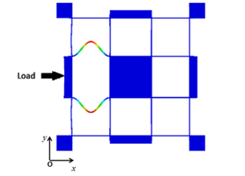
Fig. 1. Buckling point when a load is applied along X
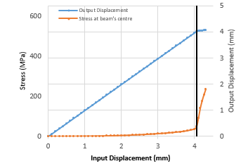
Fig. 2. Stress and output displacement response to a large input displacement
The output displacement is also compared with the input displacement. The axial deformation of the inner parallelogram beams causes the output displacement to be slightly different from the input displacement. The results show that for an input displacement between 0 and 2.2mm, the difference between the input and the output displacement can reach 5µm.
2.2. Coupling analysis
It is desirable for a compliant stage to have a minimal cross-coupling between the axes of motion. An analysis is therefore carried out to evaluate the parasitic displacement along the Y direction when a load is applied in the X direction. An input displacement of 2.2mm is first applied along the Y direction, as presented in Fig. 3. The maximum parasitic displacement is 65μm (Fig. 4), corresponding to a coupling of 3%. An input displacement of 2.2mm is then gradually applied along the X direction. The results show that the maximum displacement error along Y is 67µm (Fig. 5).
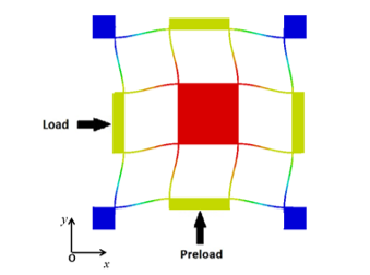
Fig. 3. Deformed XY motion stage with input displacement applied along X and Y directions
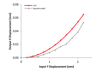
Fig. 4. Measurements of the parasitic displacement for single direction loading
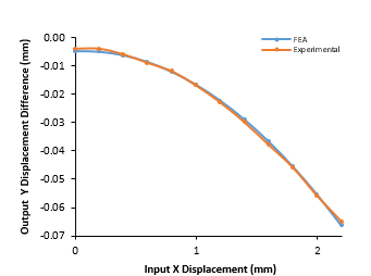
Fig. 5. Coupling error between X and Y
2.3. Dynamic analysis
In order to limit the effect of external vibrations, the first natural frequency of the compliant stage must be kept as high as possible. A high ratio between the first two natural frequencies and the third natural frequency is also desirable as it guarantees that the stiffness along the two directions of motion is much lower than the stiffness along all other directions, thus avoiding unwanted motion. The stiffness ratio of compliant stages usually lies between 2 and 5 [4, 5, 10, 24-26]. A dynamic analysis of the stage is carried out with ABAQUS using the Lanczos Eigen solver (Fig. 6). The first two modes correspond to simultaneous vibrations along both the X and Y-axes, which occurs at 55.8Hz. The third mode, corresponding to a rotation around the Z-axis occurs at 249.5Hz. Finally, the fourth mode, corresponding to vibrations along the Z axis occurs at a frequency of 313.3Hz. The ratio between the first two natural frequencies and the third one is greater than 4.
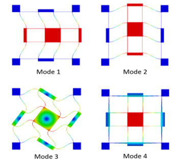
Fig. 6. Modal analysis results from FEA
3. Compliant XY Micro-motion Stage Fabrication and Testing
Most of the compliant stages reported in the literature are fabricated using Wire Electric Discharge Machining (WEDM). This technique allows for tight tolerances and a smooth surface finish. However, it is costly. Laser cutting and CNC machining were also considered but these processes are not suitable for machining 0.5mm thick beams. The first one would melt the beams and the second one would bend the beams because of the cutting force applied. The stage was fabricated using (Fig. 7). Corners of 0.5mm radius have been added to reduce the stress concentration. The stage is driven by two VCAs from Moticont (LVCM-051-064-02) with a 12.7mm stroke, 68.2N continuous force and a force constant of 21.6N/A. The moving coils are guided using high accuracy preloaded miniatures guides from SKF (LZMHS12-37T2P1). The VCAs are controlled by two Ingenia Pluto Drives, allowing for a position command resolution of 1.07µm over ±2.2mm along both directions using a 12-bit Analogue to Digital converter (ADC). The displacement of the actuators is measured using two linear encoders from Renishaw (ATOM4T0-150) with a resolution of 100nm.
3.1. Force-displacement test
A test is carried out to establish the relationship between the input displacement and the reaction force. The input displacement along the X-axis it maintained at 0mm while it is varied from 0mm to 2mm along the Y-axis. The linear encoders are used to measure the position of the VCAs. As the servo drives include a built-in current sensor, the force is derived from the current using the VCA’s force constant. The results are shown in Fig. 8. The force error of the first few readings is due to the internal friction in the bearings and can be neglected. The maximum force error, occurring at 2mm, is 11.1% when compared with FEA.
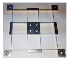
Fig. 7. Fabricated compliant XY micro-motion stage
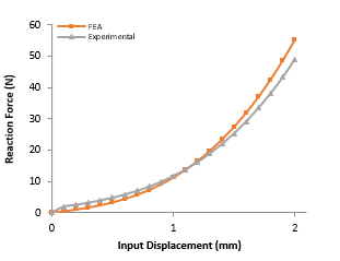
Fig. 8. Stiffness along a single direction
3.2. Frequency response analysis
In order to obtain the frequency response of the XY motion stage, a testing rig is set up to allow the stage to vibrate freely. An impulse is used to generate free vibrations which are measured along the X, Y and Z axes using a 3-dimensional accelerometer (ICP-T356A16), placed at the centre of the stage. The sensitivity of the accelerometer is 100mV/G and its output signal is processed by a Dual Channel Accelerometer Amplifier (FE-376-IPF) and recorded using a National Instruments data acquisition card (6008) with a sampling rate of 10kHz.
Labview is used to obtain the frequency domain response of each direction of motion using the Fast Fourier Transform (FFT). The testing rig setup is presented in Fig. 9. A peak in amplitude in each spectrum corresponds to the natural frequency along the corresponding direction of motion. The results are then compared with FEA, taking into account the mass of the accelerometer. The recorded resonant frequencies are 47Hz along the X and Y-axes and 267Hz along the Z-axis. When compared with FEA, the corresponding errors are 15.8% along the X and Y-axes and 14.8% along the Z-axis respectively. This error can be due to the mounts applying a small preload in the beams when being screwed.
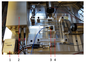
Fig. 9. Experimental vibration test setup. 1) Data acquisition card, 2) Amplifier, 3) 3D accelerometer, 4) Compliant XY motion stage
4. Dual-Range Positioning XY Micro-motion Stage
The assembled stage is presented in Fig. 10. It consists of a platform directly fixed to the centre of the compliant stage. Two small plates are mounted on the platform and are used as a target to measure the output displacement of the XY motion stage. The total moving mass is approximately 1kg.
4.1. Input Position Control
The input position control of the XY motion stage controls the linear displacement of the VCAs with a Proportion-Integral-Derivative (PID) loop using the two linear encoders as feedback. The output displacement (i.e. displacement of the moving platform) is measured with two capacitive sensor heads (CS1) from Micro-Epsilon with DT6110 controllers, giving a resolution of 100nm and a reading accuracy of 0.5µm over a range of 1mm. These sensors are mounted on a carrier and are moved along a guiding rail using two Firgelli L12-P micro linear actuators with a 10mm stroke and ±0.1mm repeatability.

Fig. 10. Fabricated XY motion stage
The input displacements along the X and the Y directions are controlled with LABVIEW 2014 through the analogue outputs of a Labjack U6 Pro data acquisition card.
To begin with, a single direction displacement test is carried out over a range of 0mm to 2.2mm along Y. The results show that the difference between the input and the output displacement is 4µm and that the parasitic translation along the transverse direction is 53µm (Fig. 4), corresponding to a coupling of 2.4%.
A bi-directional loading test is then carried out. The input displacement of 2.2mm previously applied along the Y direction is maintained and an input displacement of 2.2mm is gradually applied along the X direction. The results are presented in Fig. 5. The first observation made is that the results are in accordance with FEA, where the maximum error is less than 3µm for 2.2mm input displacement. The second observation is that the maximum recorded parasitic displacement is 50µm.
4.2. Dual-range positioning
The observations made from the input position control test show that there is a coupling between the two axes of motion that cannot be predicted when moving the stage along both directions simultaneously. There is also a difference between the input and the output displacement of up to 14µm. To compensate for this positioning error, a set of high resolution sensors is added to the system in order to directly measure the output displacement of the stage. These sensors are mounted on a carrier and are moved along a guiding rail using two Firgelli L12-P micro linear actuators with a 10mm stroke and ±0.1mm repeatability. The dual-range positioning procedure for each direction of motion is as follow:
- The stage is moved to its desired position in open-loop mode (coarse positioning)
- The high resolution sensors are moved close to the moving platform and the relative position is recorded and used as the initial position for the next step
- The positioning error is measured using an external system
- The stage is moved by the positioning error measured in closed-loop mode using the feedback from the high resolution sensors (fine positioning)
A second PID loop is added to control the output displacement of the stage using the readings from the high resolution sensors. The simplified plant model is presented in Fig. 11. The gains are tuned using the trial-and-error method and will be refined at a later stage if necessary.
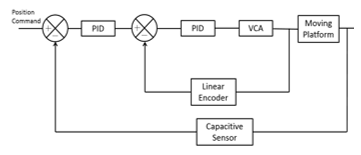
Fig. 11. Fine positioning control loop for the XY micro-motion stage
The external system used to measure the positioning error depends on the system in which the XY motion stage is integrated. This choice is up to the user. For instance, a high resolution vision system can be used to measure the position of the moving platform on which a calibration grid is placed. Alternatively, a coordinate measurement machine (CMM) was used in [23] to measure the positioning error.
Sensor selection
The choice of high resolution sensor is critical, however it involves a trade-off between the cost of the system and the measuring accuracy . Table 2 presents a qualitative analysis of the four types of sensors considered for this application based on quotations from RENISHAW®, KEYENCE Ltd. and MICRO-EPSILON Ltd. The most suitable solution in terms of this trade-off between cost and accuracy is the capacitive sensor. Therefore, the sensors used to measure the open-loop behaviour of the compliant stage are reused for the closed-loop control of the fine positioning, along with the linear actuators. The dual-range setup of the XY motion stage is presented in Fig. 12.
Testing
Since the capacitive sensors directly measure the position of the stage, they can be used to estimate the relative positioning accuracy. It is assumed that due to the nonlinear stiffness of the compliant stage, the force disturbance is higher for large displacements. Therefore, a test is carried out for an input displacement of 0mm along both directions and then for 2.2mm along both directions. The sensors’ readings are recorded for a period of 20 seconds in fine positioning mode and the accuracy is estimated from the maximum amplitude of oscillation once the steady state is reached. Fig. 13 shows the steady state response along both directions for 0mm loading. It can be clearly seen that the maximum amplitude of oscillation is smaller than ±0.5µm, which is beyond the reading accuracy of the capacitive sensors. Fig. 14 shows the steady-state response for 2.2mm bidirectional loading. The amplitude of oscillation increases and reaches ±2µm. This oscillation is due to the nonlinearities arising from the compliant stage. Additionally, the resolution of the analogue to digital converter (ADC) used to read the position command sent by the data acquisition card is only 12-bits. This corresponds to an incremental position resolution of 1.12µm. Controllers with a higher resolution would allow for a higher positioning accuracy.
5. Conclusion
A compliant XY micro-motion stage made from Aluminium 7075-T6 was characterised and fabricated, with a travel range of ±2.2mm 2.2mm and a coupling of 2.4%. The simulation results in terms of working area and stiffness are in accordance with FEA. The maximum displacement error of the micro-motion stage measured in coarse positioning mode was 67µm. The concept of dual-range manipulation was therefore introduced using capacitive sensors for the fine positioning. The relative positioning accuracy was reduced to less than ±2µm in the worst-case scenario. This error can be reduced by using higher resolution motor controllers and sensors. Therefore, there is a great potential for compact, low-cost and high accuracy micro-motion using dual-range positioning. The stage will later be integrated in a hybrid miniaturised product assembly system.
Table 2. Sensors’ rating
| Sensor | Accuracy | Sensing Range | Cost | Environmental Sensitivity |
| Capacitive | +++ | – | + | + |
| Interferometer | +++ | + | — | + |
| Eddy current | + | — | – | +++ |
| LVDT(1) | — | +++ | +++ | +++ |
(1) Linear Variable Differential Transformer
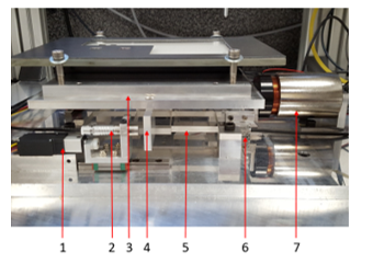
Fig. 12. Side view of the XY motion stage. 1) Linear actuator, 2) Capacitive sensor head, 3) Moving Platform, 4) Target, 5) Compliant XY stage, 6) Linear encoder, 7) VCA
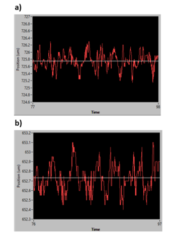
Fig. 13. Capacitive sensors readings in fine positioning mode at position 0mm along a) the X-axis, and b) the Y-axis
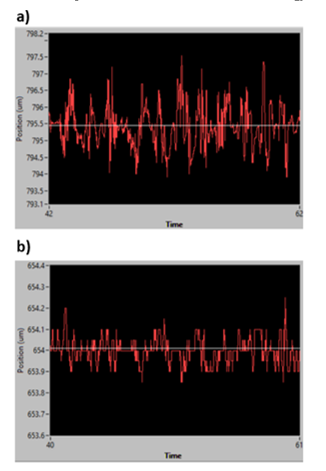
Fig. 14. Capacitive sensors readings in fine positioning mode at position 2.2mm along a) the X-axis, and b) the Y-axis
Acknowledgment
The authors would like to thank the financial support from the Engineering and Physical Sciences Research Council (EPSRC), UK under Grant No. EP/K018345/1.
- F. Wang, C. Liang, Y. Tian, X. Zhao, and D. Zhang, “A Flexure-Based Kinematically Decoupled Micropositioning Stage with a Centimeter Range Dedicated to Micro/nano Manufacturing,” IEEE/ASME Transactions on Mechatronics, vol. PP, pp. 1-1, 2015.
- D. Jie, L. Sun, Y. Liu, Y. Zhu, and H. Cai, “Design and Simulation of a Macro-micro Dual-drive High Acceleration Precision XY-stage for IC Bonding Technology,” in Proceeding of the 6th International Conference on Electronic Packaging Technology, 2005, pp. 161-165.
- Y. Tian, B. Shirinzadeh, and D. Zhang, “Design and dynamics of a 3-DOF flexure-based parallel mechanism for micro/nano manipulation,” Microelectronic Engineering, vol. 87, pp. 230-241, 2010.
- G. Hao and J. Yu, “A Completely Kinematostatically Decoupled XY Compliant Parallel Manipulator through New Topology Structure,” in Proceedings of the IFToMM Workshop on Fundamental Issues and Future Research Directions for Parallel Mechanisms and Manipulators, 2014.
- S. Xiao and Y. Li, “Design and analysis of a novel flexure-based XY micro-positioning stage driven by electromagnetic actuators,” in Proceeding of the International Conference on Fluid Power and Mechatronics, 2011, pp. 953-958.
- Y. Li, J. Huang, and H. Tang, “A Compliant Parallel XY Micromotion Stage With Complete Kinematic Decoupling,” IEEE Transactions on Automation Science and Engineering, vol. 9, pp. 538-553, 2012.
- J. Yu, Y. Xie, Z. Li, and G. Hao, “Design and Experimental Testing of an Improved Large-Range Decoupled XY Compliant Parallel Micromanipulator,” Journal of Mechanisms and Robotics, vol. 7, pp. 044503-044503, 2015.
- G. Hao and X. Kong, “A Novel Large-Range XY Compliant Parallel Manipulator With Enhanced Out-of-Plane Stiffness,” Journal of Mechanical Design, vol. 134, pp. 061009-061009, 2012.
- Q. Xu, “New Flexure Parallel-Kinematic Micropositioning System With Large Workspace,” IEEE Transactions on Robotics, vol. 28, pp. 478-491, 2012.
- G. Hao, Q. Meng, and Y. Li, “Design of Large-range XY Compliant Parallel Manipulators Based on Parasitic Motion Compensation,” in Proceedings of the ASME International Design Engineering Technical Conferences & Computers and Information in Engineering Conference (IDETC/CIE), 2013
- C.-H. Liu, W.-Y. Jywe, Y.-R. Jeng, T.-H. Hsu, and Y.-t. Li, “Design and control of a long-traveling nano-positioning stage,” Precision Engineering, vol. 34, pp. 497-506, 2010.
- Y. Park, “Precision motion control of a three degrees-of-freedom hybrid stage with dual actuators,” IET Control Theory & Applications, vol. 2, pp. 392-401, 2008.
- Y. M. Choi and D. G. Gweon, “A High-Precision Dual-Servo Stage Using Halbach Linear Active Magnetic Bearings,” IEEE/ASME Transactions on Mechatronics, vol. 16, pp. 925-931, 2011.
- S. Jing-Chung, W. Chia-Hung, C. Bor-Yu, and J. Wen-Yuh, “Control of a Long-stroke Precision Scanning Stage,” in Proceeding of the Mediterranean Conference of Control and Automation (MED), 2014, pp. 311-315.
- S. Jing-Chung, J. Wen-Yue, L. Qun-Zhong, and W. Chia-Hung, “Control of a High Precision Positioning Stage,” in Proceeding of the 7th IEEE Conference on Industrial Electronics and Applications (ICIEA), 2012, pp. 931-935.
- Y. Song, J. Wang, K. Yang, W. Yin, and Y. Zhu, “A dual-stage control system for high-speed, ultra-precise linear motion,” Int J Adv Manuf Technol, vol. 48, pp. 633-643, 2009.
- S. Kwon, W. K. Chung, and Y. Youm, “On the Coarse/fine Dual-stage Manipulators with Robust Perturbation Compensator,” in Proceeding of the IEEE International Conference on Robotics and Automation (ICRA), 2001, pp. 121-126 vol.1.
- L. Zhang, Z. Long, J. Cai, and J. Fang, “Design of a linear macro–micro actuation stage considering vibration isolation,” Advances in Mechanical Engineering, vol. 7, pp. 1 – 13, 2015.
- F. Jiwen, L. Zhili, Z. Lufan, and N. Longsheng, “Driving Process and Control Analysis in Macro-micro Dual Stage,” in Proceeding of the IEEE International Conference on Information and Automation (ICIA), 2013, pp. 37-42.
- H. Tang and Y. Li, “Design, Analysis, and Test of a Novel 2-DOF Nanopositioning System Driven by DualMode,” IEEE Transactions on Robotics, vol. 29, pp. 650-662, 2013.
- Q. Xu, “Design and Testing of a Novel XY Micropositioning Stage with Dual Ranges and Resolutions,” in Proceeding of the IEEE International Conference on Robotics and Automation (ICRA), 2014, pp. 2351-2356.
- X. Herpe, R. Walker, X. Kong, and M. Dunnigan, “Analysis and Characterisation of a Kinematically Decoupled Compliant XY Stage,” in Proceeding of the 21st International Conference on Automation and Computing (ICAC), 2015, pp. 1-6.
- X. Herpe, R. Walker, M. Dunnigan, and X. Kong, “Design, Fabrication and Testing of a Hybrid Micro-motion XY stage Driven by Voice Coil Actuators,” in Proceeding of the International Conference for Students on Applied Engineering (ICSAE), 2016, pp. 153-158.
- L.-J. Lai, G.-Y. Gu, and L.-M. Zhu, “Design and control of a decoupled two degree of freedom translational parallel micro-positioning stage,” Review of Scientific Instruments, vol. 83, p. 045105, 2012.
- Y. Li and Z. Wu, “Design, analysis and simulation of a novel 3-DOF translational micromanipulator based on the PRB model,” Mechanism and Machine Theory, vol. 100, pp. 235-258, 6// 2016.
- K.-B. Choi and D.-H. Kim, “Monolithic parallel linear compliant mechanism for two axes ultraprecision linear motion,” Review of Scientific Instruments, vol. 77, p. 065106, 2006.