A Reconfigurable Metal-Plasma Yagi-Uda Antenna for Microwave Applications
A Reconfigurable Metal-Plasma Yagi-Uda Antenna for Microwave Applications
Volume 2, Issue 3, Page No 441-448, 2017
Author’s Name: Giulia Mansutti1, a), Davide Melazzi2, Antonio-Daniele Capobianco1
View Affiliations
1Department of Electrical and Information Engineering, University of Padova, Via G. Gradenigo 6/B, 35131, Padova, Italy
2CISAS G. Colombo, University of Padova, Via Venezia 15, 35131, Padova, Italy
a)Author to whom correspondence should be addressed. E-mail: giulia.mansutti@gmail.com
Adv. Sci. Technol. Eng. Syst. J. 2(3), 441-448 (2017); ![]() DOI: 10.25046/aj020357
DOI: 10.25046/aj020357
Keywords: Plasma Antennas, Yagi-Uda Antenna, Microwave Antennas, Reconfigurable Antennas

Export Citations
This paper is an extension of the work originally presented at the European Microwave Conference (EuMC) about a reconfigurable hybrid metal-plasma Yagi-Uda antenna operating at 1.55 GHz: this antenna consists of metallic reflector and active element and two plasma directors. The conference work showed through full-wave numerical simulations (CST Microwave Studio) how it is possible to achieve reconfigurability with respect to the gain by turning on/off the plasma discharges. However the model that was used to represent the plasma discharges was quite ideal, so one comment that was provided questioned the actual possibility of achieving reconfigurability in a real system.
Consequently we performed extensive measurements of different plasma discharges and thanks to the collected data, we noticed some important differences between the full-wave numerical model of the plasma that we used in the conference paper and the actual plasma discharges that were generated in the experimental setup: the dielectric vessel and the metallic electrodes used respectively to confine and generate the plasma have an influence on the radiation pattern of the antenna and so they must be included in the design procedure; the cylindrical plasma discharge is much easier to realize when the cylinder diameter is at least 3mm; and finally the collision frequency of the plasma in realistic cases is pretty higher than the one adopted in our previous work.
Therefore this work presents a feasibility study of a more detailed and realistic model of our antenna with respect to the plasma discharges. We will show that reconfigurability can still be achieved through a proper design of the overall antenna, thus paving the way to an actual realization of the proposed reconfigurable Yagi-Uda.
Received: 05 April 2017, Accepted: 03 May 2017, Published Online: 24 May 2017
1. Introduction
Traditional antennas exploit metallic components to radiate and/or receive electromagnetic waves. In recent years there has been an increasing interest in another type of antennas, namely Gaseous Plasma Antennas (GPAs), whose radiating properties rely on partially or fully ionized gas rather than on metallic conductors [1-8]. The gas is confined into dielectric vessels such as glass cylinders (but the enclosure can be of any shape, e.g., monopoles and loops, and of any dielectric material) and the plasma can be turned on and off very rapidly (on time scales the order of milliseconds or microseconds) by different excitation means [3]. In the off state, the plasma reverts to a neutral gas that is confined in a dielectric holder, thus being transparent to any electromagnetic (EM) waves; when the plasma is turned on, it behaves as an electrical conductor that is able to transmit and receive EM signals.
1.1. Gaseous Plasma Antennas: Advantages
Plasma antennas have a number of potential advantages over conventional metal antennas since their properties can be electrically (rather than mechanically) controlled. This makes plasma antennas appealing for a number of applications, some of which are briefly discussed in the followings [4].
First of all, when a plasma discharge is unenergized, the gas reverts to its neutral state and so it stops behaving as a conductor. This feature makes plasma antennas difficult to be detected by radars, once the plasma vessel and excitation system are properly designed and if the antenna is energized only when the communication takes place. This property leads to a potential interest in plasma antennas for military applications.
Secondly, plasma antennas are transparent to EM waves whose frequency is above the plasma frequency; this feature makes plasma antennas interesting when dealing with appli- cations that need many antennas (or antenna arrays) used for different communication systems that must be stacked together due to space constraints (e.g., shipborne maritime communications) and that operate at different frequencies. In this case plasma elements are an interesting alternative to conventional metallic ones since they can provide significantly lower mutual coupling values among the different arrays; as a matter of fact, unenergized plasma elements do not interfere with active elements, and the coupling among plasma antennas working at different frequencies is significantly lower than the one provided by metallic antennas.
Additionally, plasma elements can be energized and de- energized on time scales of microseconds; as a result, the signal degradation caused by antenna ringing can be greatly reduced by using a plasma antenna transmitting at high rates and that is switched off at the end of each bit.
Finally, the radiation properties of a plasma antenna can be changed by electrically controlling the plasma parameters (e.g., density), which can be achieved by tuning the power delivered to the plasma. Therefore plasma antennas can be rapidly reconfigured with respect to their radiation pattern, input impedance, and working frequency.
1.2. Gaseous Plasma Antennas: Issues
Nevertheless, the usage of plasma discharges as antennas in communication systems can be hindered by several issues such as the noise introduced by the plasma, the complexity of the plasma antenna, and the availability of suitable technology solutions to generate the plasma.
The noise introduced by the plasma is strongly related to the way the plasma is generated, and this fact has been holding back the use of plasma antennas for many years. Different plasma generation techniques are available: laser-initiated atmospheric discharge [5], DC/AC discharge [6], and radio-frequency (RF) surface-wave plasmas [7]. Both DC and low-frequency AC methods introduced a rather high noise level when generating the plasma. RF surface wave generation and the pulsing power technique made it possible to obtain not only lower noise levels, but also higher plasma density and reduced power consumption [3].
Another obstacle to the exploitation of plasma antennas can be identified in the inherent complexity of plasma antennas. Specifically, a plasma antenna comprises not just the plasma, but also the equipment needed to generate it (e.g., the metallic electrodes in the case of a RF surface-wave-generated plasma). Furthermore, the plasma density in an actual plasma discharge is nonuniform, with a nonuniformity that depends on the plasma generation technology; before considering the actual realization of a plasma antenna, it is therefore necessary to develop a representative prototype of the plasma discharge the antenna will be comprised of, and to measure the plasma density therein. As a result, the presence of electrodes, and the nonuniform plasma distribution within the discharge are expected to affect the radiation properties of the actual plasma antenna, and are to be taken into account in the design, and realization of an actual plasma antenna.
Other critical aspects towards the realization of an actual plasma antenna, are the availability of the proper technology to ignite, and sustain the plasma, and the capability of developing customized dielectric vessels whose shape and dimensions must be carefully chosen according to the antenna type (e.g., monopole, dipole) and operating frequency.
1.3. Original Contribution and Paper Organization
In the proof of concept of a hybrid metal-plasma Yagi-Uda antenna presented in [1], two plasma discharges have been used as antenna directors to achieve reconfigurability with respect to the gain; specifically, the gain has been controlled by turning either on or off the plasma directors. In the full-wave numerical preliminary study that was performed in CST Microwave Studio [8], the plasma directors were ideally modeled as two cylinders made of a uniform dispersive Drude material, i.e., neglecting the presence of the dielectric tubes into which the plasma is confined and of the plasma generation equipment, i.e., the metallic electrodes attached at the two edges of the dielectric cylinder. Moreover we have modeled the off state of the plasma directors simply excluding the plasma elements from simulations. Therefore the comment that was made in the review process was related to the actual possibility of our proposed antenna to achieve reconfigurability in a more realistic scenario.
The aim of this work is to present a feasibility study of a realistic version of our hybrid metal-plasma Yagi-Uda antenna with some major differences with respect to the ideal model provided in [1]: (i) the plasma elements comprise the dielectric tubes and the electrodes; (ii) the collision frequency and plasma dimensions have been set now to more realistic values obtained through experimental characterizations of different plasma discharges; (iii) the off-state of the plasma directors is modeled including the dielectric tubes filled with neutral gas (i.e., unenergized plasma) in the simulations; and finally (iv) the overall design of the Yagi-Uda antenna was revised according to the above-mentioned differences.
The rest of the paper is organized as follows. In Section II the model of our new version of the hybrid metal-plasma Yagi-Uda antenna is described in details; Section III is dedicated to the results and related discussion with a particular focus on the comparison with our previous work [1]; finally in Section IV conclusions are reported.
2. Antenna Design
The aim of this work is to investigate the capability of achieving reconfigurability for a realistic metal-plasma Yagi- Uda antenna whose reflector and active element are made of metal while the directors are plasma discharges (as the one depicted in Figure 1). Therefore the substantial difference with respect to the work that was made in [1] involves the modelization of the plasma directors: more realistic values of the discharge diameter and collision frequency have been chosen according to typical values that were obtained from measurements of different implemented plasma discharges prototypes; moreover the dielectric vessels and electrodes used to generate the plasma are present.
The starting point for our analysis was then the modelization of the ideal plasma discharge, i.e. the plasma material that is confined into the glass vessel in the real plasma director. A weakly ionized plasma has been assumed in this work and it has been represented by means of a cold fluid model [9] by making the following assumptions.
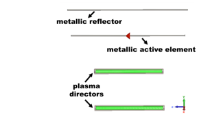
Figure 1. Design of the realistic Yagi-Uda antenna in CST Microwave Studio [8].
The weakly ionized gaseous plasma is modeled as a dispersive material that is suitably represented (both theoretically and in CST) as a Drude material. This provides the expression of the relative permittivity of the plasma εr as a function of the plasma parameters and of the operating frequency of the antenna:![]()
where ω = 2πf is the angular frequency of the incident EM wave (i.e., the signal), ν is the momentum-transfer collision frequency of electrons with heavy particles (ions/atoms), ωp=[ne2/meε0]1/2 is the electron plasma frequency, me and e are the electron mass, and charge respectively, ne is the local plasma electron density that is assumed to be uniform within the discharge and ε0 is the free space permittivity.
Some of these parameters are unchanged with respect to [1]: the operating frequency of the antenna is 1.55 GHz, and the plasma frequency is ωp = 178.4 · 109 rad/s since it has been shown by experimental measurements that this is an easily achievable value in real scenarios.
Regarding the collision frequency that accounts for the dissipation processes inside the plasma, this has been chosen significantly different from [1]: it is ν = 2.5067 · 109 s-1 instead of ν = 0.10328 · 109 s-1, i.e., much higher, since in actual realization of plasma discharges this is a more realistic value.
Therefore the values of εr are significantly different with respect to [1] and this can be clearly evinced from Figure 2 in which the real and imaginary parts of the relative permittivity are reported for the two scenarios. At the frequency of interest 1.55 GHz the real and imaginary parts of εr are Re{εr} = -314 and Im{εr} = -81 in this work, while they were Re{εr} = -334, Im{εr} = -4 in [1]. There is an important difference between the values of Im{εr} in the two cases: the great increase in the imaginary part of the permittivity (that translates in an increase in the losses of the antenna) is caused by the substantial change in the collision frequency that is much higher now and that indeed accounts for the dissipation processes inside the plasma.
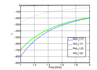
Figure 2. Comparison between the relative dielectric permittivity of the dispersive plasma in this work and in [1] (respectively (2) and (1) in the legend): imaginary part (dotted black line for (2), dash-dotted red for (1)) and real part (solid green for (2), dashed blue for (1)).
The length of the discharge was set according to a simplified model described in the followings. The cylindrical plasma column behaves as an open waveguide that can sustain surface- wave propagation and that therefore radiates significantly due to the breaking of the translational symmetry: this happens during the antenna operation mode, i.e., when the angular frequency ω = 2πf is much lower than the plasma frequency ωp. This behaviour of the cylindrical plasma bar has been verified through a simplified analytical model according to which, for an infinitely long column of uniform non-magnetized plasma endowed with relative dielectric permittivity εr, the dispersion relation for the surface wave that propagates along the column is given by [7]: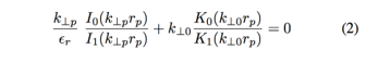
where rp is the plasma radius, k⊥p = (β2 – ω2εr/c2)1/2, k⊥0 = (β2 – ω2/c2)1/2 are the transverse propagation constants in the plasma and in free space, and β denotes the propagation constant along the plasma column; and finally, Ii , and Ki , i = 0, 1, are modified Bessel functions of the first and second kind, respectively.
The solution of (2) yields the so-called dispersion relation ω = ω(β) of the surface wave. Since the plasma column has finite length, it is expected that suitable combinations of progressive and regressive surface waves along the plasma-air interface can satisfy the boundary conditions at the ends of the column, and thus give rise to standing surface waves or modes of the open cavity resonator.
Exploiting the dispersion relation it is possible to calculate the resonance frequency of a plasma column with given dimensions and therefore it is possible to calculate the length of the plasma column in order to have it resonating at a desired frequency.
According to traditional RF antenna design rules, the column should resonate at a given frequency f when its length is approximately half the wavelength in free space λ0. But since plasma is a dispersive medium, the plasma column in the UHF band shows an effective wavelength that is shorter than the one in free space, that means that the resonance frequency for a column of length L is downshifted. Therefore, the plasma column is significantly shorter than its metallic counterpart: its length has been ultimately set to 52mm (instead of λ0/2 = 96.8mm), a value obtained starting from λeff/2 and adjusted in order to optimize the performances of the overall Yagi-Uda antenna.
As far as the Yagi-Uda antenna model is concerned, its dimensioning follows the general rules of RF antenna design [10]: the reflector length is Lrfl = 0.5λ0 = 90.91 mm and the active dipole is Ldpl = 0.47λ0 = 85.45 mm. We considered a classic metal Yagi-Uda antenna in order to compare the performance of our solution with those of the standard design: in this case the metal directors length is approximately Ldir = 0.4λ0 = 73.82 mm. The distance between the reflector and the dipole is s1 = 0.25λ0 = 45.45 mm and the spacing between the dipole and the directors and the two directors is s2 = 0.34λ0 = 61.82 mm. All the elements have the same radius, i.e., r = 0.003λ0 = 0.54 mm. In CST Microwave Studio the dipole is fed through a 50 Ω discrete face-port that is placed in a gap g = 1.4 mm.
As far as the simulative model of the plasma directors is concerned, we decided to include the dielectric vessels and the metallic electrodes used to generate the plasma in the CST simulations. The gaseous plasma is confined into a glass cylinder (pyrex material from CST library) of internal radius rint = rplasma = 3 mm and thickness of 0.6 mm: these values have been chosen according to real glass tubes that have been realized to confine the plasma in an experimental setup. Finally the glass cylinder is closed at the two extremities by two metallic electrodes of 1mm thickness that resemble those used to generate the plasma by RF surface wave technique. A detail of the director design in CST Microwave Studio is reported in Figure 3.
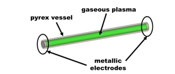
Figure 3: Design of the realistic plasma director in CST Microwave Studio [8].
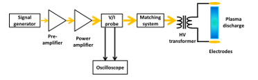
Figure 4. The scheme of the RF plasma generation system.
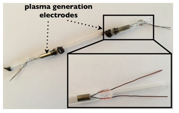
Figure 5. The experimental plasma discharge that has been used as director.
3. The Experimental Setup of the Plasma Director
To realize the plasma directors, we have relied on a ca- pacitive discharge [6] that has been driven by 50 Ω Radio Frequency (RF) power source; the RF power has been fed in the 1.8 ÷ 15 MHz range of frequencies through a matching network for efficient power transfer to the plasma, as illustrated in Figure 4. The signals are carried by means of RG-58 coaxial cables, while RF power is conveyed via RG-214 coaxial cables. The plasma has been generated by a couple of high voltage electrodes (see Figure 5) that have been placed internally at the far ends of the cylindrical pyrex vessel while being sealed with the prescribed argon gas atmosphere of 2 mbar. The pyrex vessel has an inner diameter of 3 mm, and an outer diameter of 4 mm; the two electrodes have been placed at a distance such that it is possible to realize a plasma column like the one identified in the antenna design phase.
To estimate the actual plasma density distribution within the plasma discharge, we have relied on a microwave interferome- ter [11], which is capable of plasma density measurements regardless of the gas type; specifically, the plasma density value is related to the phase shift produced on a microwave signal travelling through the plasma. The instrument works in the 1016 ÷ 7 · 1019 m-3 range of plasma density values, is movable along the plasma source, and measures density in a plasma slab that is extended across the diameter of the source (see Figure 6). The plasma frequency value that was used in this work (see Section II) agrees with the measurements that were performed.
4. Results and Discussion
In this section the main results concerning the realistic metal plasma antenna are reported and compared with those obtained in [1] for its ideal counterpart. The results were obtained through full-wave numerical simulations by means of CST Microwave Studio Suite [8].
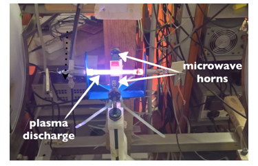
Figure 6. The experimental set-up with the plasma discharge between the two horns of the microwave interferometer for plasma density measurement.
The analysis was carried out in the frequency range 1 ÷ 2 GHz and concern mainly two metrics: (a) the reflection coefficient and the input impedance, (b) the radiation properties of the antenna, i.e., farfield gain and its reconfigurability together with radiation efficiency.
4.1. Reflection Coefficient and Input Impedance
As a first step, Figure 7 reports the absolute value of the reflection coefficient |S11| for the Yagi-Uda antenna with zero and two metal directors, for the hybrid Yagi-Uda with two ideal plasma directors [1] and for the antenna with the two realistic directors (as described in Section II). These three configurations were chosen as representative since they account for the starting condition, i.e., the antenna with no directors that is designed to resonate at f = 1.55 GHz, and the condition of maximum possible detuning for the antenna, i.e., when two directors are present; the other cases involving one director are omitted for ease of read of the graphs but are similar to and in perfect agreement with the results shown in the figure. As it can be seen, the absolute value of the reflection coefficient at the operating frequency is well below -15 dB in all the three cases, thus confirming that the realistic plasma discharges that were conceived in this work do not detune the antenna. In Figures 8-9 the real and imaginary parts of the input impedance Z are reported again for the classic metal antenna, for the ideal hybrid Yagi-Uda and for the realistic hybrid antenna both with two directors. It can be seen how at the operation frequency f = 1.55 GHz, Im{Z} is almost zero for the three antennas, while Re{Z} changes: it is 45 Ω for the classic antenna and for the hybrid ideal one, while it is 43 Ω for the realistic one. It can be noticed however how also in the case in which a realistic discharge is considered the idea of using a metal dipole as the active element of the antenna proves to be a good solution in order to avoid the matching issues caused by the low input impedance of plasma antennas [12].
4.2. Radiation Properties and Reconfigurability
As far as the reconfigurability of the antenna is concerned, Figures 10-11 depict the gain of the hybrid realistic Yagi-Uda antenna with zero, one and two directors in linear scale (for ease of read) in the E-plane (xz-plane) and H-plane (xy-plane) respectively.
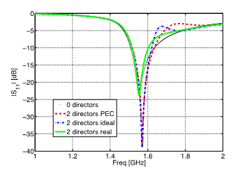
Figure 7. Absolute value of the reflection coefficient |S11| for the Yagi-Uda antenna with: no directors (dotted black line), two PEC directors (dashed red line), two ideal plasma directors (dash-dotted blue line) and two realistic plasma directors (solid green line).
As stated in Section II, when one or two directors are switched off, the vessel and electrodes have been included in the simulations and nonetheless we can see how reconfigurability with respect to the gain can still be achieved: the higher the number of active plasma directors, the higher the gain.
Then we compared the gain of the realistic hybrid antenna both with its ideal counterpart [1] and with the classic metal antenna. Figures 12-13 report the gain for the three antennas with one director switched on, on the E-plane and H-plane respectively: it can be seen how the gain of the antenna with the realistic plasma director is lower than those of the antenna with the ideal plasma director and than the one with the metal director (5.13 vs 6.02 and 6.25). Nonetheless the plot is in linear scale and therefore there is around 1 dB of difference between the maximum achievable gain in the three cases. The fact that the gain with the realistic plasma director is lower than in the case of the ideal one is reasonable considering that the collision frequency that accounts for the dissipation processes is considerably higher in the realistic case.
Figures 14-15 report the same plot but this time with both the plasma directors turned on. Analogous considerations can be made as in the previous case: the gain for the realistic antenna is 5.6 that is lower than that of the ideal one (6.63) and of course lower than the one of the classic Yagi-Uda (7.1); but again, the values are in linear scale so the difference between the gain of the ideal and realistic hybrid antenna is less than 1 dB.
The last case concerns the antenna when both the directors are turned off: in the ideal case, the directors were excluded from simulations, while in the realistic case, the dielectric vessels and electrodes are included. The results are not reported graphically since the two radiation patterns are almost identical. This proves, as it was expected, that the main factor that influences the radiation pattern of the antenna is the plasma collision frequency, i.e., the parameter that accounts for the dissipative processes and that in this work is significantly higher than in [1].
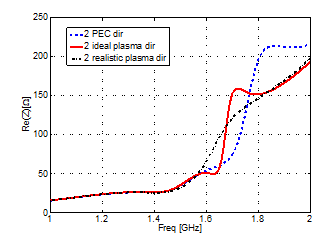
Figure 8. Real part of the input impedance of the Yagi-Uda antenna with: two PEC directors (dashed blue line), two ideal plasma directors (solid red line) and two realistic plasma directors (dash-dotted black line).
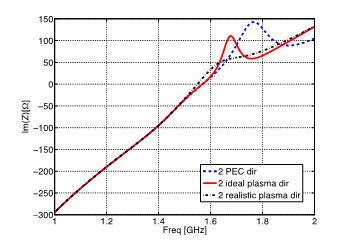
Figure 9. Imaginary part of the input impedance of the Yagi-Uda antenna with: two PEC directors (dashed blue line), two ideal plasma directors (solid red line), and two realistic plasma directors (dash-dotted black line).
As far as the efficiency is concerned, as expected this is lower in the realistic case in which losses are higher (this translates in a greater value of the collision frequency as commented previously): the efficiency is approximately 100 % for the metal Yagi-Uda, 98 % for the ideal hybrid Yagi-Uda and 80 % for the realistic one.
5. Conclusions
In this work the study and design of a reconfigurable metal- plasma Yagi-Uda antenna for microwave applications has been presented: plasma discharges have been suitably designed to be used as directors of the antenna in order to achieve reconfigu- rability with respect to the gain. These plasma directors were designed starting from [1] and they were modified in order to resemble more realistic plasma discharges: the dielectric vessel and metallic electrodes were included in the model and moreover the dimensions and plasma parameters of the discharges were set according to experimental measurements of real plasma antennas.
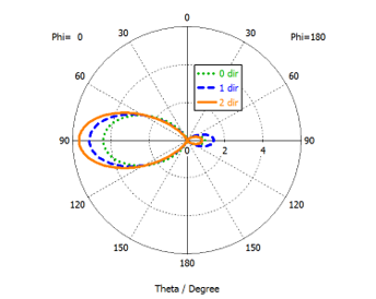
Figure 10. Farfield gain of the realistic hybrid antenna on the E-plane, i.e., xz-plane (see Figure 1) with zero (dotted line), one (dashed line) and two directors (solid line).
It has been shown that the performance of the antenna is very good as compared to [1]. Moreover it is clear from the results that reconfigurability with respect to the gain can still be achieved even with realistic plasma discharges used as directors. Of course, the radiation pattern is affected by the considerably higher value of the collision frequency, i.e., by the fact that dissipative processes are stronger in this case.
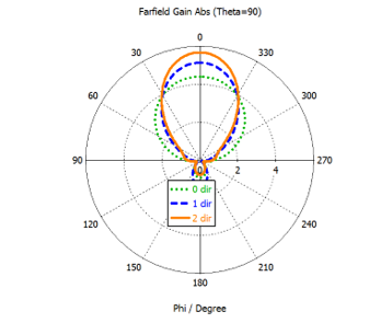
Figure 11. Farfield gain of the realistic hybrid antenna on the H-plane, i.e., xy-plane (see Figure 1) with zero (dotted line), one (dashed line) and two directors (solid line).
As a future step, we aim at considering plasma discharges with a non-uniform density, i.e., a density that changes axially along the cylindrical vessel and that resembles even better the behaviour of a realistic plasma discharge.
Therefore this study paves the way to the actual realization of the conceived hybrid metal-plasma Yagi-Uda antenna. However, it must be pointed out that, in order to characterize and measure our proposed antenna not only in terms of its reflection coefficient but also in terms of its radiation pattern, there are still some issues to face, mainly related to the rather complicated setup that is needed to ignite and sustain the plasma inside the two directors.
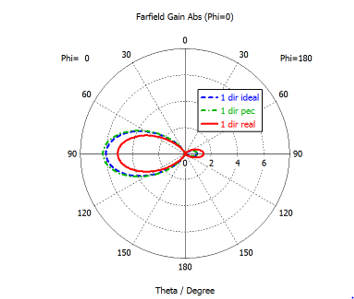
Figure 12. Farfield gain of the Yagi-Uda antenna on the E-plane, i.e., xz-plane (see Figure 1), with: one PEC director (dash-dotted green line), one ideal plasma director (dashed blue line) and one realistic plasma director (solid red line).
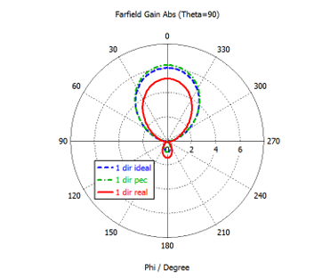
Figure 13. Farfield gain of the Yagi-Uda antenna on the H-plane, i.e., xz-plane (see Figure 1), with: one PEC director (dash-dotted green line), one ideal plasma director (dashed blue line) and one realistic plasma director (solid red line).
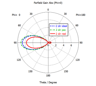
Figure 14. Farfield gain of the Yagi-Uda antenna on the E-plane, i.e., xz-plane (see Figure 1), with: two PEC directors (dash-dotted green line), two ideal plasma directors (dashed blue line) and two realistic plasma directors (solid red line).
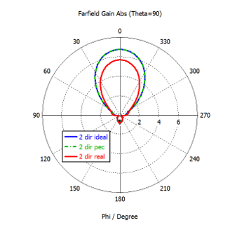
Figure 15: Farfield gain of the Yagi-Uda antenna on the H- plane, i.e., xz-plane (see Fig.(1)), with: two PEC directors (dash-dotted line), two ideal plasma directors (dashed blue line) and two realistic plasma directors (solid red line).
Acknowledgment
The authors acknowledge financial support from the University of Padova, project CPDA150022.
- G. Mansutti, D. Melazzi, and A.-D. Capobianco, “Hybrid metal-plasmaYagi- Uda antenna for microwave applications,” 46th European Microwave Conference (EuMC), London, UK, Oct. 2016, pp. 727-730.
- G. G. Borg, J. H. Harris, N. M. Martin, D. Thorncraft, R. Milliken et al. “Plasma as antennas: Theory, experiment and applications,” Phys. Plasmas, vol. 7, no. 5, pp. 2198–2202, May 2000.
- T. Anderson, ”Plasma Antennas,” Artech House, 2011.
- J. P. Rayner, A. P. Whichello, and A. D. Cheetham, “Physical characteristics of plasma antennas,” IEEE Trans. Plasma Sci., vol. 32, no. 1, Feb. 2014.
- T. Dwyer, J. Greg, D. Murphy, J. Perin, R. Pechacek, and M. Raileigh, “On the feasibility study of using an atmospheric discharge plasma as an RF antenna,” IEEE Trans. Antennas Propag., vol. 32, pp. 141–146, 1984.
- M. Lieberman and A. Lichtenberg, “Principles of Plasma Discharges and Materials Processing”, ser. Second Edition. John Wiley & Sons, Inc., 2005.
- M. Moisan, A. Shivarova, and A. Trivelpiece, “Experimental investigations of the propagation of surface waves along a plasma column,” Physics of Plasmas, vol. 24, p. 1331, 1982.
- CST Microwave Studio 2016, https://www.cst.com/products/cstmws.
- D. Swanson, “Plasma Waves,” Institute of Physics, Second ed., 2003.
- C. A. Balanis, Antenna theory: analysis and design, 3rd edition, Wiley,
- O.Tudisco et al., ”A microwave interferometer for small and tenuous plasma density measurements,” Rev. Sci. Instrum. 84, 2013.
- D. Melazzi, P. De Carlo, M. Manente, V. Lancellotti, and D. Pavarin, “Numerical results on the performance of gaseous plasma antennas,” International Conference on Electromagnetics in Advanced Applications (ICEAA), September 2015, pp. 569 – 572.