Fault Tolerant Inverter Topology for the Sustainable Drive of an Electrical Helicopter
Fault Tolerant Inverter Topology for the Sustainable Drive of an Electrical Helicopter
Volume 2, Issue 3, Page No 401-411, 2017
Author’s Name: Igor Bolvashenkova), Jörg Kammermann, Taha Lahlou, Hans-Georg Herzog
View Affiliations
Technical University of Munich (TUM), Department of Electrical and Computer Engineering, Institute of Energy Conversion Technology, Arcisstr. 21, 80333 Munich, Germany
a)Author to whom correspondence should be addressed. E-mail: igor.bolvashenkov@tum.de
Adv. Sci. Technol. Eng. Syst. J. 2(3), 401-411 (2017); ![]() DOI: 10.25046/aj020352
DOI: 10.25046/aj020352
Keywords: Electrical Helicopter, Traction Drive, Multilevel Inverter, Thermal Behavior, Reliability, Fault Tolerance

Export Citations
The paper describes the results of the system analysis of various options of electric inverter topologies for the use in the traction drive of an electrical helicopter. The paper explains the optimal choice, in terms of the design requirements and future operational conditions, and the type and topology of the electric inverter to supply the traction permanent magnet synchronous motor with the batteries. The main focus has been set on the study of the overload capacity, thermal behavior, and the fault tolerance of the multilevel electric inverter. In order to estimate these parameters, the Markov models of the multi-state system’s reliability evaluation were used.
Received: 05 April 2017, Accepted: 12 May 2017, Published Online: 22 May 2017
1. Introduction
Nowadays, according to the long-term plans for the electrification of various types of vehicles, the task of the electrification of air traffic has now become very important. First of all, the application of elec-tric drives is a promising one for small helicopters de-signed for search and rescue operations with a nom-inal power of 510 kW, a rotational speed of 400 rpm, and a voltage of 800 V. Regarding the choice of an op-timal electric inverter topology for the traction drive the main attention was paid to the flight safety.
The simplest solution would be to maximize the number of redundant equipment, but strict limita-tions on weight and dimensions do not allow this. The papers [1, 2] show that only multi-phase electric mo-tors are capable to satisfy the requirements to the fault tolerance ( 109 /h), set up for the electric traction drive of the helicopter.
Taking into account the safety and sustainability of helicopter’s operations, the relevant options for in-verter topologies were evaluated. Thus according to
- for the comparative analysis the semiconductor in-verters for 6-, 7-, and 9-phase motors were taken.
Due to the great relevance of the creation of elec-tric inverters for special applications, there are many publications describing the topologies and the analy-sis of inverters with different levels of fault tolerance for various vehicle types. The results of these studies were taken into account by the authors at carrying out of their investigations. Hence, the main task of this re-search is to find the decision, how it becomes possible to achieve the required values of the inverter’s fault tolerance.
2. Approach and Parameters for Evaluation
For each component of the helicopter’s traction drive, based on the project requirements and conditions of future operations, the most important parameters are:
- reliability and fault tolerance;
- weight, volume, and dimensions.
2.1 Reliability and Fault Tolerance
For the safety-critical aircraft applications accurate assessment of reliability and fault tolerance indices of the electric inverter at the design stage of the he-licopter is crucial for further operation.
The operating experience of electric inverters in-dicates that the most vulnerable elements of inverter are the capacitors, semiconductors, and printed cir-cuit board (PCB) [3, 4]. Statistical data of failure in various parts of inverter are shown in Figure 1. The main reason of the failures is the overheating of the semiconductors caused by current overloads, as can be seen in Figure 2.
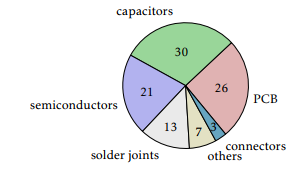
Figure 1: Failure statistics of the components [3].
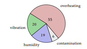
Figure 2: Causes for the failures [3].
Based on the above data charts, reliability level of an electric inverter EI can generally be estimated considering the reliability values of its components by the equation:
EI(t) = Ti (t) + Dj (t) + Ck(t) + Bn(t) (1)
where Ti (t), Dj (t), Ck(t), and Bn(t) are the fail-ure rates of the all components of electric inverter, respectively of transistor, diode, capacitor and printed circuit board.
In accordance with [3–6] the following failure cases were considered, shown in Figure 3.
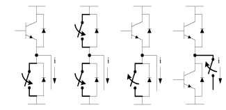
Figure 3: Considered inverter failures [6].
Thus, the considered failures are (Figure 3):
- single inverter switch short-circuit;
- phase-leg short-circuit;
- single inverter switch open-circuit;
- single phase open-circuit (internal or external).
In these cases for the fault-tolerant operation ei-ther the inverter module must be shut down or must be switched to the possibly existing redundant in-verter leg or module. Each of these modes is con-nected with a rapid increase in the current at the emergency site and an overload of semiconductors. On the basis of data on the standard overload capacity of power electronics has been plotted the graph pre-sented in Figure 4.
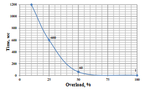
Figure 4: Overload capacity of the inverter.
The most of the fail operational modes caused by technological overloads. At the overload power losses occur in the p-n-transition and its temperature due to the low heat capacity increases dramatically. In the case of exceeding a certain critical temperature of p-n-transition, the semiconductor device fails. So over-heating temperature is the main parameter character-izing the overload capacity of semiconductor devices as can be seen in Figure 5.
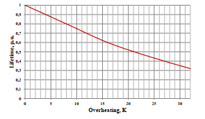
Figure 5: Dependency of the inverter’s lifetime on overheating.
So, the consequences of overload in failure oper-ational modes are overcurrent and overheating of an inverter, which lead to a reduction of the reliability indices of the motor and to a decrease in lifetime [7].
2.2 Weight, Volume, and Dimension
The modern options of the fault tolerant topolo-gies of electrical inverters [6, 8–10] have a different number of components designed for different values of operating parameters. Therefore, the number of components, the flexibility of their placement, and the inverter parameters are largely determining such important characteristics of the helicopter, such as weight, volume, and dimensions. The comparative analysis of these values for different inverter topolo-gies are presented in the next sections of this paper.
3. Topologies for the Comparative Analysis
The first part of this section explains the conventional topologies, such as 6-pulse-bridge (B6-bridge) and the H-bridge. However, the second part analyzes the use of multilevel inverters, i.e. cascaded H-bridge (CHB) inverters.
3.1 Conventional Full- and Half-Bridge Topologies
One of the previous papers [2] compared multi-phase permanent magnet synchronous motors (PSM) for safety-critical drive trains. As a result, 6-, 7-, and 9-phase motors are preferable in order to reach the re-quirements regarding fault tolerance. Hence, possible 9-phase machine topologies are presented in Figure 6, as well as in Figure 7. Those are commonly used and can be adapted to all different numbers of phases.
The already mentioned inverter topologies are compared for a failure case (open circuit) in one phase. This is also valid for a short circuit failure, if the fault is instantaneously detected and isolated, as described in [11, 12]. Hence, the advantage of H-bridges is the separation of every single phase in order to monitor failures. For this inverter topology compar-ison, an existing electrical machine with three phases serves as an exemplary machine for the failure sim-ulations. At first sight, the results can relatively be adapted to other power requirements.
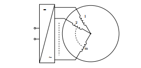
Figure 6: General visualization of a multi-phase topology with windings connected in one star.
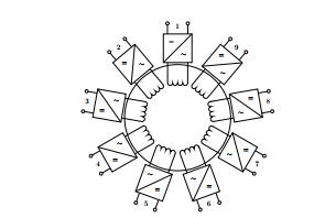
Figure 7: General visualization of a multi-phase mod-ular topology with galvancally insulated windings
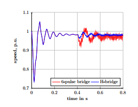
Figure 8: Simulation results for a failure case after 0.4 s for both the 6-pulse-bridge and the H-bridge considering speed over time.
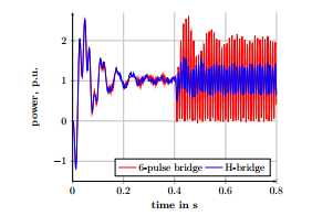
Figure 9: Simulation results for a failure case after 0.4 s for both the 6-pulse-bridge and the H-bridge considering power over time.
After the transient response of the simulation model, the failure takes place at 0.4 seconds and the results are shown in Figure 8 and Figure 9. The speed fluctuations are clearly visible for both machines in Figure 8, whereas the amplitude of the 6-pulse bridge is higher, as well as the speed ripple. Considering Fig-ure 9, the results show, that the power or torque ripple get a lot smoother for the H-bridge, since the peaks for the B6-bridge even drop down to 0. The peak to peak value equals up to 100% for the 6-pulse-bridge, com-pared to approximately 40% for the H-bridge
In summary, considering a one phase failure and hence fault tolerance, the H-bridge is recommend-able for machines with multiple phases, because of the lower power degradation. Due to the high requirements, the machine is already highly saturated in nominal operation; hence, overload in a failure case is not applicable. Thus, in case of a 6-pulse-bridge, three phases fail, since the inverter is unable to drive two out of three phases. In contrast, each H-bridge drives one phase and consequently in case one phase fails, eight phases still operate. Assuming an equally distributed power per phase, the H-bridge topology provides 89% of the nominal power and the B6-bridge only 67% respectively for a 9-phase machine. For the
-phase machine the situation gets even worse. However, after first analytical approximations and considering the application case, weight is 20%, vol-ume 60% higher, and the power losses are slightly higher (10%) for the H-bridge compared to the 6-pulse-bridge topology. This results out of the in-creased number of semiconductors being necessary for the H-bridge topology. Therefore, the next section includes the analysis of a multilevel inverter trying to solve the problems regarding weight, volume, and power losses, since there is no definitely preferred op-tion. [11–13]
3.2 Multilevel Inverter – Cascaded H-Bridge Inverter
Multilevel inverters offer several advantages com-pared to their two-level counterparts [14]: smaller power filters, smaller voltage ratings for semicon-ductors, lower switching frequencies, and less power losses. They offer also more modularity and are more reliable. The inverter with three H-bridges and the B6-bridge inverter need higher voltage range semi-conductors (1000V range).
Considering [15–17], CHB inverters with the lower number of components than other classic multilevel counterparts, such as the Neutral Point Clamped (NPC) or Flying Capacitor (FC), are the best candidate for the use in electric drives. They need more com-ponents than CHB and have less modularity, due to the central storage unit. The number of components (power switches, diodes and capacitors) for one phase with 17-level output voltage steps is: 288 for the NPC, 168 for the FC and 40 for the CHB (see Figure 10).
Figure 10 shows, that the cascaded H-bridge topol-ogy has the most advantages with more than 5-level. CHB inverters offer higher modularity and have the capability for embedding energy storage units in a split manner, given the existence of several submod-ules operating at low voltages (see Figure 13).
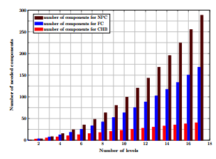
Figure 10: Number of components using three multi-level inverter topologies.
Table 1 shows the parameters of the system. It also shows the structure of the batteries used for the B6-bridge inverter with centralized energy source (bat-tery rack) and CHB inverter with decentralized en-ergy sources (battery modules). VL is the phase voltage of the machine, Vcell the battery cell voltage, Vmod the battery module voltage, and Vrack the battery rack voltage. The capacity/energy content of the storage units is neglected.
A multilevel inverter with 17 level output voltage steps needs 8 battery modules in each phase. The number of required submodules depends on the value of the minimal phase voltage of the machine and on the minimal battery module voltage Vbattmin and is calculated as follows:
| nsubmodules = | vL1 | = | 353 V | = 7:88 8 (2) | ||
| Vbattmin | 44:8V | |||||
Using a higher number of submodules the output voltage is near to a sinusoidal wave form and the har-monics on the electrical machine are lower.
The CHB inverter uses battery modules as shown in Figure 13. Each module is connected to an H-bridge with 4 MOSFETs. The use of MOSFETs enhances the efficiency of the CHB inverter, because of the low con-duction losses. Usually, IGBTs are used for a higher voltage range, such as for B6-bridge inverters.
The prototype of the three phase CHB inverter is compared to a commercial B6-bridge inverter (Siemens S120) with the same nominal power 36 kW, taking into account weight, volume, and efficiency. The power-to-volume ratio of the B6-bridge in-verter including the power filter is 36 kW/30.8 l = 1.17 kW/l.
Finally, Table 2 shows the results of the compari-son between B6-bridge and CHB inverter and it proofs the advantages of CHB over the B6-bridge inverter in volume and weight. The next section discusses results of reliability and fault tolerance analysis.
In conclusion and based on the given project pa-rameters, a 17-level version with MOSFETs was se-lected, thus, 8 submodules per phase. [14–17]
4 Preliminary Assessment
Based on initial data and the technique for reliabil-ity evaluation described in [4,9,18–23], reliability and fault tolerance indices were analyzed. Statistical data
for calculating the reliability function of the multi-level inverter in 6-, 7-, and 9-phase implementation are shown in Table 3 and Table 4.
Figure 11 shows the reliability function of the mul-tilevel inverter. It can be seen that the probability of failure-free operation of 6-phase inverter is higher than 7- and 9-phase, due to a smaller number of com-ponents. However, the difference between the 6- and 9-phase options does not exceed 20% for 10,000 oper-ating hours
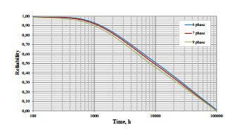
Figure 11: Reliability function of a CHB inverter.
On the basis of the schedule of acceptable in-verter’s overload (see Figure 4) and the method de-scribed in [24], the qualitative analysis of the in-verter’s ability to function was carried out in case of a failure of 1, 2, and 3 submodules in a single phase. The analysis results are summarized in Table 5 and Table 6.
Considering the requirements of the project, the most critical failure mode of the traction drive, as can be seen from Table 5, is when it is necessary to main-tain stably during 2 minutes 113% of nominal power. Further, this mode will be more carefully simulated and estimated for the failure cases using a Markov model.
| 5 Multi-State System Reliability | |
| Markov Model |
For the maximum accurate estimation of the fault tol-erance value of each comparable inverter option and its compliance (or non-compliance) with design re-quirements, a Multi-State System Reliability Markov Model (MSS MM) was constructed, which theoretical base is described in [25, 26].
5.1 State Diagram of Markov Model
For the present study the phase open-circuit failure has been considered as the main dangerous failure for electric inverter, i.e. it is the most severe kind of fail-ure, to which less dangerous failures can be summa-rized. The impact of this failure on the safety operation of the power drive is very significant. In this way, the phase open-circuit failure of a multilevel in-verter’s submodule can be considered as one of the main causes of failures in traction electric drives, since practically all other electrical failures of the inverter can be attributed to it [7].
Thus, the multilevel inverter can be considered as a multi-state system with a loaded functional redun-dancy and consequently, with an appropriate reserve of the fault tolerance. A more accurate approach to build the Markov model is described in [2, 27].
The number of the degraded states of the MSS MM has to be determined in accordance with the require-ments of the project on the fault tolerance and on the technical capabilities of the object to continue func-tioning with reduced performance as a result of the critical failure.
Regarding the above requirements on the fault tolerance of safety-critical drives, as well as statis-tical data on the reliability of electric inverters, it was determined that the optimal model for the anal-ysis of fault tolerance in such conditions is a multi-state Markov model with a minimum of five states, as shown in Figure 12. With one degradative state of in-verter, it is not feasible to realize the required values of fault tolerance.
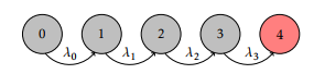
Figure 12: State diagram of MSS MM for a not re-pairable system.
The first state ”0” corresponds to a completely failure-free operation of the inverter. The second, third, and fourth state are the states of degradation and correspond to failure cases. The last red state of the model corresponds to the failure of one phase considering the CHB (see Table 6) or respectively, a completely failed conventional inverter (see Table 5) when the traction motor does not receive the neces-sary power for a safe flight. Thus, every following state of the degradation corresponds to the worst case – a loss of an inverter’s submodule in the same phase.
Table 1: Parameter of the system.
| Parameter | Value | Unit |
| Machine nominal power P | 510 | kW |
| VL1min . . . VL1nom . . . VL1max | 353 …565 …636 | V |
| Vcellmin . . . Vcellnom . . . Vcellmax | 1.4 …2.2 …2.5 | V |
| Battery rack structure | 360s | |
| Vrackmin . . . Vracknom . . . Vrackmax | 500 …800 …900 | V |
| Battery module structure (1 of 24) | 32s | |
| Vmodmin . . . Vmodnom . . . Vmodmax | 44.8 …70.4 …80 | V |
Table 2: Comparison of the data of the B6-bridge and CHB inverter.
| Topology | B6-bridge | CHB – three phase |
| Power | 36 kW | 36 kW |
| Weight | 31 kg | 14.3 kg |
| Volume | 30.8 l | 8.08 l |
| Power-to-weight ratio | 1.16 kW/kg | 2.52 kW/kg |
| Power-to-volume ratio | 1.17 kW/l | 4.45 kW/l |
| efficiency | meas. 95 % | meas. 99 % |
Table 3: Failure rates of inverter components.
| Components | MOSFET | Diode | Capacitor | PCB | CU |
| Failure rate, FIT | 250 | 100 | 80 | 200 | 1000 |
Table 4: Multilevel inverter and number of components.
| Components | MOSFET | Diode | Capacitor | PCB | CU |
| Phase number | |||||
| 6 | 192 | 192 | 48 | 48 | 1 |
| 7 | 224 | 224 | 56 | 56 | 1 |
| 9 | 288 | 288 | 72 | 72 | 1 |
Table 5: Comparison of overload value in failure cases for the conventional B6-bridge.
| Phase number | 6 | 7 | 9 | ||||||||
| Fault number | 1 | 2 | 3 | 1 | 2 | 3 | 1 | 2 | 3 | ||
| Load level | |||||||||||
| 113 % | + | MF | MF | ++ | + | MF | + + + | + + + | ++ | ||
| 85 % | + + + | + | MF | +++ +++ | + | +++ +++ +++ | |||||
| 65 % | +++ +++ MF | +++ +++ +++ | +++ +++ +++ | ||||||||
| + + + 0–10 %; ++ 10–25 %; | + 25–40 % overload; | MF – motor failure | |||||||||
Table 6: Comparison of overload value in failure cases for the CHB.
| Phase number | 6 | 7 | 9 | ||||||
| Fault number | 1 | 2 | 3 | 1 | 2 | 3 | 1 | 2 | 3 |
| Load level | |||||||||
| 113 % | + | PhF | PhF | ++ | + | PhF | + + + | + + + | ++ |
| 85 % | +++ ++ | + | +++ +++ ++ | +++ +++ +++ | |||||
| 65 % | +++ +++ +++ | +++ +++ +++ | +++ +++ +++ | ||||||
| +++ 0–10%; | ++ 10–25 %; + 25–40 % overload; PhF – phase failure | ||||||||
5.2 Transition Probabilities
The most important and difficult fact for a simulation by Markov models is to determine the transition prob-abilities and determination of the number of states with a reduced level of functionality.
The values of the Markov Model transition proba-bilities 1, 2, . . . , k are derived from the results of calculations of the Degree of Fault Tolerance (DOFT ) for the states 1, 2, . . . , k, respectively, according to the method [28] based on the analysis of an overload ca-pacity and thermal stability of an inverter:
| Ri = 1 DOFTRi | (3) |
Here R is the value of reduced level of perfor-mance according to the project requirements and i is the number of critical failures. A large number of dif-ferent factors affect the magnitude of the transition probabilities, from the environmental parameters to the used maintenance strategies, monitoring, and di-agnostics.
As can be seen from (3), for the calculation of the transition probabilities the main challenge is the cor-rect calculation of DOFT for given project required performance levels. The method of determining its value in accordance with [24] is presented below.
Considering the definition of fault tolerance of a technical system as an ability to maintain the required functional level of the system, in case of one or more failures of its components, the DOFT can be defined as the amount of time, in which the system may re-main in a degraded state without irreversible changes in its functionality. Mathematically, in general form this can be written as in (4):
| DOFTRi = | WR | ti | (4) | ||
| WN | tN | ||||
where WR and WN are the reduced (R) and nomi-nal (N) values of the performance of technical system; ti and tN are the duration of functioning after i fail-ures and without failure, respectively.
For quantitative assessment of the overload capa-bility and thermal stability of the inverter’s submod-ule, their thermal behavior for various load modes has been experimentally investigated and is discussed be-low.
5.3 Thermal Behavior of the Inverter
The thermal stability and overload capacity of the power electronic inverter is an important part for a save and sustainable operation of an electrical heli-copter. Therefore, the definition of these parameters must be performed with the great accuracy.
On the basis of an experimental study, the compli-ance of the graph of Figure 4 with the real values of the inverter’s overload capacity was verified, as well as the legitimacy (or illegitimacy) of its use in deter-mining the transition probabilities for MSS reliability Markov Models.
As mentioned above the optimal option, consider-ing the project requirements is a cascaded H-bridge 17-level inverter as shown in Figure 13. It consists of 8 submodules in each phase and 9 similar phases. Each submodule consists of a battery storage unit and a MOSFET full bridge and is connected in series with other submodules.
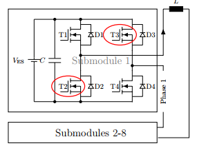
Figure 13: Multilevel CHB inverter submodule.
A full bridge used in a cascaded H-bridge multi-level inverter with lithium batteries was taken into account for an experimental verification of the norma-tive thermal stability of the MOSFET’s power inverter.
For this verification of EN61000-2-4 [29] was the full bridge tested for 20 min with 10% more current than the nominal current, 10 min with 25%, 60s with 50% more current and 1 s with 100% (double of the nominal current). Furthermore the thermal capacity of the inverter has been estimated and the thermal be-havior of the full bridge was observed.
Table 7 shows the characteristics of the MOSFET type IPP023NE7N3, which has been investigated.
Figure 14 shows an experimental test bench for in-vestigating the thermal behavior of the inverter’s sub-module. For the construction of the test bench, the re-sults of the research, discussed in [30–32], were taken into account.
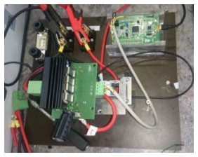
Figure 14: Test bench setup for the thermal tests of the full bridge.
Table 7: Description of the used MOSFET.
| Type | IPP023NE7N3 |
| Maximum voltage | 75 V |
| On-state resistance | 2.3 m |
| Maximum continuous drain current | 120 A |
supply, the submodule, load resistors, and the mea-surement devices. The submodule is directly con-nected to the power supply on the DC-side and the resistors on the AC-side. The DC current at the power supply was set by adjusting the resistance of the load resistors. Therefore the power supply was working in control voltage mode, excepted from the last test (double nominal current), which would exceed the ca-pabilities of the power supply.
The output voltage of the power supply had to be reduced in order not to exceed the maximum output power of 3 kW. The full bridge was working with a pulse width modulated (PWM) signal. The constant pulse width of 500 s was generated by a PWM fre-quency of 1 kHz and a duty cycle of 50%. The sub-module had to operate covered under a box with just a few holes near the top and bottom side. This box en-sures that only natural convection can take place and a possible airflow in the measurement environment would not affect the measurement results.
The measurement data consists out of the time-stamps and two MOSFET temperatures, namely MOS-FET 2 and MOSFET 3 of the submodule from Fig-ure 13. The temperature measurements of the test item, as can be seen in Figure 15, were taken by a ther-mocouple sensor. Two bimetal temperature sensors, which were evaluated by multi-meters, were used as measuring means. Thermal imaging was also used to validate the temperature measurement by the ther-mocouple. The measurement was evaluated as repre-sentative.
Figure 16 shows the picture of the thermal imag-ing camera. It illustrates that the heat transfer to the cooling elements work properly and that the chosen measurement points offer a representative result. A STM32F4 controller generates the PWM signal for the control of the full-bridge. The standard PWM fre-quency within the inverter is 1 kHz. It should be noted that each experiment with different load levels continued until the failure of the tested MOSFETs or when the normative values of the duration of fail-safe operation were significantly exceeded.
The Figures 17–21 show the thermal character-istics of the submodule for various load modes, i.e. nominal load, 10%, 25%, 50%, and 100% overload of power electronic devices. The experiments were stopped when the time range significantly exceeded the normative values of Figure 4 for every load mode. The experimental targets were clearly exceeded. The tested submodule has shown large reserves in the overload capacity. During the tests no unexpected de-fects have been occurred. Thus, the normative over-load data (Figure 4) can be used to determine the tran-sition probabilities of MSS MM without any restric-tions.
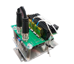
Figure 15: Test item for thermal measurement with measurement points on MOSFET 2 and 3.
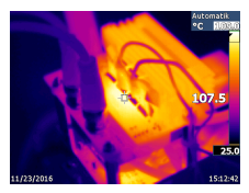
Figure 16: Resulting picture of thermal imaging cam-era.
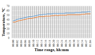
Figure 17: Thermal characteristic for nominal mode without overload.
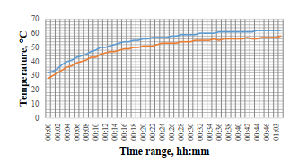
Figure 18: Thermal characteristic for 10% overload.
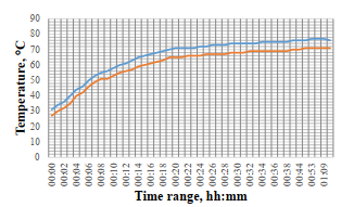
Figure 19: Thermal characteristic for 25% overload.
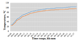
Figure 20: Thermal characteristic for 50% overload.
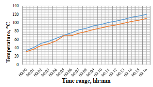
Figure 21: Thermal characteristic for 100% overload.
6. Results of Simulation
By the simulation has been considered the worst case, critically dangerous variant of failure – the submod-ule failures occur consistently in the same phase. In case of the simulation of a not safety-critical fail-ure, as well as the possibility of partial recovery of power drive’s operating ability in the degraded state, the value of the fault tolerance will be significantly higher. Considering the design requirements on the fault tolerance, the sustainable functionality of the inverter in the failure cases was analyzed using the above MSS MM for a power demand of 113% of the nominal value. The corresponding graphs for a differ-ent number of phases are presented in Figure 17.
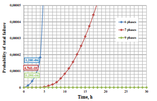
Figure 22: Probability of total failure one inverter phase.
The results of simulation of three consecutive crit-ically dangerous failures allow quantifying the degree of fault tolerance of a multilevel inverter, which is a one important part of the traction drive of helicopters. The 7- and 9-phase options have shown the maxi-mum compliance with the requirements relating to the safety-critical drives. For further studies of re-liability and fault tolerance of safety-critical electri-cal drives, it is advisable to evaluate the integrated performance of electric drive as a whole, considering the reliability characteristics of electric power source, power electronics, and electric motor.
It is also of significant interest to quantitatively as-sess the impact of the maintenance strategy on the re-liability and fault tolerance of electrical drive of the helicopter.
7 Conclusion
The paper presents the results of complex compara-tive analysis of an important part of the safety-critical drive train – the electric inverter, including an analy-sis of the reliability and fault tolerance of inverter in emergency operational modes.
On the basis of the developed techniques and models, taking into account the strict requirements on the safety-critical drive of an electrical helicopter, the authors carried out a comparative analysis of the fault tolerance degree of considered inverter topolo-gies, which, in turn, led to the conclusion about the optimal range of applicability and feasibility of each compared variant of topology considering the speci-fied safety requirements.
- I. Bolvashenkov, J. Kammermann, T. Lahlou, and H.-G. Herzog, “Comparison and Choice of a Fault Tolerant Inverter Topology for the Traction Drive of an Electrical Helicopter”, 3rd Int. Conf. on Electrical Systems for Aircraft, Railway, Ship Propulsion, and Road Vehicles (ESARS16), 02–04 November 2016, Toulouse, France, pp.1–6.
- I. Bolvashenkov, J. Kammermann, S. Willerich, and H.-G. Herzog, “Comparative Study of Reliability and Fault Tolerance of Multi-Phase Permanent Magnet Synchronous Motors for Safety-Critical Drive Trains”, in Proc. of International Conference on Renewable Energies and Power Quality (ICREPQ16), 04–06 May 2016, Madrid, Spain, pp.1–6.
- H. Wang, K. Ma, F. Blaabjerg, “Design for Reliability of Power Electronic Systems”, in Proc. Of the 38th Annual Conference of the IEEE Industrial Electronics Society (IECON12), 25–28 October 2012, Montreal, Canada, pp.33-44.
- E. Lauger, “Reliability in electrical and electronic components and systems”, North-Holland Publishing Co., Amsterdam, 1982, p.1171.
- D. Kastha, B. K. Bose, “Investigation of fault modes of voltage-fed inverter system for induction motor drive”, IEEE Transactions on Industry Applications, Vol.30, No.4, Jul/Aug 1994, pp.1028–1038.
- B. A. Welchko, T. A. Lipo, T. M. Jahns and S. E. Schulz, “Fault Tolerant Three-Phase AC Motor Drive Topologies: A Comparison of Features, Cost, and Limitations”, IEEE Transactions on Power Electronics, Vol.19, No.4, July 2004, pp.1108-1116.
- I. Bolvashenkov and H.-G. Herzog, “Approach to Predictive Evaluation of the Reliability of Electric Drive Train Based on a Stochastic Model”, 5th International Conference on Clean Electric Power (ICCEP15), 16–18 June 2015, Taormina, Italy, pp.1–7.
- R. Bojoi, M.G. Neacsu and A. Tenconi, “Analysis and Survey of Multi-Phase Power Electronic Converter Topologies for the More Electric Aircraft Applications”, In Proc. of International Symposium on Power Electronics, Electrical Drives, Automation and Motion (SPEEDAM), 20–22 June 2012, Sorrento, Italy, pp.440–445.
- A. L. Julian and G. Oriti, “A Comparison of Redundant Inverter Topologies to Improve Voltage Source Inverter Reliability”, IEEE Transactions on Industry Applications, Vol.43, No.5, Sept./Oct. 2007, pp.1371–1378.
- Y. Ding, P. C. Loh, K. K. Tan, P. Wang, and F. Gao, “Reliability Evaluation of Three-Level Inverters”, In Proc. of IEEE Twenty-Fifth Applied Power Electronics Conference (APEC), 21–25 Feb. 2010, Palm Springs, CA, USA, pp.1555–1560.
- D. Fodorean, M. Ruba, L. Szabo, A. Miraoui, “Comparison of the main types of fault-tolerant electrical drives used in vehicle applications”, In Proc. of International Symposium on Power Electronics, Electrical Drives, Automation and Motion, (SPEEDAM), 11–13 June 2008, Ischia, Italy, pp.895–900.
- M. Villani, M. Tursini, G. Fabri and L. Castellini, “Multi-Phase Permanent Magnet Motor Drives for Fault-Tolerant Applications”, In Proc. of IEEE International Electric Machines & Drives Conference (IEMDC), 05 18 May 2011, Niagara Falls, Canada, pp.1351–1356.
- J. Kammermann, I. Bolvashenkov and H.-G. Herzog, “Approach for Comparative Analysis of Electric Traction Machines”, In Proc. of 3rd International Conference on Electrical Systems for Aircraft, Railway, Ship Propulsion, and Road Vehicles (ESARS) Aachen, Germany, March 2015, pp.1–5.
- M. Malinowski, K. Gopakumar, J. Rodriguez, and M. Perez, “A Survey on Cascaded Multilevel Inverters”, IEEE Transaction on Industrial Electronics, Vol. 57, No. 7, July 2010, pp.2197–2206.
- B. Sarrazin, N. Rouger, J. P Ferrieux, J. C Crebier, “Cascaded Inverters for electric vehicles: Towards a better management of traction chain from the battery to the motor?”, In Proc. of IEEE International Symposium on Industrial Electronics, 27-30 June 2011, Gdansk, Poland, pp.153–158.
- S. Fazel, S. Bernet, D. Krug, K. Jalili, “Design and Comparison of 4-kV Neutral-Point-Clamped, Flying-Capacitor, and Series-Connected H-Bridge Multilevel Converters”, IEEE Transactions on Industry Applications, Vol.43, No.4, July/Aug. 2007, pp.1032–1040.
- O. Josefsson, T. Thiringer, S. Lundmark, H. Zelaya, “Evaluation and comparison of a two-level and a multilevel inverter for an EV using a modulized battery topology”, In Proc.of IEEE 38th Annual Conference on Industrial Electronics Society (IECON), 25–28 Oct. 2012, Montreal, Canada, pp.2949–2956.
- N. P. Ermolin and I. P. Zerichin, “Zuverlssigkeit elektrischer Maschinen”, Berlin, Verlag Technik, 1981, p.227. (in German)
- M. Molaei, H. Oraee and M. Fotuhi-Firuzabad, “Markov Model of Drive-Motor Systems for Reliability Calculation”, In Proc. of IEEE International Symposium on Industrial Electronics, 09–13 July 2006, Montreal, Canada, pp.2286–2291
- T. Geyer and S. Schroder, “Reliability Considerations and Fault-Handling Strategies for MultiMW Modular Drive Systems”, IEEE Transactions on Industry Applications, Vol.46, No.6, Nov./Dec. 2010, pp.2442–2451.
- P. Wikstrom, L. A. Terens and H. Kobi, “Reliability, Availability, and Maintainability of High-Power Variable-Speed Drive Systems”, IEEE Transactions on Industry Applications, Vol.36, No.1, Jan./Feb. 2000, pp.231–241.
- A. H. Ranjbar, M. Kiani and B. Fahimi, ”Dynamic Markov Model for Reliability Evaluation of Power Electronic Systems”, In Proc. of IEEE International Conference on Power Engineering, Energy and Electrical Drives (POWERENG), May 2011, Malaga, Spain, pp.1–6.
- Y. Song and B. Wang, “Survey on Reliability of Power Electronic Systems”, IEEE Transactions on Power Electronics, Vol.28, No.1, January 2013, pp.591–604.
- I. Bolvashenkov and H.-G. Herzog, “Degree of fault tolerance of the multi-phase traction electric motors: methodology and application”, In Proc. Of 16th IEEE International Conference on Environment and Electrical Engineering (EEEIC), 07–10 June 2016, Florence, Italy, pp.1–6.
- B. Natvig, “Multi-state systems reliability theory with applications”, John Wiley & Sons, New York, 2011, p.232.
- A. Lisnianski, I. Frenkel and Y. Ding, “Multistate System Reliability Analysis and Optimization for Engineers and Industrial Managers”, Berlin, New York, Springer, 2010, p.393 p.
- I. Bolvashenkov, J. Kammermann, and H.-G. Herzog, ”Reliability Assessment of a Fault Tolerant Propulsion System for an Electrical Helicopter”, Proceedings of 12th International Conference and Exhibition on Ecological Vehicles and Renewable Energies (EVER), 11–13 April 2017, Monaco, pp. 1–6.
- I. Bolvashenkov, J. Kammermann, and H.-G. Herzog, ”Methodology for determining the transition probabilities for multi-state system Markov models of fault tolerant electric vehicles”, In Proc. of Asian Conference on Energy, Power and Transportation Electrification (ACEPT), 25–27 Oct. 2016, Singapore, pp.1–6.
- EN61000-2-4, https://www.vdeverlag.de/normen/0839015/din-en-61000-2-4-vde-0839-2-4-2003-05.html, visited on 01.09.2016.
- C. D. Tudryn, B. Blalock, G. Burke et al., “Low Temperature Thermal Cycle Survivability and Reliability Study for Brushless Motor Drive Electronics”, In Proc. Of IEEE Aerospace Conference, 04–11 March 2006, Big Sky, MT, USA, pp.1–37.
- Z. Zhao, K. Li, Y. Jiang, S. Lu, and L. Yuan, “Overview on Reliability of Modular Multilevel Cascade Converters”, In Chinese Journal of Electrical Engineering, Vol.1, No.1, December 2015, pp.37–49.
- I. Vernica, K. Ma and F.Blaabjerg, “Modelling and Improvement of Thermal Cycling in Power Electronics for Motor Drive Applications”, In Proc. of IEEE Energy Conversion Congress and Exposition (ECCE), 18–22 Sept. 2016, Milwaukee, WI, USA, 2016, pp.1–8.