Magnetically Levitated and Guided Systems
Magnetically Levitated and Guided Systems
Volume 2, Issue 3, Page No 241-244, 2017
Author’s Name: Florian Pucia), Miroslav Husak
View Affiliations
Department of Microelectronics, FEE CTU in Prague, 166 27, Czech Republic
a)Author to whom correspondence should be addressed. E-mail: puciflor@fel.cvut.cz
Adv. Sci. Technol. Eng. Syst. J. 2(3), 241-244 (2017); ![]() DOI: 10.25046/aj020333
DOI: 10.25046/aj020333
Keywords: magnetic levitation technology, planar micro-actuator, Stator, translator

Export Citations
The paper describes the fundamentals of magnetic levitation technology. A general background of the magnetic levitation is given in this article, including applications of this technology, several comparisons with other types of technologies, the real stage of its development, etc. Further in the paper, the two main types of magnetically levitated systems are compared within their subgroups, on characteristics and specifications basis. A comparison between the AC and DC power supplies for these systems, including the pros and cons of each type, is also provided in the paper.
Received: 29 March 2017, Accepted: 25 April 2017, Published Online: 02 May 2017
1. Introduction
The up and coming era of lithography requires a high exactness organize, which is perfect with a high vacuum condition and for this, a magnetic levitation stage with two or more degrees-of-freedom is considered state-of-the-art technology innovation. Nowadays the size of wafer is moving up to 12 inch to enhance the efficiency of a batch process. Thusly, a high-resolution process and a large operating range simultaneously with the application into a super-clean condition are the prerequisites for the related smaller scale actuators. The non-contact characteristic of magnetic levitation technology (MAGLEV) empowers high accuracy positioning as well as no particle generation. The assembling procedure of a current semiconductor IC, forces exceptionally extreme requirements on the preparing exactness as well as the workplace. However, the heat is inevitably generated, while using electromagnetic actuators for levitation, which deforms the structures and degrades accuracy of the stage, and though a gravity compensator is required.
Between the parts with relative motion of the new sort of wafer transporters, spoke to for instance by belt transporters or articulated robots, there are mechanical contacts. For the most part, to limit and diminish the friction and enhance smooth operation, lubricants (oils) are used in the contact regions. In any case, because of the rubbing activity, there are constantly created a lot of tiny solid particles which are mainly absorbed by the lubricant. During the production process, it can happen that some particles can still flee the wafer transporter. Eventually, a portion of the particles will drop back onto the surface of wafers, damaging the fragile and newly manufactured integrated circuit (IC) device.
A fully operational system with magnetic levitation technology is strongly required to have the following characteristics:
- Gravity compensation with no power consumption
- Large and homogenous force density
- Zero stiffness between the translator and stator part
- Position-independent dynamic force
- Enough workspace for operation in all directions
In the nowadays microelectronic industry, the wafer transporter is ranked the number one in the list of particle source extrinsic to the fabrication process. The presence of lubricant in the contact regions has a negative impact to the process cleanness and this results from the volatility of lubricant. The surface properties are strongly affected by the migration and the diffusion of the gaseous elements into the surface of wafers.
An answer can be that the rate of evaporation is enhanced by the application of a vacuum environment, since the undesirable gaseous elements are evaporated to the processing environment. Obviously, reduction or if possible total elimination of the contact between relatively moving components, is the most ideal approach to eliminate wafer transport contamination. In this way, a particle-free and oil-free environment can be obtained and consequently both particle generation and lubricant evaporation will disappear simultaneously. For instance, in a wafer transporter, mechanical contacts typically happen and are persistently present in the area between the part that conveys the wafer, so the wafer carrier, and the transporter base that supports the carrier. By isolating the wafer carrier from the transporter base, these mechanical contacts can be dispensed with. This can be accomplished by means of levitation, where non-contact physical forces are applied between the carrier and the base, so the carrier is separated from the transporter base. In the known physical world, there exist three principle strategies that the free-floating levitation can be accomplished:
a) air-bearing
b) electrostatic levitation
c) maglev
To determine the most suitable and effective technique for our application, is required a general physical understanding of each method’s working theory including some fundamental information of incorporated circuit manufacture innovation. An air-bearing system essentially requires two very important components: a special filter used to exclude particles generated by the air pump from entering the transporter and an additional circulation system used to enclose the air. In comparison, with the air-bearing system, in the electrostatic levitation one, the particle residues which are generated in the first installation or accidentally generated during wafer loading and unloading process will be pulled by the electrostatic field. Consequently, this can cause possible particle contamination, with the particles being stick to the transporter due to the electrostatic field.
Given the above contentions and to achieve various performance targets, the precision stage using a novel contact-free planar actuator with magnetic levitation is highly recommended and this paper consider it the best solution for IC manufacture. Generally, as MAGLEV eliminates the friction due to a mechanical contact, it has a variety of applications requiring super-cleanness environment, including here the semiconductor wafer transfer. The way of usefulness and functionality of MAGLEV eliminates the problems caused by using the above technologies. It makes a steady state with no mechanical contact when the gravitational force is solely counterbalanced by magnetic forces. This system incorporates levitating tracks, stabilizing tracks, and propulsion coils [2].
2. Magnetically levitated planar actuators
Different types of conventional transportation systems such belt-type conveyors or articulated robots generate dusts and pollution due to the mechanical friction or lubrication. These systems are inadequate and improper to satisfy the environmental demands. The MAGLEV technology has the advantages of being contact free, eliminates the mechanical components e.g., gears, guide etc., reduces the mechanical alignment and maintenance cost, hence it satisfies the environmental demands. In this manner, research on contact-free type transportation system and actuator has been actively performed by worldwide researchers. Present day applications of this technology in equipment like magnetic bearings and magnetically levitated vehicles have given renewed impetus to research efforts in the direction of electromagnetic levitation [3-4].
There exist two main categories of planar actuators, referred as either with moving coils or moving magnets. The actuators from the first type consist of moving air-core coils and stationary magnets. The main advantage of such system is the usage of a small number of coils and their amplifiers, as the stroke force can be easily increased by adding a few more magnets in the magnet array. Additionally, the simple design of these actuators allows torque control on the translator part by using different coil topologies. A major disadvantage for this configuration is the presence of a cable connecting the translator and the stator part, as the coils require power and cooling. The following Figure 1 shows an example of these planar actuators.
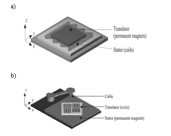
Figure. 1. Planar actuators: a) moving magnets, b) moving coils
The other category is represented by actuators with moving magnets and stationary air-core coils. In opposite with the other class of actuators, it doesn’t require a cable for connecting the translator and stator part, which is a big advantage from the design point of view. With the coils located and powered in the stator platform, the amount of disturbances delivered to the levitated translator is then reduced significantly. On the other hand, the torque decoupling as a function of position is more complex than in the moving-coils planar actuators. During manufacturing process, working environment affects the quality of the precision products [3].
3. Designed planar actuator with moving magnets
The moving coil principle in microstructure designs requires powering and cooling of the coils. Additionally, including here the guidance of the current lines on the thin etched silicon beams. The springs which are driven by the Lorentz force, are moving in the magnetic field generated by an external magnet. Strong currents are required to produce large deflections, though this can cause thermally induced bending or buckling of the thin microstructures. Hence, the principle with a moving magnet is more effective, including less complex circuit design.
The carrier consists of several permanent magnets and essentially its stabilization is required. Ideal case is a uniform object with the center of mass coincident with the center of geometry. In numerical analysis, the magnetic flux is firmly related with the levitation distance between the levitated magnet and the cylindrical solenoid underneath. If such distance is very small, then the magnetic flux approaches a constant value. The aim of the stator configuration is the arrangement of the cylindrical solenoids and their floating currents in such a way, so together would form a uniform magnetic field over a planar surface slightly above the coil array. The high-precision positioning performance requires proper setup of carrier control and levitation height. The Figure 2 shows an example of a planar actuator with moving magnets.
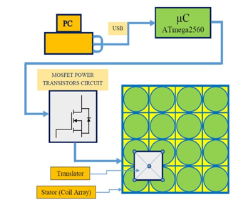
Figure 2. Block diagram of the planar actuator with moving magnets
Referring to the type of planar actuator described here, the translator is represented by a uniform shaped object with specific characteristics. This is embedded with one stabilizing permanent magnet on each corner so it can give sufficient control force against the lateral forces, and with one permanent magnet on the bottom of the carrier to counteract the weight of the carrier. For achieving a high-precision positioning performance, it is required to set up properly the control and the height of the carrier. Coils are supplied by the current flowing through Arduino board pins which are connected to the circuits consisting of MOSFET power transistors. In order to increase the output current from the board pins and strengthen the magnetic field around the coil, 4 such circuits with power MOSFET transistors were designed. For full control of the floating current of the coils, four such circuits are needed. In the stator platform, there are located 16 identical coils, forming together a 4×4 array. The current flowing through a relevant coil is controlled from the output Pulse-Width-Modulation (PWM) signal of one of the board pins of Arduino Mega 2560 [5].
The table below shows the accomplished parameters of the designed microactuator with moving magnets.
| Parameter | Value | Unit | ||
| min | typical | max | ||
| Supply voltage range | 12 | – | 20 | V |
| Height of magnetically levitated translator | – | 5 | – | mm |
| Coil’s current | – | 0.5 | – | A |
| Electromagnetic field strength | – | 62 | – | μT |
| Coil’s resistance | – | 4.9 | – | Ω |
Table. Microactuator overall parameters
4. Supply sources for MAGLEV systems
There exist two main approaches for designing a controlled force magnetic levitation system: the first one uses the attractive forces between an electromagnet and a magnetic flux closure, and the other is based on repulsive forces in interaction between electromagnets and permanent magnets.
Electromagnetic levitation technology uses either an Alternative Current (AC) or Direct Current (DC) source to drive the electromagnets. Despite the fact that there have been manufactured and tested several experimental frameworks which use as the supply an AC source, this method for adjustment is fitting for applications where mass of the levitated object is relatively small. The AC method of stabilization is inappropriate for heavy payloads due to the losses caused by the effect of the eddy currents, the complex circuit design and control of power modulation.
Conversely with the above AC method, the DC method, known also as the electromagnetic levitation system (EMLS), is characterized by simpler circuit configuration and favorable power requirement. The DC EMLS circuits use a switched mode power amplifier to control and utilize the current as well as the attraction force of the electromagnets. An electromagnetic levitation system consists of four main components: (i) Actuator and Rail, (ii) Position Sensor, (iii) Controller, (iv) Power amplifier [6].
The electrodynamic system utilizes the repulsive forces to levitate the carrier, conversely with the other system which levitates the carrier based on the attractive forces. The gap between the magnet pole-face and the ferromagnetic object is sensed and measured by a position transducer. The output signal from the transducer is fed back to a comparator and the process continues with output signal of the comparator being applied to a position controller, giving in this way the reference current for the current loop. The current sensor compares the actual current supplying the coil with the reference current. The power amplifier, a major component in this configuration, produces necessary currents in the actuator coils after receiving a command from the current controller. Preceding this, the current controller completes the current error process task. The output currents from the power amplifier are used to supply the coils. These generate requisite magnetic forces which are the key for levitating the translator.
Applications of electromagnetic levitated and guided systems, can be found for example, in the field of transportation vehicles, frictionless bearings, conveyor systems and lithography scanners [6].
Conflict of Interest
The authors declare no conflict of interest.
Acknowledgment
Research described in the paper was supervised by Prof. Ing. Miroslav Husak, CSc., FEE CTU in Prague and has been supported by the CTU project No. SGS14/195/OHK3/3T/13 “Development of Smart Devices and Systems in the Field of Microelectronics, Nanoelectronics, Optoelectronics and Micro-nano-optoelectronic structures, elements and systems”.
- Y. M. Choi, M. G. Lee, D. G. Gweon, J. Jeong, “A new magnetic bearing using Halbach magnet arrays for a magnetic levitation stage”, Rev. Sci. Instrum., 80 (4), 1-9, 2009.
- H. Park, S. K. Lee, J. H. Yi, S. H. Kim, Y. K. Kwak, I. A. Wang, “Contactless magnetically levitated silicon wafer transport system”, J. Mech., 6 (5), 591-610, 1999.
- C. M. M. van Lierop, “Magnetically levitated planar actuator with moving magnets: Dynamics, commutation and control design”, Ph.D Thesis, Eindhoven University of Technology, 2008.
- J. W. Jansen, “Magnetically levitated planar actuator with moving magnets: Electromechanical analysis and design”, Ph.D Thesis, Eindhoven University of Technology, 2007.
- F. Puci, M. Husák, “Translator with Magnetic Levitation” in 10th International Conference on Advanced Semiconductor Devices and Microsystems, Bratislava, 2014.
- P. K. Biswasa, S. Banerjeeb, “Design and ANSYS Software Based Simulation of U-I Type Actuator and Rail Used in Electromagnetic Levitation System”, Int. J. Appl. S. Eng., 12 (3), 225-239, 2014.