Enabling Toy Vehicles Interaction With Visible Light Communication (VLC)

Adv. Sci. Technol. Eng. Syst. J. 2(3), 210–216 (2017);
 DOI: 10.25046/aj020328
An effective communication among the road users is crucial for safety precautions. Nowadays, a light emitting diode (LED) are commonly installed on a motor vehicle as the lighting system. The LED lights are more reliable and flexible in terms of the design and power adjustments. To further utilize the LED applications in a vehicular system, a simple data transmission system based on LED lights for short distance is developed. Toy vehicles are used to demonstrate the functionality of the system. This paper explains the components used and the communication protocols of A and B that have been developed and tested. The implementations of a software-based modulation and communication protocols by using a microcontroller can be considered as the initial approach that can be further enhanced for future development. In this paper, the prototype of the system as well as the experimental results are presented. The prototypes are able to send short messages by using the LED and photodetector (PD) which could reach up to 2-meter distance. In addition, it is also believed that this project can be implemented on the real motor vehicles subject to a few improvements.
1. Introduction
This paper is an extension of the work originally presented in 2016 IEEE Student Conference on Research and Development (SCOReD) [1]. The previous work focused on the development of communication protocol and data transmission performance of the toy vehicle VLC system. On the other hand, this work presents the application and prototype of the toy vehicle interaction protocol that have been mentioned in the previous paper.
This work is inspired from one situation that involves a multiple road users. The situation occurs in the middle of the night, on a single lane road, where the driver of a car needs to overtake a slow truck. However, due to the size of the truck, the car’s driver is not able to see the traffic from the other side of the road without slightly moving to the opposite lane which is dangerous and might be fatal. Therefore, in order to have a safer driving experience, standard vehicles such as cars and trucks must have several signalling devices such as indicators, brake light, hazard warning lights, headlights and reverse lights [2]. However, the current technology can only provide a limited number of signalling signs such as turning left or right, brake signal, reverse signal, and hazard warning signal.
In the year 2012, the car manufacturer, i.e.: Volvo, started to build a system that enables the communication of a car-to-car and car-to-medium. These types of communication ensures safer driving experience. The technology relies on the GPS system and a dedicated wireless network, in which the car-to-car communication has already acquired a separate range of radio frequency for that purpose. Vehicles within a given radius would be automatically linked together and able to exchange information such as the position, speed, and direction [2,3].
Nowadays, the radio frequency spectrum is highly congested due to the demand for wireless communication applications [3]. As a natural source of energy, a visible light can be thought as an alternative to the RF communication. The visible light communication (VLC) possesses a few key advantages over the wireless RF transmitters. It has a nearly infinite bandwidth, free and unregulated channels, poses no health hazards and concerns, and consumes much less power per given transmission [4,5]. VLC is also a potential low-power and low-cost alternative to the traditional short-range wireless RF communications [6-8].
In this work, a data transmission system for two toy vehicles has been developed by using a light emitting diode (LED) which is highly reliable for short distance communication. It has also been demonstrated that the current LED signalling technology can be further utilized by using the VLC. The LED provides a visual indicator as well as a communication channel for both vehicles to exchange information. Additionally, it provides a medium for the front toy vehicle to convey any information efficiently to the rear toy vehicle.
This paper is organized as follows: Section 2 introduces the design method for the VLC system which is followed by Section 3 that discusses the results and discussion. Finally, the paper is concluded in Section 4.
2. Visible Light Communication (VLC) Design
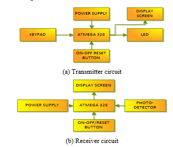
This section focusses on the VLC circuit development starting from the LED selection until the successful implementation of communication between the LED and photodetector (PD). As shown in Fig.1, the transmitter circuit consists of a keypad, LED, and display screen. On the other hand, the receiver circuit only has a PD and display screen. Both circuits have a common microcontroller which is known as Atmega328. It is the brain of the circuit and is responsible for all operations that include the modulation, signal processing and keypad response. When the keypad is pressed, the microcontroller gives an order to the LED to transmit a signal. The data are transmitted using on-off keying modulation (OOK). At the receiver, the PD will detect the signal which will then trigger the microcontroller to demodulate the transmitted signal as well as activating the display screen to show the message.
2.1. Optical hardware selection
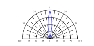
In order to establish the VLC communication, an appropriate LED and PD selection must be performed. In this work, the choice of LED must take into account the cost, efficiency, and performance. The LED model chosen in this work is COM-00531. It is classified as a super bright LED and emits white colour. The LED viewing angle is very narrow at 10°, as can be seen from the specification in Table 1 and further illustrates in Fig. 1. The narrow angle will lead to a more focused beam of light that provides better detection. In addition, its emission spectrum is very wide, ranging from 400 nm to 800 nm.
Table 1: Specifications of COM-00531 LED
| Material of construction | InGaN/GaN |
| Emitted colour | White |
| Lens color | Water clear |
| Viewing angle | 10o |
| Typical luminous intensity at 20mA | 10cd |
| Typical forward voltage at 20 to 30mA | 3.5V |
| Reverse Current | 10 uA |
As for the PD, a 5-mm PD (flat head) is selected as the light sensor for this work. Table 2 shows the specification of the PD. The justification of this selection is that the PD could detect a light from 400 nm to 1100 nm that covers the visible light range of wavelengths. In addition, it also has a high reverse voltage that could be used to alter the sensitivity of the photo detection for higher detection performance.
Table 2: Specifications of 5-mm PD (flat head)
| Reverse voltage | 35V |
| Power dissipation | 50mW |
| The peak wavelength sensor | 940nm |
| Spectral bandwidth | 400 – 1100nm |
| Reverse light current | 40uA |
A few experimental procedures have been conducted to evaluate the performance of the LED and PD. An oscilloscope is used to observe the behavior and functionality of the LED and PD. The main objective of these experiments is to determine the maximum rate of data transmission for the LED-PD pair. By comparing the signal generated by the PD to the signal provided by the LED, a performance analysis can be examined.
2.2. Electrical Domain
In this section, the VLC design process in an electrical domain is discussed which consists of OOK modulation, communication protocol and system integration.
2.2.1 On-Off Keying (OOK) Modulation
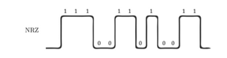
In this work, a non-return-to-zero on-off-keying (NRZ-OOK) with direct detection (DD) is used for modulation as shown in Fig. 3. From the figure, Signal 1 is represented by 5 V and Signal 0 by 0 V, respectively. The PD is continuously detecting the data by using a time delay method that samples the data continuously for every period of time. The modulation is implemented in a software level on the microcontroller as to ease the design process.
In this experiment, the possibility of sending signals between the LED and PD is verified. Furthermore, the maximum possible speed of operation for a certain communication distance is investigated. The programming code for this experiment has the following roles:
- To receive the binary input signal from the user’s computer (convert the ASCII characters to binary data) – in the transmitter.
- To send data by using an OOK modulation.
- To detect these signals by using a PD.
- To demodulate the message and recover the original binary string.
Once the programming code has been developed and uploaded to each circuit, the experiment is conducted by placing the transmitter and the receiver at a separation distance of 1 cm and 5 cm. Initially, to test the system, a time delay of 1000 milliseconds (ms) is setup for the delay function. Depending of the successful achievement of the experiment, the delay time is then shortened accordingly. For a start, a random binary string is chosen: 01010101 (ASCII: ‘U’). If the serial monitor’s output produced the same binary string, the experiment can be considered as successful. The experiment setup with the programming code consists of a LED as the transmitter and a PD in the receiver. A binary data sent by the transmitter should be displayed on the receiver.
2.2.2 LED-PD Communication: The Setup of Communication Protocol
This section discusses the setup of communication protocol in the communication system namely, Protocol A and B.
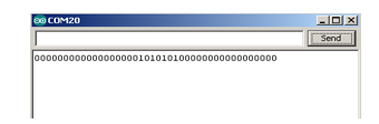
In the previous experiment, the binary string of 01010101 is not the only signal received as the receiver cannot distinguish whether the signal is an actual data or a noise. The serial monitor’s output can be viewed Fig. 4. In order to solve this problem, a communication protocol must be established.
Since the objective is to develop a working interactive communication between the two toy vehicles by using a LED signalling, the needs to convert the received binary data to a real and readable information is compulsory. Hence, another programming code is written that would have all the existing features from the previous experiment and also the ability to send an actual text.
In order to get the new code working, two additional features need to be added which are:
- The conversion from text to binary – in the transmitter.
- The conversion from binary to text – in the receiver.
2.2.2.1 The Setup of Communication Protocol A
The best way to address the problem is to add another LED for the transmission to provide a synchronous data transfer for both devices. The communication system would now work with the following procedures:
- Once the message has been input on the transmitter’s serial monitor, the LED begins sending the message through OOK.
- If the receiver secondary PD receives any signals from the transmitter secondary LED, it tells the receiver primary PD to start receiving the data sent from the transmitter primary LED.
- Once the transmitter primary LED finishes sending the message, the transmitter secondary LED turns off. Thus, the receiver secondary PD will stop receiving any signals and will tell the receiver primary PD to stop receiving data.
- After conversion is done, it will then be displayed on the monitor.
The hardware experimental setup consists of two LEDs as the transmitter and two PDs in the receiver circuit. The primary LED is used for data transmission while the secondary LED and PD are used to indicate the start and end of a transmission period.
2.2.2.2 The Setup of Communication Protocol B
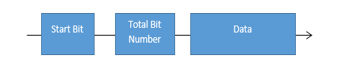
Now that the transmitter needs two LEDs to set up a successful communication to the receiver, it is not practical to be implemented in real life situation because the LEDs need to be placed directly at the opposite of the receiver. Therefore, a new protocol is developed so that only one LED is needed for every data transmission. Fig. 5 shows the protocol that has been implemented in the transmitter and receiver system. Every data transmission begins with a start bit, followed by the information on the total bit number and the actual data packet.
Thus, this experimental setup only comprises of one LED as the transmitter and one PD in the receiver circuit. A string data is sent by the transmitter by using a new protocol and will then be displayed on the receiver.
2.3. VLC Complete Circuit Development
This section focuses on the complete VLC circuit development which consists of a 4 × 4 keypad, 5110 LCD, PD, and LED.
2.3.1 Transmitter Circuit with 4 × 4 Keypad and LCD
In this section, a programming code is written to combine the transmitter circuit with a 4 × 4 keypad. Each button has been assigned to a specific string of characters and it is used as a source of information to be transmitted. When a button is pressed, the string will be displayed on the 5110 LCD before being converted to the binary string by using the ASCII codes. The binary data will then be used for OOK modulation. Table 3 shows the characters that has been assigned to each button.
Table 3: String of characters assigned to each keypad button
| Button | Proposed LED Technology (Visual and Data Transmission) |
| 1 | Turn left |
| 2 | U-turn |
| 3 | Turn right |
| 4 | Thanks |
| 5 | Overtake |
| 6 | Welcome |
| 7 | Emergency |
| 8 | Too bright |
| 9 | Open light |
| B | Fire truck |
| C | Police |
| D | Ambulance |
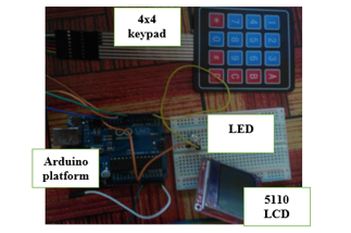
Fig. 6 shows the hardware setup of the experiment which consists of a LED, 5110 LCD, 4 × 4 keypad and Arduino microcontroller as the programming platform.
2.3.2 Receiver circuit with LCD
In this section, the receiver is used to display the received characters on a LCD screen. As the receiver received the characters, it is sent to the LCD to be displayed. There is no predetermined character on the LCD. All the received characters are totally based on the received signals.
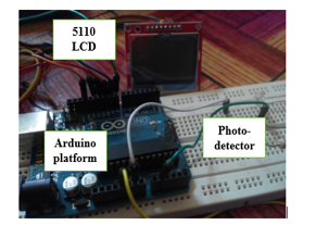
Fig. 7 shows the hardware setup of the experiments which encompasses of a LED, 5110 LCD and Arduino microcontroller as the programming platform. The performance of the combined receiver circuit is evaluated with the combined transmitter circuit.
3. Results and Analysis
In this section, the results in optical domain, electrical domain, and circuit integration of each experiment are presented and analysed.
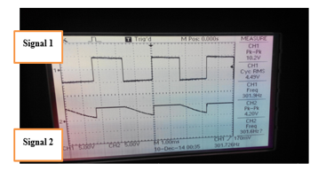
Fig. 8 is the oscilloscope screen that displays the result of the experiment to test the functionality and performance of a PD. Signal 1 is the square signal that is injected into the LED with a function generator. On the other hand, Signal 2 is the behavior of PD in the presence of light from the LED. It is observed that when the LED is having a high voltage that represents bit 1, there is a voltage rise on the PD. Conversely, when there is no voltage on the LED, the voltage at the receiver decreases. However, the rate of voltage falling on the PD is significantly slower as compared to the rate of voltage rising. This indicates the maximum data rate that the photodiode could handle. In the experiment, the frequency used for injecting the signal to the LED is approximately 300 Hz. In order to have a reliable system, the maximum data rate should be lower than 300 Hz so that the fall time of PD is not an issue during data processing.
3.1. Electrical Domain
In this section, the results for electrical domain experiments that cover data modulation and communication protocol are presented and analysed.
3.2.1 OOK Modulation Performance
Table 4 and 5 show the experiment results in Section 2.2.1 that compare the delay time and the status of the received string as the distance is increased from 1 cm to 5 cm. The experiment is conducted to find the limit of data transmission rate that could be handled by the system. The results indicate that the maximum time delay that the transmission could handle is 5 milliseconds. This work does not require a fast data transmission rate, but rather a reliable system. However, the distance covered is not long enough due to the limitation of using only one LED. A LED produces a noncoherent and diverging light output pattern. At greater distances, the intensity of the light are becoming much lower and restricts the receiver LED to receive the data.
Table 4: Results for 1 cm distance
| Delay time (ms) | Status of the received string |
| 1000 | Correct |
| 100 | Correct |
| 10 | Correct |
| 5 | Correct |
| 1 | Wrong |
Table 5: Results for 5 cm distance
| Delay time (ms) | Status of the received string |
| 1000 | Correct |
| 100 | Correct |
| 10 | Correct |
| 5 | Correct |
| 1 | Wrong |
3.2.2 Communication Protocol A and Protocol B
Fig. 9 and Table 6 show the results of the experiments in Section 2.2.2.1 and 2.2.2.2. The experiments are conducted to determine the performance of the communication protocols when implemented on the actual system. Both protocols are developed to enable the receiver to distinguish between the actual data and unwanted data. Therefore, the receiver will only process the transmitted data and ignore the unwanted data. It also helps in synchronizing the transmitter and receiver transmission timing so that an accurate and reliable data transfer could be established. However, only communication Protocol B is used in the final design since it offers more flexibility as compared to Protocol A. Further explanation can be read in [1].
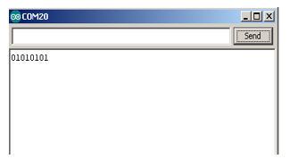
Table 6: Results for communication Protocol A and B
| Character transmitted | Status |
| Turn left | Successfully Received |
| U-turn | Successfully Received |
| Turn right | Successfully Received |
| Thanks | Successfully Received |
| Overtake | Successfully Received |
| Welcome | Successfully Received |
| Emergency | Successfully Received |
| Too bright | Successfully Received |
| Open light | Successfully Received |
| Fire truck | Successfully Received |
| Police | Successfully Received |
| Ambulance | Successfully Received |
3.3. VLC Complete Circuit Integration
In this section, a complete circuit of VLC system is presented. The transmitter and receiver circuits have been successfully developed.
3.3.1 Complete Transmitter Circuit
The transmitter circuit has been successfully combined with a 4 × 4 keypad and 5110 LCD. The keypad is used to initiate the data transmission and the characters are displayed on the 5110 LCD. A minor adjustment is made where the user has to press button A to initiate a transmit mode. The changes are made so that the transmitter is compatible with the receiver circuit when they are combined. The program uses 10,962 bytes (33%) of the program storage space that have a total of 32,256 bytes. On top of that, the global variables use 1,204 bytes (58%) of the dynamic memory, leaving only 844 bytes for local variables. Table 7 shows the results of the transmitter circuit that has been integrated with a 4 × 4 keypad and 5110 LCD.
3.3.2 Complete Receiver Circuit
A combination of the receiver circuit and 5110 LCD has been successfully performed. The receiver circuit will continuously check the condition of PD. If any transmission is detected, the received characters will be displayed on the 5110 LCD. The program uses 10,466 bytes (32%) of the program storage space while the global variables use 1,299 bytes (63%) of the dynamic memory, leaving only 749 bytes for local variables. Notice that the global variable consumes so much dynamic memory which can make the program to be slightly unstable. Some of the original data have to be simplified so that a minimum number of global variables is used. Table 8 shows the results of an integration of the receiver circuit with 5110 LCD.
4. Conclusion and Future Work
In this work, a visible light data communication that can function as a transmitter and receiver has been developed. A LED and PD are used as the light source and light sensor, respectively. In addition, an interactive communication between the two prototype toy vehicles by using a LED signaling has also been constructed in which the transmitter could transmit any characters or information to the receiver by using a single source of light. Currently, the characters that are being assigned to the transmitter are turn left, turn right, U-turn, police indicator, ambulance indicator, and fire truck indicator.
There are, however, a few limitations of this work, which can be attributed from the circuit connections, the written programming code and the platform that is being used. The proposed suggestions are listed below to overcome the limitations which can be considered for future work:
- Faster Processing Platform
A faster processing platform such as a FPGA can be used to enable data to be processed at a faster speed. In addition, it also helps with the synchronization process between data transmission and enables a large number of bits to be sent correctly.
- Bluetooth Device Enhancement.
The visible light data communication system can be equipped with other systems such as a Bluetooth to add to the versatility. It will enable the user to change the characters manually for each button by using a smartphone. In other word, it will give the user more freedom to customize the system.
- Brighter LED
Brighter light source implementation will make the system to be a good candidate to be used in a real motor vehicle. Not only it can increase the distance of transmission, but a brighter LED also provides higher flux density within a certain area. However, a larger power source needs to be used so that it can support the brighter LED
Conflict of Interest
The authors declare no conflicts of interest.
Acknowledgment
This authors would like to acknowledge the Ministry of Higher Education Malaysia (MOHE) and Universiti Tun Hussein Onn Malaysia (UTHM) for the financial support under the Fundamental Research Grant Scheme (FRGS) (Vot No: 1416).
- M. A. Ilyas, M. B. Othman and M. F. M. Ali, “Two toys vehicles interactions using communication protocol for visible light communication,” 2016 IEEE Student Conference on Research and Development (SCOReD), Kuala Lumpur, 2016, pp. 1-6. doi: 10.1109/SCORED.2016.7810083
- Burkard Woerdenweber, Jörg. Wallaschek, Peter Boyce. “Automotive Lighting and Human Vision., Springer. pp. 95–96. ISBN 3540366970, 2010.
- “Visible Light Communication”, www.supremearchitecture.com .
- H. Elgala, R. Mesleh, and H. Haas, “Indoor optical wireless communication: Potential and state-of-the-art,” IEEE Communications Magazine, Optical Communications Series, vol. 49, pp. 56–62, September 2011.
- “Visible Light Communication”, lbsitbytes2010.wordpress.com
- Spiros Louvros and David Fuschelberger, “VLC Technology for Indoor LTE Planning”, System-Level Design Methodologies for Telecommunication, DOI 10.1007/978-3-319-00663-5_2, Springer International Publishing Switzerland 2014.
- Cecie Starr. “Biology: Concepts and Applications”, Thomson Brooks/Cole. ISBN 0-534-46226-X, 2005
- Tanaka, Y.; Haruyama, S.; Nakagawa, M.; “Wireless optical transmissions with white colored LED for wireless home links,” Personal, Indoor and Mobile Radio Communications, 2000. PIMRC 2000. The 11th IEEE International Symposium on , vol.2, no., pp.1325-1329 vol.2, 2000.