Pulse Generator for Ultrasonic Piezoelectric Transducer Arrays Based on a Programmable System-on-Chip (PSoC)
Pulse Generator for Ultrasonic Piezoelectric Transducer Arrays Based on a Programmable System-on-Chip (PSoC)
Volume 2, Issue 3, Page No 205-209, 2017
Author’s Name: Pedro Acevedoa), Martín Fuentes, Joel Durán, Mónica Vázquez, Carlos Díaz
View Affiliations
Universidad Nacional Autónoma de México, Departamento de Ingeniería en Sistemas Computacionales y Automatización, Instituto de Investigaciones en Matemáticas Aplicadas y en Sistemas, 04510, México.
a)Author to whom correspondence should be addressed. E-mail: pedro.acevedo@iimas.unam.mx
Adv. Sci. Technol. Eng. Syst. J. 2(3), 205-209 (2017); ![]() DOI: 10.25046/aj020327
DOI: 10.25046/aj020327
Keywords: Ultrasonic Pulse generator, PZT and PVDF transducer arrays, Programmable System-on-Chip (PSoC) module

Export Citations
This paper describes the design of a pulse generator to excite PZT and PVDF ultrasonic transducer arrays, based on the Programmable System-on-Chip (PSoC) module. In this module, using programmable logic different pulses were implemented; these pulses are required in ultrasonic applications for multiple channels to excite PZT and PVDF transducer arrays. To excite multiple elements, bursts are required which can be generated simultaneously or out of phase, generating dynamic wave fronts. For medical applications where bidirectional blood flow is detected burst and quadrature pulses are used. These pulses can be generated independently or in combinations, as simultaneous pulses, shift pulses or burst. This module can operate with programmable frequencies from 3-74 MHz; its programming may be versatile covering a wide range of ultrasonic applications.
Received: 03 March 2017, Accepted: 16 April 2017, Published Online: 24 April 2017
1. Introduction
In ultrasonic applications where it is required to focus the ultrasonic radiation fields, piezoelectric transducer arrays are designed, in order to obtain specific radiation fields. To get a specific response it should be consider the type of piezoelectric material, geometry of the array and the type of excitation for each element [1].
The focusing of the radiation fields depends largely on the form of excitation of the array elements; it is for this reason that the pulse generator for driving ultrasonic transducers arrays plays an important role in ultrasonic systems. The excitation may be in continuous or pulsed mode. The parameters associated with the pulse generator are: the operating frequency of the transducer, the repetition frequency of the pulse burst, the voltage amplitude and the excitation current. The pulsed mode allows determining the distance between the transmitter and receiver transducers, determining the time of flight of the ultrasonic signal, which is affected by the propagation medium. The ultrasonic transducers can be manufactured with PZT (Lead Zirconate Titanate) or PVDF (Polyvinylidene Fluoride) which are piezoelectric materials [1]. The type of transducer depends on the required specific application; PZT transducers can support an excitation of hundreds of volts, whereas PVDF can be driven with maximum voltages of 30 Volts.
Figure 1 shows different types of pulses most commonly used in ultrasonic applications.
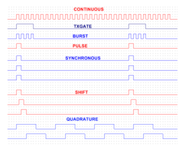
Figure 1 Excitation pulses for an ultrasonic system, a) continuous fix frequency, b) pulse gate, c) burst, d) single pulse, e) synchronous and simultaneous channels, f) shift pulses, g) quadrature pulses.
Figure 1 shows; a) an excitation signal with fixed frequency and continuous mode, b) gate pulse, c) an excitation signal in pulse burst mode in which the repetition frequency and the number of cycles may be programmable for systems in pulsed mode, d) single pulse, e) several channels with simultaneous excitation pulses for excitation of transducer arrays, f) multiple channels with shift pulse excitation for arrays with focusing applications, g) 2 channels with excitation in quadrature. In medical applications where bidirectional blood flow is detected, signals in quadrature are used for the demodulation of Doppler signals [2-3]. These pulses can be generated independently or in combinations, such as simultaneous pulses and shift or burst.
In applications where it is required to focus dynamically the ultrasonic beam, transducer arrays are used with multiple piezoelectric elements, such as that shown in Figure 2. For excitation of multiple elements pulse bursts are required which can be generated simultaneously or out of phase (with time delays between them) in order to generate dynamic wave fronts.
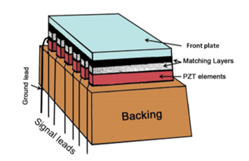
Figure 2. Linear transducer array
The focal depth is determined by the time delay between the electrical pulses. This can be changed electronically to focus pulses to give a good image detail at various depths within the body rather than just one depth with fixed focus transducer. One approach is to create an image by using a sequence of pulses, each one focused to a different depth or zone within the body. The acoustic parameters of the resulting beam, such as incidence angle, focal length and focal point size can be manipulated by the generated front waves in the array, controlling the excitation pulses via software [2].
A pulse generator to excite PZT and PVDF transducer arrays is presented. This pulse generator is based on a PSoC-5LP (Programmable System on Chip) programmable module, which is a USB port programmable development kit, from Cypress Semiconductor PSoC. [2-4]
The PSoC-5LP module has a microcontroller and a set of analog and digital programmable peripherals, all in one integrated circuit along with a 32-bit CPU (ARM Cortex family), The PSoC in the development kit belongs to the 5LP family; this family has an ARM Cortex M3 CPU with a clock rate that can reach up to 80 MHz [4].
The main difference between the PSoC microcontroller and conventional microcontrollers is that in the latter the set of peripherals are defined by the manufacturer, while the PSoC due to its programmable logic composed by Universal Digital Blocks (UDBs) and a set of analog and digital peripherals can be programmed (customize) in order to perform the required functions [5].
The implementation of the design of the programs for PSoC is made using its own IDE (Integrated Design Environment) PSoC Creator 3.2 Service Pack 2[6]. The programming process requires of a schematic diagram design, then an assignment (input/output port), and finally if required to write a C program, this process is integrated in programmable analog logic and digital functions.
2. Methodology
In this work, a programmable CY8CKIT-059, PSoC 5LP module was used.
The PZT transmitter transducer used is a 64 elements linear array (Krautkramer 116-001-264 model) [9], this PZT array has an operating frequency of 3.5 MHz (Figure 3a).
A PVDF Piezoelectric Transducer Sensor (SDT1-28K model) from Shielded Measurement Specialties [7-8] (Figure 3b) and an Ultrasonic Pulser Receiver, Olympus 5072PR (30 dBs amplifier) were used for the reception of the ultrasonic pulses
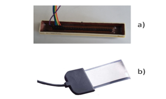
Figura 3: a) Top view of the PZT transmitter array; b) PVDF Piezo transducer Sensor, SDT1-28K model, (16 mm x 30 mm and thickness 75 µm).
To excite the PZT transducer array, it was required to generate 3.5 MHz pulse bursts corresponding to the operating frequency of the array, with a 10 kHz repeating frequency. These pulse bursts are shown in Figure 4.
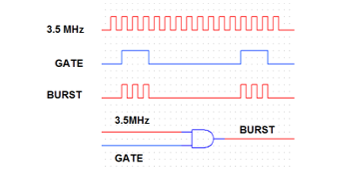
Figure 4. Time diagram of the excitation pulses of the PZT array.
In order to generate the operating frequency of the PZT transducer, the internal PSoC clock was programmed at 40 MHz. An UDB in PWM mode (PWM_35M) was also implemented to obtain a 3.5 MHz frequency, as illustrated in Figures 5 and 6.
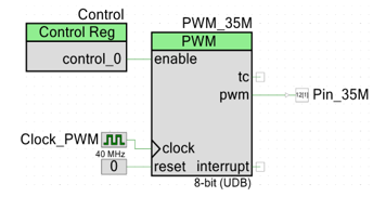
Figure 5: Implementation of the 3.5 MHz clock.
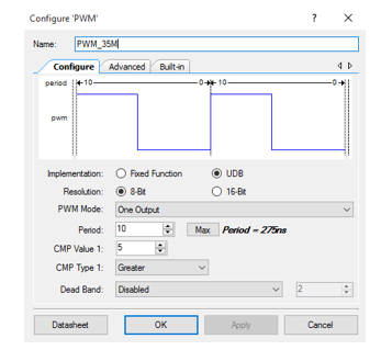
Figure 6. UDB PWM dialog window
In order to generate the 10 kHz repetition frequency a second UDB in PWM mode (PWM-Gate) was used in conjunction with an AND gate to generate the burst pulse, as shown in Figure 7.
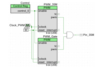
Figure 7 . Implementation of the excitation pulse bursts.
To test the excitation pulse generator, an experimental platform like the one shown in Figures 8 and 9 was implemented. A PSoC CY8CKIT-059-5LP module was used to generate the pulses and excite the PZT transducer elements. A PVDF transducer was used as a receiver, then the signal is amplified 30 dB and acquired with a digital oscilloscope, finally this signal was processed on a personal computer.
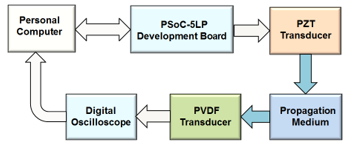
Figure 8: Block diagram of the experimental setup.
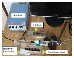
Figure 9: Experimental setup.
3. Results
To test the pulse generator, pulse bursts were programmed in four output ports, which can deliver pulse bursts simultaneously or out of phase as shown in Figures 10 and 11.
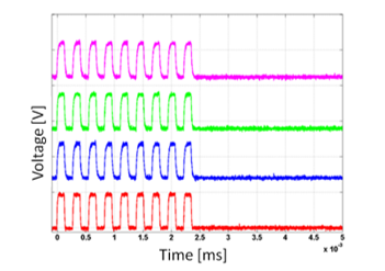
Figure 10. Simultaneous pulse bursts.
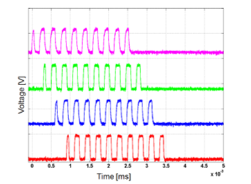
Figure 11. Out of phase pulse bursts.
Pulse generation of the four output ports was obtained by repeating the implementation shown in Figure 7 for simultaneous outputs and programming a 25 ns time delay between them for the out of phase outputs.
Using an experimental platform like the one shown in Figure 8, two experiments were conducted. The first experiment consisted in generating pulse bursts in four output ports to simultaneously excite four piezoelectric elements of the PZT 64 elements array (Figure 2), then more pulse bursts were generated in four ports to exciting the PZT array but this time with a 25 ns delay between each port. The results of this experiment are shown in Figure 12. Figure 12a shows the acquired signals with simultaneous excitation and Figure 12b shows the acquired signals with phase shifted excitation. The signals were acquired using a linear PVDF transducer array.
The second experiment was similar to the first one, the only difference consisted that in the acquisition of the signals, a single PVDF transducer was used. Figure 12a shows the acquired signals with simultaneous excitation and Figure 12b shows the acquired signals with phase shifted excitation.
The wave fronts generated by the four elements of the linear PZT array are shown in Figure 12, and correspond to a distance of 30 mm between the PZT and PVDF transducers. The signals have a 30 dB gain with a 500 ohms input impedance. 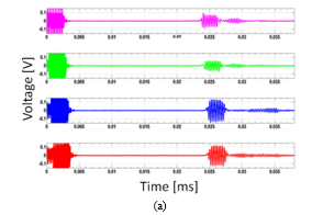
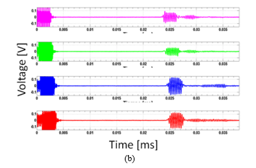
Figure 12. PVDF transducer response as a receiver, with one element at a time, with amplification of 30 dB (a) Simultaneous and (b) out of phase.
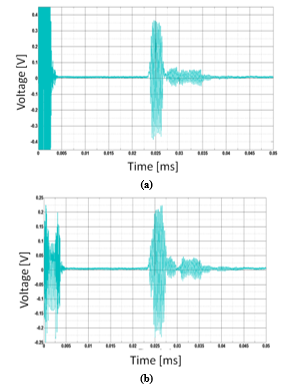
Figure 13. PVDF transducer response as a receiver, receiving the signal from four elements of the array at the same time, with amplification of 30 dB (a) Simultaneous and (b) out of phase.
4. Discussion
The precedent of this research work was the implementation of a pulse generator using the Arduino Mega platform [3], in this implementation it was not possible to obtain synchronous pulses in multiple output ports with frequencies above 120 kHz, since its programming does not allow it. Instead the PSoC modules have a programmable hardware that allows programming the operation clock signal and thus programming output ports with a wide frequency range. It is also possible to program simultaneous output ports and phase shifts between ports, since such delays between signals are implemented with a delay by software of one cycle of the master clock. There is also a previous article in which this subject is presented with less extension [10].
A pulse generator based on a PSoC-5LP to excite PZT and PVDF transducer arrays is presented, it is possible to excite PZT or PVDF elements with 5 volts of amplitude, for applications requiring more power additional voltage power supply and current drivers are required. Figure 14 shows two PZT driver circuits, a) single pulse and b) burst.
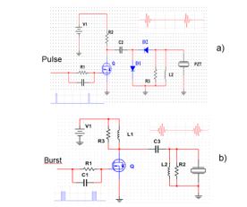
Figure 14. PZT driver circuit, a) driver circuit for single pulse, b) driver circuit for burst pulse.
5. Conclusions
The pulse generation with PSoC-5LP modules is a good alternative because as demonstrated in this work, it is possible to generate different pulses to excite transducers, either in one or multiple output ports, continuous or pulse burst, simultaneously or out of phase.
The advantage of the pulse generator implemented using the PSoC-5LP module with respect to commercial generators is its versatility. It can operate programmable frequencies from 3-74 MHz, which covers a wide range of ultrasonic applications
With the pulse generator implemented in the PSoC-5LP module, it is possible to excite PZT or PVDF elements with 5 volts of amplitude, resulting in an excellent alternative for low power ultrasound applications.
Conflict of Interest
The authors declare no conflict of interest.
Acknowledgment
Authors thank DGAPA for its support, projects PAPIIT IN106016 and PAPIIT IT101316.
- Antonio Arnaud Vives. Piezoelectric Transducers and Applications. Second Edition. Berlin Heidelberg, Springer, 2008.
- Pedro Acevedo, Mónica Vázquez, Joel Durán, Rodolfo Petrearce. “A pulse generator based on an Arduino Platform for ultrasonic applications,” 2015 International Congress on Ultrasonics, 2015 ICU Metz Physics Procedia 70, 1096-1099, Elsevier 2015
- Pedro Acevedo, Carlos Díaz, Mónica Vázquez, Joel Durán. Design of a Pulse Generator Based on a Programmable System-on-Chip (PSoC) for Ultrasonic Applications. International Journal of Mechanical, Aerospace, Industrial, Mechatronic and Manufacturing Engineering Vol:10, No:3, 453-456, 2016. World Academy of Science, Engineering and Technology. USA.
- PSoC 5LP. Architecture Technical Reference Manual. January 2016. Cypress Semiconductor Corporation. Web site: http://www.cypress.com/file/123561/download.
- PSoC 5LP Prototyping Kit Guide. January 2016. Cypress Semiconductor Corporation. Web site: http://www.cypress.com/file/157971/download
- PSoC Creator TM Release Notes. January 2016. Cypress Semiconductor Corporation. Web site: http://www.cypress.com/file/213966/download
- Piezo Film Sensors. Technical Manual. December 2015. Measurement Specialties. Web site: http://www.meas-spec.com/piezo-film-sensors.aspx.
- SDT Shielded Piezo Sensors. December 2015. Measurement Specialties. Web site: http://www.meas-spec.com/downloads/SDT_Series.pdf
- Krautkramer Transducer Certification. Model 116-001-264. Krautkramer Branson Inc. 1999.
- Carlos Díaz, Mónica Vázquez, Martin Fuentes, Joel Durán, Pedro Acevedo. “Pulse Generator for Ultrasonic PZT and PVDF Transducer Arrays Based on a Programmable System-on-Chip (PSoC)”, 2016 13th International Conference on Electrical Engineering, Computing Science and Automatic Control (CCE), Mexico, City. México. Septiembre 26-30, 2016. 978-1-5090-3511-3/16 ©2016 IEEE.