Kinect-Based Moving Human Tracking System with Obstacle Avoidance
Kinect-Based Moving Human Tracking System with Obstacle Avoidance
Volume 2, Issue 3, Page No 191-197, 2017
Author’s Name: Abdel Mehsen Ahmada), Zouhair Bazzal, Hiba Al Youssef
View Affiliations
Department of Computer and Communication Engineering, Lebanese International University, Lebanon
a)Author to whom correspondence should be addressed. E-mail: abdelmehsen.ahmad@liu.edu.lb
Adv. Sci. Technol. Eng. Syst. J. 2(3), 191-197 (2017); ![]() DOI: 10.25046/aj020325
DOI: 10.25046/aj020325
Keywords: Kinect, Arduino, Tracking, Depth Image, Processing

Export Citations
This paper is an extension of work originally presented and published in IEEE International Multidisciplinary Conference on Engineering Technology (IMCET). This work presents a design and implementation of a moving human tracking system with obstacle avoidance. The system scans the environment by using Kinect, a 3D sensor, and tracks the center of mass of a specific user by using Processing, an open source computer programming language. An Arduino microcontroller is used to drive motors enabling it to move towards the tracked user and avoid obstacles hampering the trajectory. The implemented system is tested under different lighting conditions and the performance is analyzed using several generated depth images.
Received: 04 March 2017, Accepted: 14 April 2017, Published Online: 24 April 2017
1. Introduction
For the past years, the development of robot technology has significantly increased due to industrial and military applications. Human tracking robot is one of the applications that could be implemented under robot technology.
Because of its human following capability, human tracking robot can work as solutions for many problems or as assistants for humans in various situations. One of them would be to fight wars in place of humans as tracking and following the enemy to unknown places in order to reduce human casualties. It can also be used to help people with physicals problems to carry their objects [1] , [2].
To achieve this, it is required to use a sensor that measures variables within an environment where these variables can be processed and analyzed to detect a person.
There are several ways to implement computer vision. The first one is to use the 2D scanning like RGB cameras or stereo cameras that have 2 lenses to simulate human binocular Vision [3].
The second way is the 3D scanning like the time of flight that uses both the distance and time to calculate the point in 3D and the structured light that uses a pattern of projected light to calculate the depth image [4].
For example J. Hoang and J. Zhou designed an algorithm based on a color light sensor to model a person after a color histogram for person segmentation [5].
Another example was when a group of researchers created a person following robot using a light sensor capable to detect a person based on the color within a certain region of their clothing [3].
Some researchers have utilized an omnidirectional camera in conjunction with a laser based distance sensor to track a person. Those sensors are capable to detect light outside the visible spectrum [6].
This paper has involved the integration of Kinect sensor that beats any other camera by its ability to capture a direct depth image with high accuracy rate. This small, portable device provided developers with the foundation needed to create and deploy interactive applications that respond to people’s natural movement, gestures and voice commands [7].
One of the most amazing capabilities of the Kinect used is the skeleton tracking. This concept is used in this paper to map depth image to make a robot able to track human movements [8].
Another important part of this paper is the obstacle avoidance. The robot may face obstacles while tracking human, these obstacles must be observed and detected by the Kinect so that it would be able to move to the right direction without collide with them.
Robots have proven to be more useful for a wide range of industrial and commercial applications, principally in indoor environments since the outdoor environment brings more challenges and complications. In an indoor environment, the small size of rooms restricts the visual perception where tables, chairs and even walls are encountered as occlusions but it still more beneficial and robustness compared to the outdoor environment where the occlusions there: plants, bushes, etc. are more shaped complexly. In addition, when operating in an outdoor environment, lighting intensity is more dynamic, reducing the robustness of visual perception. So the third part of the paper is to study the flexibility of the Kinect while operating under various lighting conditions [9].
This paper is an extension of work originally presented and published in IMCET conference [1]. In this extended work, we first present the proposed system design, and then we show the evaluation of the Kinect performance in different lighting conditions.
2. Proposed System
2.1. System Design
The project deals with making a robot that will move towards a specific user and avoid obstacles encountered in its path.
The proposed system as shown in Figure 1consists of three main parts: Kinect sensor, Arduino and Processing.
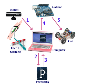
Figure 1: System Design
The Kinect is a motion sensing input device by Microsoft that consists of object detection, object tracking and reorganization. It enables users to control and interact with the applications using full skeleton tracking, gesture recognition and facial recognition and it can also be used to detect and distinguish between different kinds of objects. It has three eyes; 2 cameras and an infrared projector. The IR projector shines a grid of infrared dots and based on the triangulation between the observed and the reference patterns, the depth will be calculated [10].
Thus, the Kinect is used as an effective tool for discovering the surrounding area, calculating the depth image, detecting and tracking a specific human and locate their individual joints and body parts as illustrated in Figure 2.
The Arduino, which is an open source physical platform or microcontroller board, can take input from a variety of sensors and control a variety of motors, lights and others physical outputs [11]. In this project and in order to achieve the full control over the robot, the Arduino will be connected to the car motors.
The processing is an open source programming language used to access the depth data coming from the Kinect, analyze it and display it on the screen [8].
The robot was decided to be a car since it can serve part of the system’s demands in regards to the power, rotation and control. It consists of two motors; one is used for the motion and the other for controlling the motion direction of the car. Concerning the Kinect it is necessary to be located on the front of the car to avoid seeing the car parts as obstacle [1].
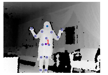
Figure 2: Skeleton Tracking
When turning the system on, the Kinect sensor, which is the main part in the system, starts capturing the depth image of the whole scene in front of it. The information captured by the Kinect must then be transferred to the computer where the processing is running. The processing will analyze the depth image and once it detects a user, it will determine his/ her center of mass which is the main point in tracking him/her and it has also to detect the obstacles between that user and the robot. Based on the analyzed data, the processing will send commands (like: left, right, forward, stop, etc…) to the Arduino serially via the computer, these commands will be already defined between processing and Arduino. Finally, the Arduino which will be connected to the car motors will receive the commands coming from computer, analyze them and order the robot to move in the right way.
Now, the robot can start tracking the user and avoid obstacles according to the information obtained from its “brain”, the Arduino, and build on scenes coming from its “eyes”, the Kinect [1].
2.2. Sequence Diagram
The sequence diagram in Figure 3shows the interactions between different parts of the system in sequential order.
- Start with the Kinect that captures depth image at 30 Hz [8].
- Pass by the processing that will analyze the depth image, detect the center of mass and send commands to the Arduino.
- Move to the Arduino, serially via the computer, which will receive the commands coming from processing, analyze them and order the Robot to move in the correct direction.
- End with a robot able to move towards a user and avoid obstacles detected in its path.
2.3. State Diagram
The robot will not move until a user is detected in front of the Kinect. Once this happens, the processing will track his/ her skeleton specifically according to his/her center of mass. If it failed to track the center of mass for a certain period of time, the processing will return back and wait for a new detection. Once the center of mass is determined, the robot should move towards the detected user and processing should maintain the distance between the robot and the user to check if any obstacle exists there. Now, the Robot should avoid obstacles detected and continue moving in the same way the user does. These steps are represented in the state diagram of Figure 4.
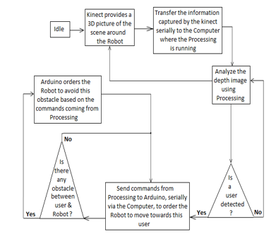
Figure 3: Sequence Diagram.
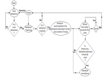
Figure 4: State Diagram.
3. Implementation
The project needs two kinds of software to be implemented, the first one which is the Processing is responsible for analyzing the surrounding information, detecting obstacles, recognizing the user and tracking him/her. The second software is the Arduino Software IDE which is responsible for controlling the robot movement based on commands coming from the Processing.
3.1. Processing
The processing code imports the necessary steps for performing user tracking and obstacle avoidance from the Simple Open NI library.
The first of these steps is to tell the Simple Open NI to turn on user tracking. That happens within the setup () by using enable User() function and to access depth data the enable Depth() function is used.
The Depth Map ()function is used to get the depth array and to save the coordinates of the closest value, each row in the depth image must be checked. In addition, each pixel the row must be observed and the corresponding value must then be pulled out from the depth array.
In skeletal tracking, the body parts of human such as head, neck, hands, legs, shoulders and arms are represented by a number of joints. Each joint is represented by its 3D coordinates [2]. Once a user has been detected and successfully calibrated, it uses the joint position data to have circles track the user’s joints where the main joint to track him/her is the center of mass (CoM). The real coordinates saved, shall be then translated into projective coordinates to match the 2 dimensional depth images.
As illustrated in Figure 5, the image is divided into three parts in width: left, middle and right where x is the width coordinate. If the closest value saved within 1 meter and the x value of the center of mass are in the same part of the image, then this closest value is an obstacle detected between the user and the robot [1].
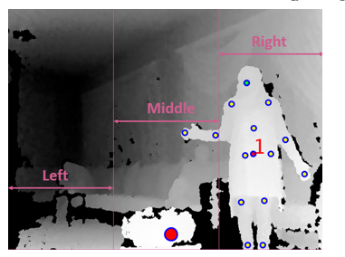
Figure 5: The three parts of the image
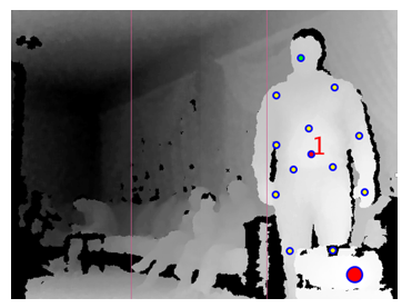
Figure 6: User and Obstacle in the same range (left side)
Depending on the Kinect data, there is an output send to the Arduino to be able to control the robot’s movements. For instance, to move: left, forward, right and stop.
The whole process begins when the user enters the view of the Kinect. At this point the Simple Open NI detects that the user is present and is a candidate for tracking within the On New User() function.
Now, in the case in which the user is located at a distance less than or equal to 1 meter the robot should stop immediately. Otherwise, it checks if the closest value and the center of mass of the user are in the same range; if so, then there is an obstacle that hampering the trajectory of the robot while tracking the user detected as represented in Figure 6. While if no obstacle is detected the robot will continue in its way toward the user as Figure 7 illustrates. This process ends when the user is no longer in the Kinect range by calling the On Lost User () function [8].
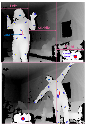
Figure 7: The user and the obstacle are in different range
The final task within processing was to send data from processing to Arduino serially via the computer, by importing the serial library, declaring a serial port and after matching the port on which the Arduino is connected a predefined value is sent on that port to enable the robot to move in the correct direction by using the write method. For example, in the case in which the user is in the left range and there is no obstacle in that range, the value ‘3’ is written on the port.
3.2. Arduino Software
The brain of the robot will be an Arduino microcontroller. So, the Arduino Mega 2560 board will be used for its large memory and available ports that make the installation more flexible [12].
To order the robot to move in the correct direction based on the data captured by the Kinect, the processing will communicate with the Arduino serially via the computer. Serial is a simple protocol that allows Processing to send information to the Arduino and vice versa [8].
The basic thing to do is to program the input and output ports, and give the order to apply a specific function at the output once a specific input is received on a specific input port [1].
The Arduino will establish a serial connection to the computer by using the serial.begin () function and then listen for data available on the serial port by using the serial.available () function. This function will return true if any data is available to read and false otherwise. To read the available data the serial.read () function is used [11].
If the received output from the processing is ‘3’, the Arduino should give its command to the system to move left, and thus digital Write function is used to set the pins to the required values.
All other directions are defined in the same; by setting the output pins as desired once receiving a specific input.
3.3. Lighting Conditions
The purpose of this part is to analyze the influence of different lighting conditions in the range of Kinect performance.
Six different scenarios, as shown in Table 1, were made under various light conditions producing a set of depth images from the Kinect. For example, scenario 3 is the case in which the Kinect was placed under sunlight while the user was under environmental light [13].
Table 1: Lighting Conditions Scenarios
4. Simulation Results
The first stage within the processing code was to detect a user, draw his/ her skeleton, detect his/ her center of mass and give him/her a specific ID. This stage was successfully done where the result in Figure 8 shows the skeleton of three different users with their specific IDs.
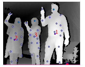
Figure 8: The skeletons of three different users
The next task was to keep track of the first user entering the Kinect range so that the output on the console indicates the movement and position of that user. Figure 9 and Figure 10illustrate the expected results.
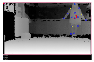
Figure 9: The output is “right”
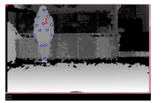
Figure 10: The output is “left”.
As displayed in Figure 11, Figure 12 and Figure 13the obstacle detection and avoidance stage was successfully done so that the output on the console indicates where the robot should move to avoid any detected obstacle.
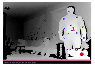
Figure 11: Incoming obstacle, go to the left.
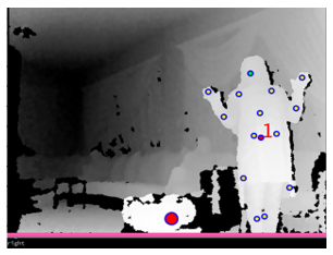
Figure 12: Go right towards the user.
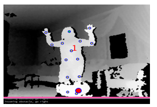
Figure 13: Incoming obstacle, go to the right.
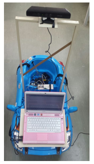
Figure 14: Final prototype of 3D sensor-based Moving Human Tracking Robot with Obstacle Avoidance.
The Arduino was connected to the laptop and the Processing code was run where it started to print the results: Forward, right, stop…etc., according to the state of the user and the allocated obstacles in front of it. The Arduino output is then measured using a multimeter where the measurement ensures the successive work in connecting the Arduino to the Kinect serially.
Finally, all parts were assembled together to get the final system illustrated in Figure 14.
Figure 15 presents the expected results such that tracking the human movement and avoiding the obstacles coming in its way became feasible.
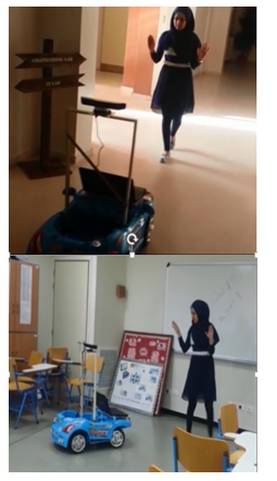
Figure 15: A User followed by the Robot.
5. Lighting Conditions Results
Concerning the lighting conditions, the results of the six scenarios studied, shown in Figure 16, were analyzed.
In scenario 1, in the presence of sunlight over both the Kinect and the user, and in scenario 2, where the Kinect was placed under environmental light and the user still under sunlight the Kinect was not able to obtain the depth information of the user.
Scenario 3 shows a higher intensity over the user with no skeleton joints detected since the Kinect was placed under the sunlight.
While in scenario 4, where only a part of the user was under sunlight, the Kinect was able to capture the depth information of the second part of the user.
For scenarios 5 and 6, where environmental and artificial lights were present, the Kinect performance is acceptable.
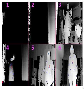
Figure 16: The depth images of the Kinect under various lighting conditions.
It was found that lighting conditions affect Kinect’s performance and that the sunlight is the main enemy for the Kinect. So try to avoid having sunlight on the user and don’t let the Kinect directly faced it.
6. Conclusion
The paper described the specifications of the Kinect sensor and how it can be integrated as the vision system of the robot. It also presented an experimental study of its performance under various light conditions.
The information of the Kinect were accurate enough to integrate a human tracking robot able to track a specific user in an indoor environment and avoid any obstacle detected in its path.
The project used the Kinect skeleton data to find the location of the user’s center of mass. This value is then sent to the Arduino so that it can match the movement of the user with the robot’s motor.
Our testing for this platform shows that the Kinect can be used as a powerful and useful device in many fields and that the combination between the Kinect and Arduino is as an advanced step in 3D Kinematics and interactive projects. Many system improvements will come in further works.
- Abdel Mehsen Ahmad, Hiba Al Youssef, “3D- Sensor based Moving Human Tracking Robot with Obstacle Avoidance,” in IEEE International Multidisciplinary Conference on Engineering Technology (IMCET), Lebanon, 2016.
- Satish Prabhu, Jaly Kumar, AmanKumar Dabhi, Pratik Shatty, “Real Time Skeleton Tracking Based Human Recognition System using Kinect and Arduino,” in National Conferene on Role of Engineers in Nation Building (NCRENB-15).
- T. Yoshimi, M. Nishiyama, T. Sonoura, H. Nakamoto, S. Tokoura, H. Sato, F. Ozaki, N. Matsuhira, and H. Mizoguchi, “Development of a person following robot with vision based detection,” in Proceedings of the IEEE/RSJ International Conference on Intelligent Robots and Systems, IEEE, Beijing, China, 2006.
- K. Jungling and M. Arens, “Feature based person detection beyond the visible spectrum,” in Proceedings of the IEEE International Computer Society Conference on Computer Vision and Pattern Recognition Workshop, IEEE, Miami, Florida, 2009.
- J. Zhou and J. Hoang, “Real time robust human detection and tracking system,” in Proceedings of the IEEE Computer Society Conference on Computer Vision and Pattern Recognition, IEEE, San Diego, California, 2005.
- M. Kobilarov, G. Sukhatme, J. Hyams , and P. Batavia, “People tracking and following with mobile robot using omnidirectional camera and a laser,” in Proceedings of the IEEE International Conference on Robotics and Automation, IEEE, Orlando, Florida, 2006.
- Jose Henrique, “Using Kinect fo Smart Costume Design,” August 2012. [Online]. Available: http://www.macs.hw.ac.uk/cs/msc_dissertations/2012/3.pdf.
- Borenstein, Greg, Making Things See, O’REILLY, Ed., 04 – 01 -2012.
- R. Seggers, “People Tracking in Outdoor Environments,” Amesterdam, 2015.
- Martin Kvalbein, “The use of a 3D sensor (Kinect™) for robot motion compensation.,” 12 May 2012. [Online]. Available: https://www.duo.uio.no/handle/10852/9069.
- “Arduino Official Website,” [Online]. Available: http://www.arduino.cc/en/Main/Software.
- “Arduino Board Mega,” [Online]. Available: http://www.arduino.cc/en/Main/arduinoBoardMega.
- J.R. Ruiz Sarmiento, C. Galindo and J.Gonzalez Jimenez, “Experimental Study of the Performance of the Kinect Range Camera for Mobile Robotics,” Universidad de Malaga, Andalucia Tech, Departamento de Ingeniera de Sistemas., Malaga, Espana.