A Cost Effective Security Technology Integrated with RFID Based Automated Toll Collection System
A Cost Effective Security Technology Integrated with RFID Based Automated Toll Collection System
Volume 2, Issue 3, Page No 1777-1783, 2017
Author’s Name: Rafiya Hossaina), Moonmoon Ahmed, Hasan Uz Zaman
View Affiliations
Department of Electrical and Computer Engineering, North South University, Dhaka, Bangladesh
a)Author to whom correspondence should be addressed. E-mail: rafiya_2012@yahoo.com
Adv. Sci. Technol. Eng. Syst. J. 2(3), 1777-1783 (2017); ![]() DOI: 10.25046/aj0203217
DOI: 10.25046/aj0203217
Keywords: RFID technology, Text message, Toll charge

Export Citations
Crime statistics and research on criminology show that under similar circumstances,crimes are more likely to occur in developing countries than in developed countries due to their lack ofsecurity measures. Transport crimes on highways and bridges are one of the most common crimes in the developing nations. Automation of various systems like the toll collection system is being introduced in the developing countries to avoid corruption in the collection of toll, decrease cost and increase operational efficiency. The goal of this research is to find an integrated solution that enhances security along with the advantage of automated toll collection. Inspired by the availability of many security systems, this research presents a system that can block a specific vehicle or a particular type of vehicles at the toll booths based on directives from the law enforcement agencies. The heart of the system is based on RFID (Radio Frequency Identification) technology. In this system, by sending a text message the law enforcement agency or the authority that controls the toll booths can prevent the barrier from being liftedeven after deduction of the toll charge if the passing vehicle has a security issue. The designed system should help the effort of reducing transport crimes on highways and bridges of developing countries.
Received: 31 May 2017, Accepted: 29 August 2017, Published Online: 23 September 2017
1. Introduction
Developing countries are still lagging behind in technological development compared to developed countries. Security systems and safety measures to stop crime in developing countries are still dependent on trivial manual systems rather than automated systems. A major portion of crime happens at the highways and bridges. Most of the hijackers, kidnappers, murderers, anddrug dealers usually try to change their location by travelling from one state to another. As most of the roads and bridges have toll booth in developing countries, they have to pass through those areas. But police sometimes fail to recognize the criminals and their transport vehicles. However, in our work we tried to develop a system at the toll booth area to mitigate this problem. For this, we have integrated an advanced security system along with automated toll collection system based on the RFID technology.This paper presents the completed work of a research whose initial results were published in a conference paper [1].
For implementing this system, we need RFID tag in every vehicle. Moreover, every vehicle owner’s basic information will be recorded in the database along with their prepaid based account number. So, it will be easier for the authority to find the vehicle owner’s details in a faster way in case of emergency. For instance, suppose a car has been stolen from a state. Usually stolen cars are removed secretly out of the state and for this it has to pass any of the bridge. However, the victim can write a General Diary (GD) at the police station and the police can inform the authority about the specified RFID number plate and thus the particular vehicle can be prevented from crossing the exit point at the toll bridge. Thus, the missing car can be found easily.
The overall system is a hassle free and user friendly secured system. The benefits of the system also include congestion reduction, time saving, operating cost saving, payment flexibility, and incident reduction.
2. Literature Review
A considerable research work has been going on regarding automation of toll collection system to replace manual toll collection system. Most of them are based on RFID technology as it is cost effective and also safer at the same time. Prepaid based account is needed for deducting the toll charge from the vehicle owner’s account. This system is much more convenient, safer and it also reduces traffic congestion at the highways and bridges.
In 2005, Jerry.L and Barbara.C proposed a technique which was based on smart card [2]. Later, in 2011 Hitachi.S had proposed a system using ARM-7 processor and that reduced the overall process time to a great extent [2]. The vital part of the system is the RFID. A study related to sustainability of passive RFID technology for fast moving vehicle identification was found in a research paper [3]. This paper talks about the ALOHA based anti-collision algorithms to identify moving vehicles. The simulation work was developed using C++ and three configurations which includes one, two and multi traffic lane [3].
However, some research is also going on in the area of intelligent safety and security of automobiles by implementing different types of sensor and wireless locking and unlocking systems to reduce road accidents [4][5]. Cyber security is another big concern nowadays. Research on data security is also going on in many ways [6].
We have analyzed some research on car parking systems and we found RFID based access control system that is used in some confidential areas. A tracker based automatic detection of suspicious behavior of pickpockets in a shopping mall related work is also been proposed in a research paper [7].
RFID identity card system is already available in hostels, universities, medical centers, and shopping malls to restrict the entry of unauthorized people [8]. Combining all the ideas, we have aimed at developing an advanced security system which will be integrated with the RFID based toll collection system and will provide higher security on highways or bridges.
3. Description of the Proposed System
The overall system model is designed based on our previous project ideas and some new concepts regarding RFID technology. For implementing this system in a country, all vehicles must hold RFID number plates or tags. After the vehicle enters the toll booth area, the RFID reader at the toll booth instantly reads the vehicle’s identification number and detects the vehicle type from memory. Then, according to the preset toll charge for each type of vehicle, it deducts toll charge from the vehicle owner’s prepaid based account.
In case of truck or other weight carrying vehicles, like-cargo, it uses a formula to calculate the toll charge amount as the weight varies. However, a confirmation text is sent immediately to the vehicle owner’s phone. So, to execute the system, the database has to record all the information including National ID card number, phone number, and account number etc. of the vehicle owner.
If any sort of crime occurs at the highways or bridges and the criminal wants to escape by moving into another state, he has to cross some toll booths. For example, if a murderer or a drug dealer is crossing a certain toll booth and the police somehow get informed about it, they can simply resist them. For this, they will only send the RFID tag code or number of the vehicle to the authority if they want to stop that vehicle. Then the system controller will send the code text to the system and block that vehicle even after paying the toll amount. In this way, if a security concern issue arises, the authority can also block all the vehicles from passing through that booth.
| Vehicle enters the toll booth area |
| Vehicle detection process through RFID card |
| Check truck or other vehicles? |
| Debit toll charge from prepaid account of the vehicle owner |
| After endorsement send confirmation text to the vehicle owner’s mobile |
| Check entry permission (black listed)? |
| Barrier will be uplifted and authentication text will be sent to the vehicle owner |
| Barrier will not be raised and vehicle will be restricted |
|
Calculate toll charge in database Total amount = Preset toll amount for truck + (additional weight)/2
|
| YES |
| NO |
| YES |
| NO |
| Check the toll charge according to vehicle type saved in the database |
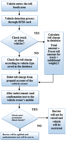 Figure 1: The Proposed System
4. Design Materials
The prototype of the system has been developed by using RFID system which includes the RFID Reader and RFID Tag, Microcontroller-Arduino Mega 2560, Force Sensitive Resistor (FSR), LCD Display, GSM Module and Servo Motor. The specifications of the components are briefly given below:
4.1 RFID Reader
A RFID reader is a network connected device (fixed or mobile) with an antenna that sends power as well as data and commands to the tags. RFID systems allow the unique identification of items [8] [9] or any other products which allows tracking of individual items throughout the supply chain. In our system, RFID reader is used to detect the RFID tag attached to the vehicle. The reader used in our prototype can read RFID tag within 3.5 cm. However, for the real time model we will use more powerful reader which can detect the RFID tag from a longer distance.
4.2 RFID Tag
Radio-Frequency Identification (RFID) is the use of radio waves to read and capture information stored on a tag attached to an object. In RFID system, every individual item is equipped with an inexpensive and small RFID tag. The tag contains a transponder with digital memory chip. An antenna packaged with a transceiver and decoder emits a signal activating the tag so that it can read and write data into it. When RFID tag passes through the reader zone, it detects the reader activation signal [8] [9]. For our prototype five different active RFID tags are used for identifying five types of vehicle
4.3 Arduino Mega
Arduino Mega is a microcontroller board based on the ATmega2560. It has 54 digital input/output pins (of which 14 can be used as PWM outputs), 16 analog inputs, 4 UARTs (hardware serial ports), a 16 MHz crystal oscillator, a USB connection, a power jack, an ICSP header, and a reset button [10]. In our prototype, two Arduino mega have been used.
4.4 Force Sensitive Resistor (FSR)
FSR is basically a resistor that changes its resistive value (in ohms Ω) based on the pressure it is given [11].In our system we have used a square shape FSR in place of weight sensor for the practical demonstration purpose.
4.5 LCD Display
A 16×2 LCD is used for displaying the deducted toll amount and vehicle types at the toll booth.
4.6 GSM Module
The technical design of the system includes a GSM module which will help to send a confirmation text to the vehicle owner about the toll deduction. It is also used to communicate with the security personnel hence control the access of vehicles.
4.7 Servo motor
Servo motor has been used in our prototype which rotates at 90 degree angle to control the barrier.
5. Hardware Design
The system contains two Arduino Mega 2560 as the microcontrollers. The first Arduino is connected with a Force Sensitive Resistor (FSR), GSM module and the RFID Reader. On the contrary, the other Arduino is connected with a GSM module, servo motor and a Liquid Crystal Display (LCD). Then, the Arduino-1 and Arduino-2 are connected through serial communication. However, we need to power up the two Arduino Mega 2560 with 9V~12V and 2A. To activate the GSM shield, we need to insert a SIM card with balance recharged and hold the button until the green light stop blinking and settle down. Finally, we need to pass the RFID tag or card in front of the RFID reader.
|
Arduino-2
|
|
Arduino-1
|
| GSM Module |
| LCD Display |
| RFID Card Reader |
| RFID Card |
| FSR |
| Servo motor |
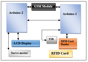 Figure 2: Hardware architecture
6. Software Design
The software design is constructed with two microcontrollers. The first processor is used to communicate with the RFID system, GSM module and FSR. However, the second processor combines the functionalities of GSM module, LCD display and servo motor. In the first processor, the system embarks by sending a tag request. If the vehicle carries a valid RFID tag, it sets or resets corresponding bits to the second processor [7]. After executing all these steps, it reveals the information in Liquid Crystal Display.
If valid tag is missing, then the former process backtracks again and thus the infinite loop continues. In the second processor, system activates by reading the analog voltage values A0, A1, A2 and then examines to determine the type of vehicle. For example, in case of truck it records the weight of the truck and the calculation is conducted by using the method below:
Total amount = Preset toll amount for truck + (additional weight)/2
For instance, if the vehicle is 50kg overweight, then the user has to pay half of the weight value along with the initial fixed amount.
After performing the calculation, it displays the corresponding data and sends confirmation text using AT Commands. Then, it sends command to rotate servo motor at 90 degree angle. After 30 sec of delay, it will rotate back into 0 degree angle again.
| YES |
| NO |
|
Start
|
| Checks if bit matches? |
| First processor receives RFID tag code through GSM module using AT commands |
| Second processor sends corresponding bits for the identified vehicles |
|
Stop commanding servo motor for rotating
|
| Servo motor rotates again (close) |
| Delay time (30 sec) |
|
Commands servo motor to rotate at 90 degree (open)
|
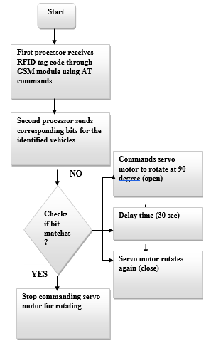 Figure 3: Steps for integrating between two processors
The security system starts when the first processor receives the RFID tag code by using GSM module. By using some AT commands, this process is done. After that, the second processor sends the currently available tag code. Then the tag code is matched with the currently available vehicle’s RFID tag code in the database. If it matches then the system stops commanding for the rotation of the servo motor. So, the barrier remains closed. However, if it doesn’t match, then the servo motor commands to rotate at 90 degree angle and eventually open the barrier. After 30 sec of delaying, the servo motor again rotates back at 90 degree angle to close the barrier.
To control the barrier for security purpose, we have used a code text message with the help of GSM module. The code text format for blocking the system is given below:
SMS Format: Block<space>Car/Bus/Truck/CNG/Bike
For example, to block a car the authority should write a text message to the system like Block Car and send it to the system.
| Security sends the vehicle’s RFID tag code to the system authority (Host) |
| Host sends code text message to the system |
| Vehicle is blocked by not lifting the barrier |
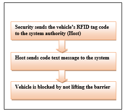 Figure 4: Blocking procedure
7. Results and Discussion
The designed prototype system has arranged a RFID booth over the road where the RFID reader was positioned for showing the demonstration. We had utilized a 16×2 Liquid Crystal Display for exhibiting purpose and also applied a 10k potentiometer to regulate the contrast of LCD display. We have used five different RFID tags or cards which represent five different types of vehicle, i.e., Bike, CNG, Car, Bus and Truck. A SIM card was inserted in the GSM module using which text messages were sent to the phone numbers that were already stored in the code for each RFID card.
The satisfactory level of our demonstration was adequate enough. The process started when a vehicle crossed RFID booth area, it was scanned instantaneously and informed by means of some LED’s in the circuit. At the beginning the LCD exhibited in the display ‘no vehicle……charge is 0’.In contrast, in case of vehicle without proper RFID tag, the LCD display showed ‘no tag present, use alternate path’. Rather than truck for the other four types of vehicle (Bike, CNG, Car, Bus), it showed in the LCD display the type of vehicle and the corresponding charge.
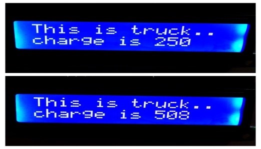 Figure 4: Toll charge for truck
We charged different amount of toll for the 5 types of vehicle. A confirmation text was received immediately in the phone number we had given in our system code. For truck the weight was calculated by varying the weight using FSR. For additional weight the extra toll amount that has to be paid was calculated using the following formula:
Previous Toll Charge for truck + (1/2) * weight = Total Toll charge for truck.
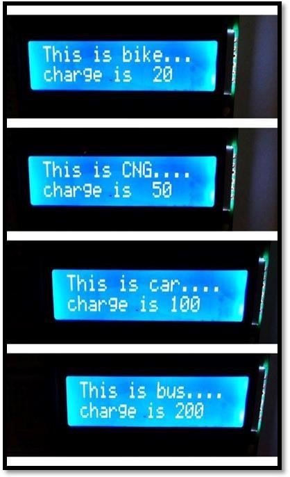 Figure 5: Toll charge based on different types of vehicle
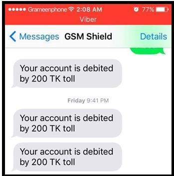 Figure 6: The example of authentication messages
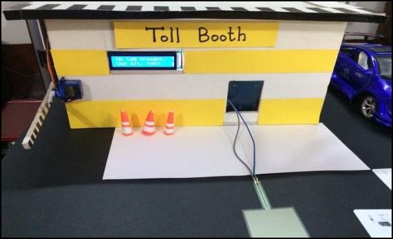 Figure 7:The prototype of proposed system
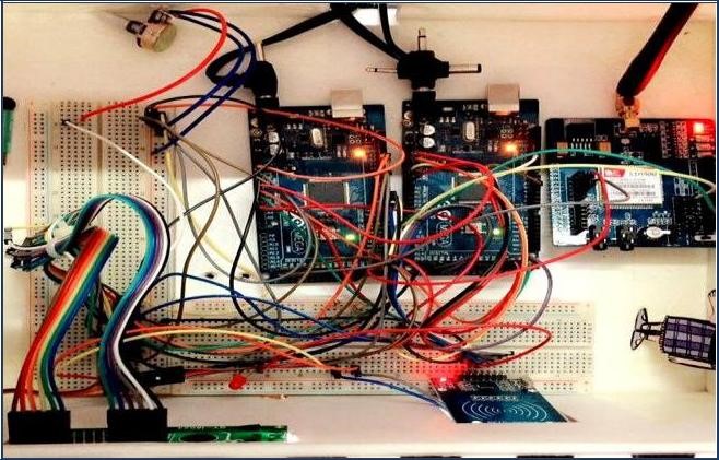 Figure 8: Internal circuit of the proposed system
7.1 The result of the security feature
In our demonstration, first of all we recorded five RFID cards in the database for five different types of vehicle. Now, we wanted to block the RFID card which was registered in our database system as ‘car’. For this, we sent a text message writing ‘Block Car’ to the system and then the LCD showed ‘Car Blocked’ and barrier was not lifted.
 Figure 9: The example of message format for blocking vehicle
 Figure 10: The example of screen for blocking vehicle
Then againwe wanted to block the whole system so that no vehicle can pass the toll booth area. For testing, we used the format of the SMS “All<space>Block” and sent a message to the system. After receiving the SMS, when we passed the RFID cards, the system blocked all the five types of vehicle and showed in the display “All Blocked”.
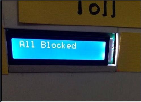 Figure 11: The example of screen for blocking all types of vehicle
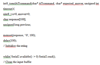 Figure 12: Part of coding used in the proposed prototype
The overall programming is done by using Arduino code. A part of our code is shown in Figure 12.
In order to determine the performance, the key matrices are the distance and the range of RFID reader and Card. Time is also the parameter depending on which the overall performance of the system was determined.
In our prototype, we have used an active RFID reader which can measure up to 3.5 cm distance. We did the distance vs efficiency calculation by checking how fast the RFID card is detected by the reader while passing the booth area and also kept the record when it was failed to do the detection process.
For the improvement of efficiency we need to use higher frequency ranged RFID reader. Taking some sample data we tried to generate the graph using MATLAB to see the performance approach over the distance.
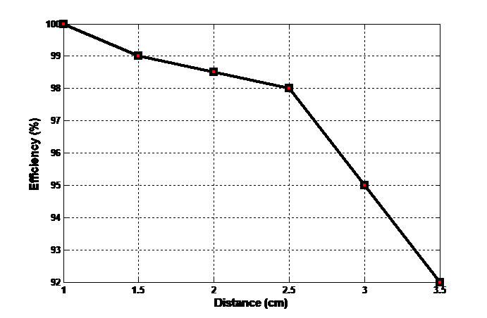 Figure 13: The comparison of efficiency and distance
From the graph, it is clearly visible that the efficiency of the system slowly decreases from 1cm to 2.5cm. After that the graph drastically decreases between 2.5 cm to 3.5 cm. Therefore, the finding is higher the distance lower the efficiency.
8. Cost Analysis based on the proposed prototype
One of the major steps for developing a compact system is taking into consideration about its building cost. As, our aim was to model the system for developing countries or underdeveloped countries, we tried to keep in mind about the cost issue. The system is very cost efficient and feasible for developing nations like Bangladesh, India, and Myanmar. Apart from that the components are easily available too. The whole circuit can be implemented on a PCB design board to have a compact design. The list and calculation of our total cost of the whole system are givenin Table 1.
9. Constraints
Junk messages are a problem which can hang the system. To erase the junk messages, the Reset button of the Arduino Mega 2560 is pressed. The latteris connected with the Liquid Crystal Display.
The implemented system has a short range for RFID tag detection, which are only a few centimeters at this time. This works fine in the small prototype system. Improvement of the system is possible by using more powerful RFID, which can be used for practical deployment with actual objects.
Table 1.Price of components and cost of the prototype system
| Components | Quality | Amount(BDT) |
| RFID Reader | 1 | 700 |
| RFID Card |
5
|
5×10=50 |
| Arduino Mega | 2 | (2×1200)=2400 |
| 16×2 LCD | 1 | 180 |
| GSM Shield | 1 | 3500 |
| Servo Motor | 1 | 320 |
| Potentiometer | 1 | 20 |
| Force Sensitive Resistor(FSR) | 1 | 912 |
| Breadboard | 2 | (2×120)=240 |
| Other materials | 678 |
Total 9000 BDT = 112.5 USD
10. Conclusion
The paper has presented the successful design of an embedded security system along with the automated toll collection system for reducing transport related crimes on highways and bridges. The overall system is based on RFID technology. Hence, there is no chance of using duplicate number plates as RFID tag is unique for each vehicle. The designed system should help the law enforcement agencies in many ways in reducing and preventing highway crimes. The system is cost effective and sustainable. It is expected that the system will sustain for a long time. It is also resistive to all external functions and parameters. For developing and underdeveloped countries, this automated security system along with automatic toll collection system should help greatly in reducing crime rates.
11. Future Work
A new feature can be added to the system which may include a database that stores vehicle data that includes vehicle owner’s photo, name, national identification number and residential address. After the vehicle with security problem is detected, the information in the database related to the owner will be immediately pulled and sent to the police close to the area via text messages.
Another feature can be added to the system in where CCTV can be placed at the toll booths. They will capture the image of the driver. The system will match the image with the images of known criminals with outstanding warrants. If there is a match, the toll boothwill block the passage of the vehicle and notify the law enforcement agency immediately.
Conflict of Interest
The authors declare no conflict of interest.
- R. Hossain, M. Ahmed, M. Alfasani, H. Zaman and R. Islam,”An Advanced Security System Integrated With RFID Based Automated Toll Collection System,” Proc. 3rd Asian Conference on Defence Technology(ACDT 2017), pp. 59-64, Phuket, Thailand, 18-20 January, 2017, DOI: 10.1109/ACDT.2017.7886158
- R. Kumar, A. Bennet, L.P and R.S, “Automatic Toll Gate System using Advanced RFID and GSM Technology”, Int. Journal of Recent Scientific Research,vol 7,issue 4, April, 2016.
- H.Khali, A. Araar and Z. Abdulla, “Sustainability PassiveRFID Technology for Fast Moving Vehicle Identification”, Journal of Imerging trends in Computing and Information Sciences, Vol 5, No. 1. Jan 2014.
- S. Nandhini and P. Kumar,” Automatic Toll Gate System Using, Advanced RFID and GSM Technology” International Journal Of Advanced Research in Electrical, Electronics and Instrumentation Engineering, Vol 3, 2014.
- T. Aphale, R. Chaudhari, and J.Bansod ,”Automated Toll Plaza Using RFID and GSM,” International Journal On Recent and Innovation Trends in Computing and Communication, Vol 2, No. 9.
- Y. Tseng and H.Pan ,” Data hiding in 2 color images”, “IEEE Transaction on Computers, Vol 51, Issue 7, Jul 2002
- H. Bauma, J. Bann, G. Burghouts and J. Rest,” Automatic detection of suspicious behavior of pickpockets with track-based features in a shopping mall”, Proc. SPIE, Amsterdam, September,2014,DOI:10.1117/12.2066851
- A.M.Win, C.M. New ,andK. Z.Latt ,”RFID Based Automated Toll Plaza System,” International Journal of Scientific and Research Publications, Vol 4, No. 6, June 2014.
- R. Hossain, M. Ahmed, M. Alfasani, H. Zaman and R. Islam,”Automated Toll Collection System,” Proc. 8th Intl. Conference on Electrical, Electronics and Civil Engineering (ICEECE’16), pp. 41-44, Dubai (UAE), Planetary Scientific ResearchCenter(PSRC)
- The Mega 2560 is a microcontroller board based on the ATmega2560. Retrieve from: http://www.arduino.cc/en/Main/ArduinoBoardMega2560
- FORCE-SENSITIVE RESISTOR (FSR). Retrieved from https://www.adafruit.com/products/166
- “Working Paper on future RFID Research Needs”, Cluster of European RFID Projects, September, 2007.
- P. Salunke, P. Malle, K. Datir and J. Dukale, “Automated Toll Collection System Using RFID”, IOSR J. of Comput. Eng., vol 9, issue 2, pp. 61-66 (January-February. 2013).