Control design for axial flux permanent magnet synchronous motor which operates above the nominal speed
Control design for axial flux permanent magnet synchronous motor which operates above the nominal speed
Volume 2, Issue 3, Page No 153-159, 2017
Author’s Name: Xuan Minh Trana), Nhu Hien Nguyen, Quoc Tuan Duong
View Affiliations
Thai Nguyen University of Technology, Vietnam
a)Author to whom correspondence should be addressed. E-mail: tranxuanminh@tnut.edu.vn
Adv. Sci. Technol. Eng. Syst. J. 2(3), 153-159 (2017); ![]() DOI: 10.25046/aj020320
DOI: 10.25046/aj020320
Keywords: AFPM motor, Optimal control above nominal speed

Export Citations
The axial flux permanent magnet synchronous motor (AFPM motor) using magnet bearings instead of ball-bearings at both two shaft ends could allow rotational speed of shaft much greater than nominal speed. One of the solutions to increase motor speed higher than its nameplate speed is reducing rotor’s pole magnetic flux of rotor (Yp). This paper proposes a method to boost the speed of AFPM motor above nominal speed by adding a reversed current isd of (Yp).
Received: 22 March 2017, Accepted: 07 April 2017, Published Online: 20 April 2017
1. AFPM Motor
1.1. Structure
In terms of structure, the AFPM motor has its own particular specialists, in details, the stator module may include several types: A single module has one winding set and a dual module has two sets of winding sharing a common core and back-to-back establishment. Similarly, a single rotor module includes only one permanent magnet on one side, and in dual module one, both sides have permanent magnets leaning against each other.
In this research, an object with two single module stator outside and one dual module rotor inside is designated as shown in Figure 1.
1.2. Principle of Operation
When a three-phase voltage is granted to stator coils, different currents are generated (including current iq) flowing inside, they will interact with the magnetics of rotor to generate torque (M) and the currents in phase windings (component id) of stator generate thrust and drag (F) based on the principle of the electromagnet. Thanks to special structure and above-mentioned operating principle, the rotor of the motor will not generate axial displacement although both ends of the shaft have magnetic bearings. It allows the absence of additional axial movement block of the rotor, therefore, the motor structure is being compact. Due to the way of winding roll, the rotational magnetic field generates torques M1 and M2 on the same direction on the rotor shaft and generates thrust-drag forces F1 and F2 between the rotor and the stator on opposite direction. The total torque (M=M1+M2) is the summation of the torques but the total force is the difference of the axial attractive forces (F=F1-F2).
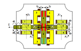
Figure 1: The AFPM motor section with magnetic bearing at both ends integrated (1: The shaft; 2, 3: the stator and the winding of left side and right side of motor; 4: the permanent magnetic rotor of motor; 5, 6: the magnetic bearing rotors on left and right sides; 7, 8: the stator and the winding of magnetic bearing on left and right sides; z0, g0: the nominal gaps between the rotor and stator of motor with magnetic bearings)
From the structure and the principle of operation mentioned above, AFPM motor can be considered as two motors that have a common rotor or share a common sharp.
2. Mathematical Model of the AFPM Motor
According to [1, 2, 3], the mathematical model of AFPM motor was developed in dq coordinate system, as presented on (1). The indicator 1 and 2 are present for the left side motor and right side motor, respectively.
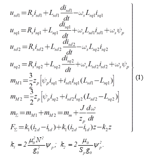
The stucture of AFPM motor as methematical model (1) is presented in Figure 2.
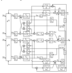
Figure 2: Structure diagram of AFPM motor
3. The voltage, current and magnetic space vectors of APFM motor in two working areas.
The voltage, current, and magnetic space vector of AFPM motor in two working areas are presented in Figure 3 [1, 5, 7]. From (1), it is clearly seen that the torque of AFPM motor includes two parts: the major part with multiplication ypisq and the reactive part due to the difference of stator inductance (Lsd-Lsq)≠0). In all operating condition, the AFPM motor must produce a sub-torque to compensate the reactive part. The clear existence of the reactive part normally neglected in classical control solutions. Ignoring that component helps to simplify control system and can be accepted in reality within nominal rotational speed, because in that range isd=0 (Figure 3a). On the contrary, in the speed range above the base speed, in order to speed up, the flux must be reduced by applying a negative current isd. The motor is now in flux weakening mode, the current is proportional to the rotor’s speed (Figure 3b). This leads to the reactive component of the torque is significant and it can’t be ignored.
When the motor’s speed is adjusted to above base speed, frequency is greater than the nominal frequency f1đm but its voltage cannot exceed the nominal voltage Uđm. The maximum value of voltage is U1 = Uđm. The motor’s electromotive force expression shows that the flux is inversely proportional to frequency, this is equivalent with the case that the flux of a DC motor is reduced to speed up.
Unlike the synchronous motor with the permanent magnet attached inside the rotor and reluctance synchronous motor, the AFPM motor operating in nominal speed range maintains the current isd=0. Therefore, we only consider the range of above nominal speed.
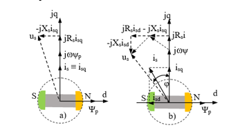
Figure 3: State vector of voltage, current and the magnetic flux of AFPM motor in two working areas: a) Under nominal speed; b) Above nominal speed.
4. Calculating the critical values of voltage and current:
Before introducing a variety of control strategies, we need to consider the limitation of current and voltage [4, 5]. The limitation of current vector:![]()
The current limit of (2) is a circular with radius ism in plane of (isd, isq)
The voltage limit vector: From the formula of the voltage at steady state neglecting the resistance of stator: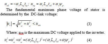
![]()
From (3) and (4), ignoring the stator resistances in the steady state, the currents isd, isq are defined. Substitute them into (1), the motor torque is obtained: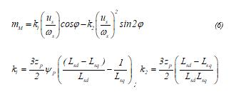
where: j is angle between stator voltage vector us and the q axis.
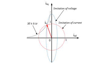
Figure 4: The limits and the optimal point of torque of the AFPM motor above nominal speed
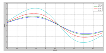
Figure 5: Simulation result of the motor torque with DC voltage U=400 V;
Figure 5 shows that if frequency is increased to speed up the motor to above base speed, the flux along with d axis will be decreased. However, if j is maintained at 60o then the motoring torque will be maximum.
5. Control design for AFPM motor
5.1. General control scheme
In term of structure, AFPM motor is completely different from conventional motors; its control scheme includes two different control loops: rotor displacement control loop (attractive force control) and speed control loop (motoring torque control). The general control scheme of AFPM motor is shown in Figure 6 [1, 3].
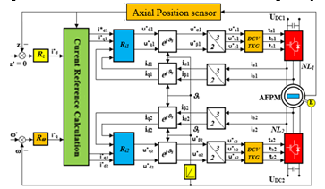
Figure 6: Vector control structure of AFPM motor
Vector control of AFPM motor is based on the analysis of the motor’s instantaneous currents into two components: the direct component id and the quadrature component iq. The direct component generates the attractive forces and the quadrature component generates the motoring torques. By this way, the control scheme of AFPM motor becomes similar to that of a DC motor.
The rotor displacement along z axis from its equilibrium point can be detected by displacement sensor. The detected value is compared to the reference value z* and the difference is inputted to the Rz controller. The reference z* is always set to make the rotor in-between the two stators at the equilibrium point. The output of Rz is used to compute the current reference . The reference and of the two stator windings can be calculated by using the compensating current id0: = + ; = – ; id0 can be zero or a small value around zero.
The rotor speed detected by the encoder is compared with the speed reference, the difference is fed to the speed controller Rw. The output of Rw is used to determine the q-axis reference current . The q-axis reference current of the two stator windings and is then calculated similar to id.
Control design implemented for AFPM motor includes following loops:
5.2. Current control
Most of the modern AC motor drives have a control structure comprising an internal current control loop. Therefore, the drive system characteristic depends on the quality of applied current control strategy [1, 3, 4, 5]
The main task of the current control loop is to make the motor’s currents follow the reference signals. By comparing the measured currents with the reference currents, the current control loop generates switching states for the inverter in order to decrease the current errors. In general, the current control loop performs two tasks: error compensation (reduce current error) and modulation (determine switching states).
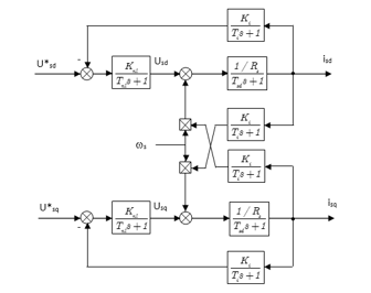
Figure 7: The current control loop of AFPM motor
The current control loop of AFPM motor as mentioned in Figure 7 is extracted from Figure 2 and following formulas: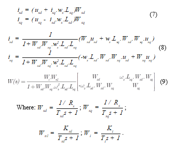
The formulas (7), (8), (9) show that interactive actions exist in current control loop. To obtain desire quality of the closed system, the modulus optimum criterion is applied: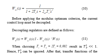
decoupling regulators for the current control loop can be determined.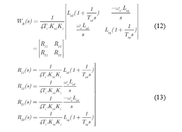
Insert the decoupling regulators into the current loop diagram in Figure 7 we have the decoupled diagram as shown in Figure 8.
5.3 Axial displacement control
For simplicity, assume that the radial movement of the rotor is supported by two ideal radial magnetic bearings. Thus, the axial displacement and the radial displacement are independent, and can be expressed as follows [1, 2, 3, 4]:![]()
where m is the weight of the motion part and F is the axial force.
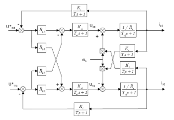
Figure 8: Decoupled current control loop
The equation (15) is obtained by substituting (1) into (14):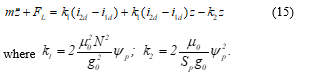
It is easy to see that this system is unstable. To make the system stable, a controller with derivative component is used. The axial displacement control loop is shown in Figure 9.
The axial displacement control loop contains the transfer function of the current control loop. Since the torque load is usually undefined, so it is regarded as an external interference.
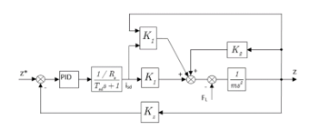
Figure 9: Axial displacement control loop
To eliminate the steady state error, a PID controller is used.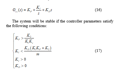
6. Quality evaluation by numerical simulation
6.1 Specifications of the motor and simulation parameters
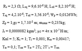
6.2 The simulation diagram of AFPM motor
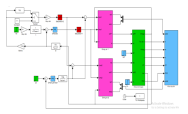
Figure 11: Simulink model of AFPM motor
6.3 Simulation results
When the motor operates at the nominal speed: n = 3000 rpm; m = 0,08 Nm; displacement z = 0
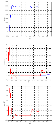
Figure 12: Characteristics of AFPM motor when it operates at the nominal speed and no axial force: n = 3200 rpm, displacement z = 0; the torque m (has the same shape as the current isq); isd = 0
When the motor operates above the nominal speed: n = 4000rpm; m = 0,08Nm; z ≠ 0
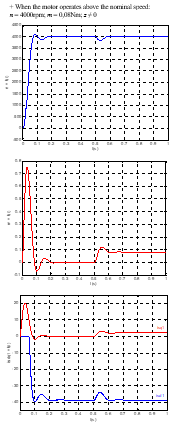
Figure 13: Characteristics of AFPM motor when it operates above the nominal speed: n = 4000 rpm, z ≠ 0; the torque m (has the same shape as the current isq); isd has large negative value.
7. Conclusions
The AFPM motor with special structure is used in combination with magnetic bearings to form a system which includes two control loops: the speed control loop and the rotor displacement control loop (with assumtion that the magnetic bearings fullfil their nominal functions). By using rotor flux oriented control method, some results are firstly achieved:
– Speed control above the nominal speed is attained by flux weakening thank to apply a current isd opposite in direction with the flux ψp while sustaining the torque.
– The rotor is always kept at the center of the motor by the rotor axial displacement control loop.
– Further research need to be implemented in order to improve the control quality and sustain the optimal torque when the flux is weakened.
– Experimental study on the AFPM motor.
- Nguyen Phung Quang and Jörg-Andreas Dittrich, “Vector Control of Three-Phase AC Machines”, springer
- Akira Chiba, adashi Fukao, Osamu Ichikawa, Masahide Oshima, asatsugu Takemoto and David G. Dorrell, “Magnetic Bearings and Bearingless Drives”, Newnes, 2005.
- Quang Dich Nguyen and Satoshi Ueno, “Analysis and Control of Non-Salient Permanent Magnet Axial-Gap Self-Bearing Motor”, IEEE Transactions on Industrial Electronics, Vol. PP, No. 99, pp. 1-8, 2010 (early access).
- Nguyen Van Lien, Nguyen Manh Tien, Doan Quang Vinh, “Control of AC motor with magnetic from semiconductor inverter“ NXB KHKT, 2005.
- Nguyen Duc Quan,“Modeling, simulation, and control reluctance high speed motor, Journal of Science and Technology – Da Nang University – No 11(96).2015 Book 2.
- Nguyen Doan Phuoc: “Nonlinear control theory”. NXB KH&KT, 2007.
- Trong Duy Nguyen, Gilbert Foo Hock Beng, King-Jet Tseng, Don Mahinda Vilathgamuwa, and Xinan Zhang: “Modeling and Position-Sensorless Control of a Dual-Airgap Axial Flux Permanent Magnet Machine for Flywheel Energy Storage Systems“, Journal of Power Electronics, Vol. 12, No. 5, September 2012.