A Secure Automated Elevator Management System and Pressure Sensor based Floor Estimation for Indoor Mobile Robot Transportation
A Secure Automated Elevator Management System and Pressure Sensor based Floor Estimation for Indoor Mobile Robot Transportation
Volume 2, Issue 3, Page No 1599-1608, 2017
Author’s Name: Ali Abduljalil Abdulla1, a), Hui Liu1, Norbert Stoll2, Kerstin Thurow1
View Affiliations
1Center for Life Science Automation (celisca), University of Rostock, Rostock 18119, Germany
2Institute of Automation, University of Rostock, Rostock 18119, Germany
a)Author to whom correspondence should be addressed. E-mail: Ali.abdulla@celisca.de
Adv. Sci. Technol. Eng. Syst. J. 2(3), 1599-1608 (2017); ![]() DOI: 10.25046/aj0203199
DOI: 10.25046/aj0203199
Keywords: Mobile robot, Multi-floor, Automated Elevator, Floor Estimation, Pressure Sensor

Export Citations
In this paper, a secure elevator handling system is presented to enable a flexible movement of wheeled mobile robots among laboratories distributed in different floors. The automated handling system consists mainly of an ADAM module which has the ability to call the elevator to the robot’s current floor and to request the destination floor. The LPS25HP pressure sensor attached to an STM32F411 microcontroller is utilized as a height measurement system to estimate the robot’s current floor inside the elevator. The ultrasonic sensor is used to recognize the elevator’s door status. Many challenges have to be solved to realize a stable height measurement system based on pressure sensor readings. The difference of the pressure sensor readings before and after soldering is realized by comparing the reading after soldering with an accurate barometric reading. In addition, the sensor output signal shows oscillation and wide variation of the same floor pressure sensor readings at different times. The oscillation in the output signal has been handled using a first order FIR smoothing filter. The first order filter was selected to balance between the stability and the elapsed time to receive the updated values. An auto-calibration stage is established to maintain the wide variation in the atmospheric pressure readings by calibrating the sensor readings with the robot’s current floor before entering the elevator. An error handling management system is utilized to guarantee a stable automated elevator management system performance. Many experiments to assess and verify the performance of the automated elevator management system and robot’s current floor estimation are reported. The experimental results show that the proposed methods and sub-systems developed for the mobile robot are effective and efficient in providing a transportation service in multiple-floor life sciences laboratories.
Received: 16 June 2017, Accepted: 29 July 2017, Published Online: 24 August 2017
1. Introduction
This paper is an extension of work originally presented at the International Conference on Mechatronics – Mechatronika (ME 2016) [1].
In this paper, a new method is presented to provide a transportation mobile robot with a secured elevator facility to move in a multi-floor building environment. The automated elevator with its management system uses a Wi-Fi signal for data transmission (order/status exchange). The automated elevator management system translates the number of the called floor into a specific pin and port. Then the pin and port number with the “on” order are sent to the ADAM module. After 100ms, an “off” order is sent. The selected ADAM module has four digital inputs and four relay outputs. The module is connected to the elevator entry button of four floors in a laboratory building. The main limitation of the automated elevator is that it does not provide any feedback about the elevator’s current floor or its door status, and thus pressure sensor based current floor estimation and an ultrasonic sensor based elevator door status reader are used. To utilize pressure as a current floor reader, many challenges must be considered. Firstly, differences in pressure sensor readings may occur before and after soldering. This problem is solved by applying a one-point calibration technique. Secondly, readings of the same floor pressure sensor vary at different times. A smoothing filter with an FIR structure is utilized to overcome small variations in sensor readings, while an adaptive calibration method handles wide variations during the week. Finally, the integration of the proposed elevator operation handling system in a real mobile robot transportation system in life sciences laboratories is initialized. Figure 1 shows the installed pressure sensor with its microcontroller board on the H20 Mobile robot. Over the last years, mobile service robots have played critical roles in many applications, including (but not limited to) medical [2, 3] and cleaning services [4, 5], agriculture [6, 7], operations in hazardous environments [8, 9], construction and demolition [10], space [11] and military applications [12], materials transportation [13], support services for the elderly and handicapped [14], and entertainment [15]. In contrast to certain service mobile robots used for surveillance and cleaning services, which can utilize random movement in performing their tasks, the majority of mobile robot applications requires a sophisticated navigation ability in order to move in the desired manner. Thus, an autonomous navigation system is a fundamental functional requirement. Mobile robots in automated laboratories are usually used for the transportation of samples and other material between sub-systems located in different places. The mobile robot has to solve four basic problems in order to achieve highly effective autonomous navigation, which are mapping, localization, path planning, and action. The mobile robot must either climb stairs or use an elevator to deal with complex building structures with multiple floor working environments. Legged robots and special designs of wheeled mobile robots [16] can climb stairs. However, climbing stairs during transportation tasks adds further challenges to the robot movement related to load capacity and balance preservation. Thus the elevator offers a suitable solution to this problem. An elevator handling system (EHS) includes many operations which must be accomplished in order to travel successfully on an elevator. The elevator entrance door and its status (open or closed) need to be recognized, the entry button must be detected, the destination floor button distinguished, and the current floor identified. Chen et al. presented a mobile service robot which has the abilities to both plan its own path as well as to call the elevator at each floor[17]. For the elevator calling operation, wireless control was designed. An Xbee module is employed to control the servo motor to push the elevator entry button. An RFID is utilized to approximate the current floor when the robot is inside the elevator. Experimental results demonstrated that the proposed mobile robot can ride the elevator and complete delivery tasks. This technique has many constraints, which would prevent its employment in life sciences laboratories. Firstly, each floor requires an electronic circuit consisting of an Xbee module, servomotors, microcontroller and power supply positioned beside the elevator for the call button pressing operation. Also, an RFID antenna would be required on each floor for current floor estimation, and finally this technique does not handle destination floor calling. Maneerat et al. presented a simple method for current floor estimation [18]. It is based on received signal strength (RSS) which is acquired from the number of wireless network sources installed on every floor. The main limitation of this method is the costs since it requires at least four wireless network sources on each floor to realize an acceptable success rate. Chen et al. presented a height measurement system using the MS5534B pressure sensor [19]. This sensor was attached to an LPC1114 microcontroller with the necessary peripherals attached to build the hardware platform. An experiment was conducted in a hotel covering 37 floors to examine the stability of the proposed system. However, this system does not take into consideration the wide variation in pressure sensor readings for one location at different times. Xia et al. presented a pedestrian floor estimation for smartphones [20]. A multi-reference barometer floor positioning method used multiple barometer sensors in each floor to determine a floor reference, and then the smartphone reading was compared with the floor reference to identify the current floor accurately. The method can overcome the problem of daily changes in pressure but the system will be expensive since it needs extra sensors for each floor, especially when applied with the highest number of floors and Floor-positioning servers. Frank et al. developed a motion estimation system to identify motion types, including walking, elevator, escalator, and stairs [21]. They use a Bayesian network to classify motion based on IMU and pressure sensors. The system estimates the kind of movement with value from 73.8 for falling detection to 95.5 for jumping. At CELISCA, researchers are working to develop the automated life science laboratory of the future. For a facility such as a laboratory, a system consisting of several H20 mobile robots has been established which allows samples, labwares and materials to be transported between individual automated sub-systems as support for laboratory staff or to replace them outside of working hours. In multi-floor transportation systems for mobile robots, the elevator aspect is a major topic to be handled. Two different working strategies are developed to guarantee secure glass elevator handling using automated and vision detection algorithms. Orders are sent to the elevator over Wi-Fi signals using the former, while the latter deals with the detection of entry and internal buttons and elevator door status, and controls the kinematic arm for the button-pressing operation. A pressure sensor is utilized as a stable floor estimation approach for both the automated and vision-based elevator handling.
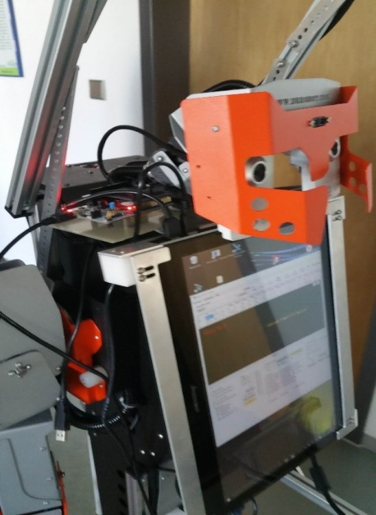 Figure 1 Installed Pressure Sensor with its Microcontroller board
This paper is organized as follows: the system structure is described in section 2, while section 3 explains the automated elevator management system, floor estimation based on the pressure sensor and the related smoothing filter, calibration stages, and integration into a real transportation system. The hybrid method to select a suitable elevator handling method is detailed in section 4. Section 5 describes four experiments conducted for system validation. The final section summarizes the results.
2. System Structure
At celisca, Rostock, Germany researchers have been developed a hierarchal management system to handle the processes of establishing a fully automated life science laboratories. This system has four control layers. The first layer has been divided into the Transportation and Assistance Control System (TACS), and Process Control Adapter System (PCAS). The TACS has a middle control layer which is the Robot Remote Center (RRC). This layer was established to manage the transportation tasks of mobile robots. It manages the robot by receiving a transportation order from the TACS then forwarding it to the Robot Board Computer (RBC) of an available robot which has the highest battery voltage. The Multi-Floor System (MFS) is the core component of the RBC level, and was developed to perform transportation tasks in multiple floor environments. As shown in Figure 2 the MFS is established to realize the functions of a multiple floor navigation system with a Robot Arm Kinematic Module (RAKM), Elevator Handling System (EHS), and Collision Avoidance System (CAS).
A multiple floor navigation system including mapping, indoor localization, path planning, an Internal Management Automated Door Controlling System, as well as the communication system, and Internal Battery Charging Management System has been reported earlier [22]. The MFS is integrated with the Elevator Handling System (EHS) to control elevator operation. The EHS consists of two sub-systems to handle the elevator operation as follows: elevator handling based computer vision [23] with kinematic arm solution for pressing operation [24]; and an automated elevator management system (AEMS). The Automated Elevator (AE) utilizes a WISE 4060 ADAM socket to call the elevator. An LPS25HB pressure sensor and STM32F411 microcontroller are used in the current floor estimation system hardware platform and are configured and programmed to overcome the inability of the AE to give any feedback about elevator’s current floor. The LPS25HB sensor is employed to measure the atmospheric pressure and the STM32F411 microcontroller to receive the raw data from the pressure sensor board, to filter them, and to send them to the MFS over USB cable.
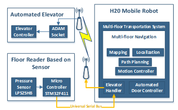 Figure 2 System Structure
3. Method Description
3.1. Automated Elevator Management System
The elevator is the key for the wheeled mobile robot to move among laboratories distributed on different floors in a complex building structure. Thus, it is necessary to establish a secure system to deal with the elevator. The system developed earlier was based on computer vision to deal with elevator operations (entry button detection, internal buttons recognition, and current floor estimation) [22], and the H20 arm solution [24] was developed for the button pressing operation. The weakness of the H20 arm joints can decrease the usability of this system. Thus, the AEMS is developed as a secure solution. This system controls the AE over Wi-Fi socket. The AE consists mainly of an ADAM module for calling the elevator and requesting the destination floor. WISE 4060 ADAM socket is a digital acquisition and control system over a computer network. It has the ability to collect data, and to remotely control the devices required to accomplishing integration between automated and enterprise systems through network technology. The ADAM mmodule consists mainly of a microcontroller, power circuit, Wi-Fi adaptor, four insulated digital inputs and four insulated high-speed relay outputs, and two watchdog timers (one for communication and the other for the system). It can be accessed using the IEEE 802.11b/g/n WLAN network either directly to the device (outdoor coverage area: 110m) or through a router/repeater to extend the coverage area. This module is embedded inside the elevator cabin and is connected directly to the elevator controller of the required floors to establish the AE as demonstrated in Figure 3. The AEMS is developed to connect the MFS with the AE. It translates the required elevator destination floor into a specific hardware port and pin numbers.
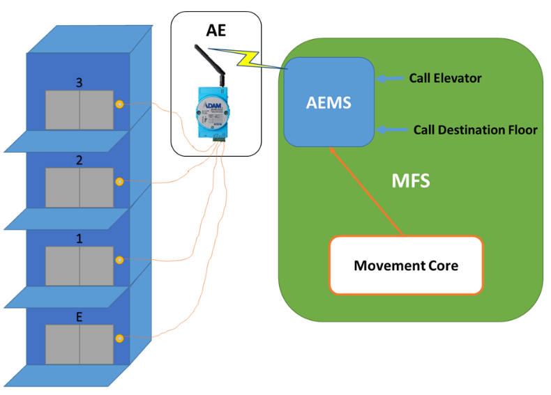 Figure 3 Automated Elevator with Adam Socket and Automated Elevator Management System
The AEMS calls the elevator to the robot’s current floor when the mobile robot needs the elevator to move to another floor during a transportation task. To identify the robot’s current floor outside the elevator, the indoor localization system developed earlier is utilized [22]. Inside the elevator, the MFS needs a logical solution to specify the destination floor. At this level, the movement core depends on the transportation task status (Grasp Position Done, Place Position Done, and Charge Position Done) to determine the current destination. When the robot enters the elevator, the movement core checks the current destination floor based on the current intermediate goal, as clarified in Table 1. For example, if the grasping operation has been completed, the placing operation floor has to be requested. Then the elevator is directed to go to the required destination.
Table 1 Destination Floor Selection Strategy.
| Grasp Position Done | Place Position Done | Charge Position Done |
Entry Button |
Internal Button |
| Not yet | Not yet | Not yet | Current Floor | Grasp Floor |
| Done | Not yet | Not yet | Current Floor | Place Floor |
| Done | Done | Not yet | Current Floor | Charge Floor |
The reconnection function is developed to handle the weakness of the Wi-Fi signal which connects the AEMS with the AE. As mentioned above, the AE is embedded in the elevator passengers cabin while the AEMS is a part of MFS which is the core of the RBC. Thus, the weakness in the Wi-Fi signal is related to the mobile robot’s large navigation area. This function starts to receive the updated elevator status. In case of missing data, the function closes the socket to AE and then initializes the connection again till a stable connection is realized.
3.2. Current Floor Estimation
The elevator is shared with human users in the building. Many people can use it simultaneously, and the elevator controller will respond to all requests based on the priority for moving direction (up/down).
For mobile robots, the current floor estimation technique is a topic aspect to consider. This technique is employed to inform the robot about its current floor inside the elevator. Earlier a vision system is utilized to recognize the current floor number. This was installed in the glassy elevator shaft for each floor to estimate the current floor [23]. This method has a high success rate in recognizing the correct floor in cloudy weather conditions. However, in some situations (such as a human forming an obstacle between the robot and the floor number indicator, or the disability of the vision sensor to recognize the floor number indicator at some times of the sunny day because of sunlight reflecting over the number mark) the robot completely fails to estimate its current floor. These limitations make this method an inappropriate solution for multiple floor transportation task since incorrect current floor estimation can make the robot lose its way to the destination. Thus, a new innovative method based on a height measurement system is developed to estimate the elevator current floor for mobile robot applications to enable a secure navigation system.
As a hardware platform for the height measurement system, the LPS25HB pressure sensor and STM32F411 microcontroller were configured and programmed to sense the environment and detect the current floor position. Many challenges have to be solved to use the pressure sensor as a floor estimation system. A soldering drift, which is defined as the difference between the accuracy of the sensor before and after soldering, appeared when the pressure sensor was attached to the STM32F411 microcontroller. A one-point calibration technique was used to solve the soldering drift problem by comparing the pressure sensor readings after attachment with a precision barometer. The difference was calculated and added as an offset to each pressure sensor reading. In addition, absolute digital barometer (pressure sensor) readings at the same floor of the building keep changing during the day due to various weather conditions. The oscillation in the output signal and the wide variations in barometric readings would reduce the applicability of this technique for floor detection. Two methods were applied to deal with the variations in pressure. Firstly, a smoothing filter with a finite impulse response (FIR) structure was used to solve the problem of small variations in pressure sensor readings. The FIR design diagram is shown in Figure 4, and equation (1).
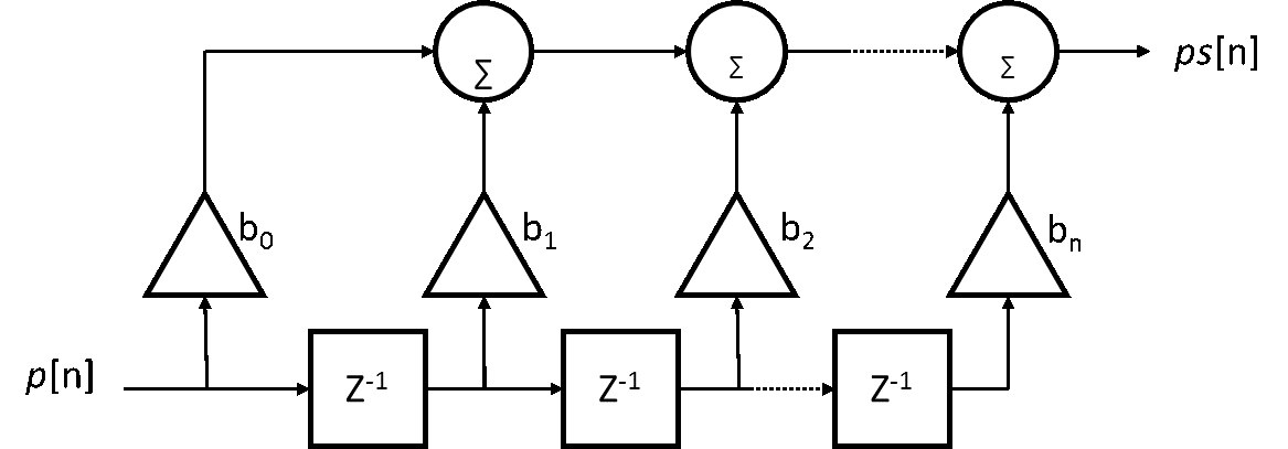 Figure 4 Finite impulse response filter
Where:
p[n]: is the input pressure reading.
Ps[n]: is the output smooth pressure value after the filter.
bi: Filter coefficient.
N: Filter order.
The FIR filter waschosen due to its stability, linearity, and simplicity. A practical analysis was performed to choose the filter in order to achieve a balance between the time required and the stability of pressure readings. While the stability of the sensor readings is enhanced by increasing the filter order, the time required to complete the smoothing filter is also increases. In real transportation task applications, the elapsed time to estimate the current robot’s floor is an essential aspect to manage since the robot must estimate its current floor, distinguish the elevator door status, and leave the elevator before the elevator door closes. Thus, a first order smoothing filter has been selected. The smoothing filter is embedded inside the microcontroller and the MBED development environment is used to program the microcontroller using the C language. Figure 5 shows the implemented flowchart for a microcontroller which starts by initializing it with the necessary setting, then collecting the pressure sensor data, applying the smoothing filter to these data with a special procedure on the first occasion to stabilize the output, and finally sending it over USB to the robot computer every 1s. Secondly, an adaptive calibration method is used to calibrate the sensor readings to the robot’s current floor before entering the elevator in order to overcome the wide variations in daily pressure readings. According to an experiment conducted over one week (the second experiment reported in the results section), the variation can reach up to approximately one hundred meters. The indoor localization method developed earlier, which is based on passive landmarks for a multi-floor environment, was utilized to identify the robot’s current floor number outside the elevator.
The calibration value is calculated as follows. Firstly, the multiple floor localization method developed earlier is used to find the current floor information outside the elevator based on the landmark ID located near the elevator. Then the pressure sensor reading is converted into the height using equation 2. The extracted height is calibrated with the current floor height to realize a constant number which is the calibration value. Then the calibration value is added to current floor height. Finally, the extracted height is compared with the height range of each floor to identify the current robot’s floor (see Figure 6 ). The reconnection function is developed to maintain a stable connection to the sensor board by continuously checking the incoming message. In the case of missing data, the serial port will close and initialize again till receiving the updated data.
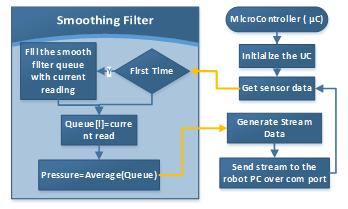 Figure 5 Microcontroller flowchart
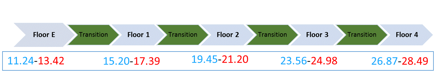 Figure 6 The Range of Height Measurements for each Floor
The MFS is embedded with the required GUI and coded with C# to handle the connection to the microcontroller; the incoming data and calibration stage are shown in Figure 7.
During a multi-floor transportation tasks, the ultrasonic sensor is used to recognize the elevator door’s status. When the destination floor matches the estimated robot’s current floor and the elevator’s door status is recognized as “open”, the robot leaves the elevator to complete the transportation task process.
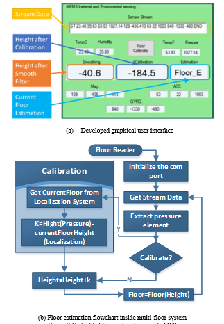 Figure 7 Embedded floor estimation inside MFS
4. Elevator Handling Error Management System
The proposed detailed robot-elevator interface control strategy is illustrated in Figure 8. The EHS classifies the error according to its appearance space as either outside or inside elevator error handling. The elevator handling system has two methods for handling outside elevator errors. If the mobile robot fails to reach the required elevator button pushing area accurately which is usually due to wheel slip, the position and orientation correction function checks the robot’s position after movement and tries to correct it three times. Next, the elevator handling system based on computer vision and an arm solution starts. After the robot has found the button’s position as X, Y, Z coordinatesthe values are then passed to the robot arm kinematic module for button pressing operation. The ultrasonic sensor is then utilized to distinguish the elevator door status. If the door is recognized as closed, the EHS controls the robot kinematic arm again to press the detected button. If previous attempts have failed, the EHS selects the AEMS over the Wi-Fi socket to open the door. If the functions listed above have failed in handling the elevator correctly, the MFS reports to the higher level controller RRC, terminates the current transportation operation, and directs the robot to the charging station.
The error handling system inside the elevator starts by monitoring whether or not the destination floor has been reached by continuously checking the current floor reader. If it does not reach the destination floor after a specified number of attempts, the MFS sends a warning alarm to the RRC to initiate the appropriate procedures. After finding the destination floor, the next stage of error handling is enabled to check the elevator door status, and another warning alarm is sent to the RRC if the door is still closed after a defined number of attempts. The final error handling maneuver is to check if the floor reached matches the required destination floor based on the landmarks installed outside the elevator. If the landmark is missing or a wrong floor number landmark is read, the error handling system returns the robot back to the elevator and chooses the destination floor again. Finally, if the robot fails to reach the destination floor after reaching the maximum allowed number of attempts, an error message is sent to the RRC. These steps are arranged as a flowchart in Figure 9.
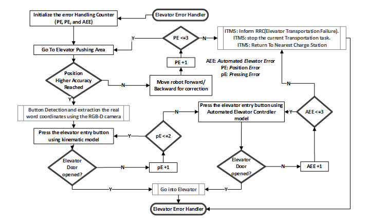 Figure 8 Outside Elevator Error Handling Flow Chart.
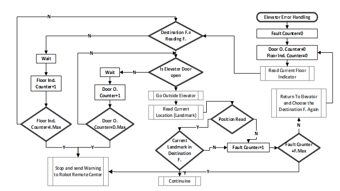 Figure 9 Inside Elevator Error Handling Flowchart
5. Results
Four sets of experiment have been performed to prove the efficiency of the developed system. The first experiment was conducted to check the stability of the pressure sensor before and after smoothing filter application. The smoothing filter was applied with different parameters to find an acceptance performance level to achieve a balance between filter performance and elapsed time. The second experiment was executed to validate the stability of atmospheric pressure readings over time. Then the integration into a real mobile robot-based transportation system was examined, and finally the system’s extension for multiple robots was verified as follows.
The IKS01A1 MEMS inertial and environmental sensor board has the pressure sensor LPS25HB. This board was attached to the STM32F411 microcontroller board as shown in Figure 10, and the developed system for data acquisition was written in the C# language. Pressure sensor readings were collected from five floors with one hundred pressure readings for each floor. The pressure sensor data before applying smoothing are shown in Figure 11. Next, the smoothing filter with first order was applied to the acquired pressure sensor readings (see Figure 12), and finally the second order smoothing filter was applied to the collected data to validate performance (see Figure 13). Table 2 shows the average and possible tolerance for pressure sensor readings before and after smoothing filter application. From Table 2, it can be seen that the oscillation of the pressure sensor readings for the same floor at different times can exceed the distance between two floors, which makes decisions about floor identification impossible. Thus, the acquired data has to be filtered, and the second order filter gives higher smoothing performance than the first order smoothing filter, but the required time can cause the robot to miss the destination. Thus the first order smoothing filter was chosen to determine the floor within an acceptable time.
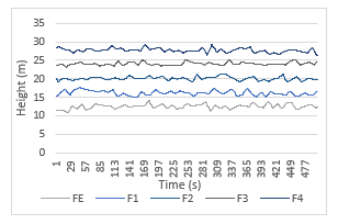 Figure 11 Pressure Raw Data
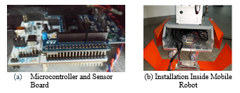 Figure 10 Floor Estimation Hardware
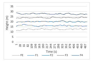 Figure 12 First Order Smoothing Filter
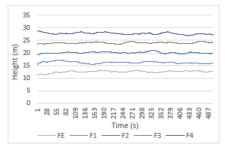 Figure 13 Second Order Smoothing Filter
Table 2 Height measurement in meter with different filter order
| Floor | Raw | First Order | Second Order | |||
| Average | +- | Average | +- | Average | +- | |
| 4 | 27.696 | 1.29 | 27.694 | 0.81 | 27.694 | 0.768 |
| 3 | 24.032 | 0.965 | 24.03 | 0.71 | 24.038 | 0.52 |
| 2 | 20.108 | 1.015 | 20.11 | 0.83 | 20.116 | 0.73 |
| 1 | 16.211 | 1.245 | 16.208 | 1.097 | 16.209 | 0.928 |
| e | 12.586 | 1.59 | 12.598 | 1.09 | 12.609 | 0.803 |
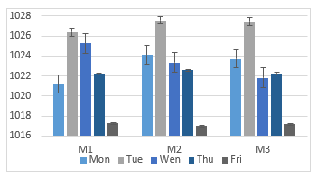 Figure 14 Daily Pressure
The second experiment was conducted to check the variance in daily pressure and the possibility of using the developed floor estimation method directly. During five working days, pressure sensor readings were taken and recorded. Three hundred readings were taken each day distributed equally among three times (morning, midday, and afternoon). From Figure 14, it can be noticed that the pressure sensor gives wide variation even on the same day, and thus the pressure data require an adaptive calibration stage.
The third set of experiments was conducted in order to evaluate the performance of the AEMS and current floor estimation technique based on the height measurement system. A transportation task between laboratories located on the second and third floors was executed one hundred times in the CELISCA building. The transportation task started from the second floor, moving to the third floor for placing and finally returning to the second floor for charging. The AEMS calls the elevator to the robot’s current floor for it to move to the third floor.
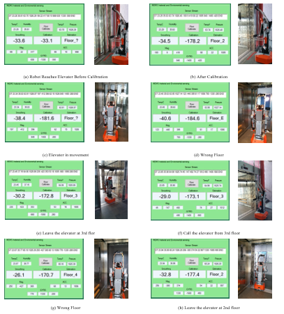 Figure 15 Transportation Experiment
Inside the elevator, the ground floor was chosen by another passenger before the robot called the 3rd floor. This stage was included to examine the current floor estimation method. At first, the elevator controller directed the elevator to the ground floor and the elevator’s door opens. At this stage, the robot stays in the elevator since the detected current floor estimation does not match the destination floor. The robot waits until the detected current floor matches the destination floor and the elevator’s door is recognized as open. Also, the same procedures were repeated when the robot had to return to the 2nd floor for charging, where the 4th floor was selected by another passenger before the robot called its destination. Each time, the robot succeeding in leaving the elevator at the correct floor. The developed system’s stability and reliability is proven with a 100% success rate. Figure 15 demonstrates the experiment steps in detail.
The final experiment was executed to validate the possibility of extending the method of current floor estimation based on the height measurement system to other mobile robots. The same kind of sensor board with the same processing stages (a one-point calibration stage, first order FIR smoothing filter, and an adaptive calibration stage) was embedded for three other mobile robots. The procedures used in the third experiment were repeated ten times for each robot to validate their ability to estimate the current floor. Each robot succeeded in estimating its current floor inside the elevator without any change needed in the sensor board or the processing stages.
6. Conclusion
In this paper, a secured method for the elevator handling system based automated elevator is presented. To handle the elevator, four main operations should be considered which are elevator requesting, destination floor calling, current floor estimation, and elevator’s door status recognition. The automated elevator handling system mainly consists of WISE 4060 ADAM modules. A Wi-Fi socket is established to connect the automated elevator management system with the ADAM module. This module can call the elevator to the current floor and request the current floor when the robot enters the elevator. However, this module does not provide any feedback about the robot’s current floor inside the elevator which may make the robot lose its way to the destination. Thus, an innovative and stable current floor estimation based on a height measurement system is presented. The height measurement system consists of the LPS25HB pressure sensor attached to the STM32F411 microcontroller. To utilize the pressure sensor as a height measurement system many aspects must be considered which as follows: firstly, a soldering drift, which is defined as the difference between the accuracy of the sensor before and after soldering. A one-step calibration stage is employed to solve this problem. This technique compares the pressure sensor reading after soldering with a precision barometer. The difference is added to each pressure reading. Secondly, the oscillation of the output signal and the wide variations in barometric readings during the week. The first order FIR smoothing filter is employed to overcome the oscillation in the pressure sensor output signal while an adaptive calibration stage is used to handle the wide variation. The ultrasonic sensor is used to recognize the elevator’s door stats. An error management system is developed to guarantee a secured elevator handling system. A series of experiments has been conducted to evaluate the variation in the pressure sensor readings and to validate the performance of the presented systems. The results of the experiments prove the efficiency of the automated elevator management sensor and robot’s current floor inside the elevator with a success rate reaches to 100% for each.
Conflict of Interest
The authors declare no conflict of interest.
Acknowledgment
The authors would like to thank the Ministry of Higher Education and Scientific Research in Iraq for the scholarship provided by Mosul University, as well as the Federal Ministry of Education and Research Germany for the financial support (FKZ: 03Z1KN11, 03Z1KI1).
- A. A. Abdulla, H. Liu, N. Stoll, and K. Thurow, “An automated elevator management and multi-floor estimation for indoor mobile robot transportation based on a pressure sensor,” in 2016 17th International Conference on Mechatronics – Mechatronika (ME), 2016, pp. 1–7.
- A. V. Savkin and C. Wang, “A framework for safe assisted navigation of semi-autonomous vehicles among moving and steady obstacles,” Robotica, vol. 35, no. 5, pp. 981–1005, 2017.
- V. Subbian, J. J. Ratcliff, J. M. Meunier, J. J. Korfhagen, F. R. Beyette Jr., and G. J. Shaw, “Integration of new technology for research in the emergency department: Feasibility of deploying a robotic assessment tool for mild traumatic brain injury evaluation,” IEEE J. Transl. Eng. Health Med., vol. 3, 2015.
- D. Leidner, A. Dietrich, M. Beetz, and A. Albu-Schäffer, “Knowledge-enabled parameterization of whole-body control strategies for compliant service robots,” Auton. Robots, vol. 40, no. 3, pp. 519–536, Mar. 2016.
- A. Ravankar, A. A. Ravankar, Y. Kobayashi, and T. Emaru, “On a bio-inspired hybrid pheromone signalling for efficient map exploration of multiple mobile service robots,” Artif. Life Robot., vol. 21, no. 2, pp. 221–231, Jun. 2016.
- J. Zhang, D. Chen, S. Wang, X. Hu, and D. Wang, “Design and experiment of four-wheel independent steering driving and control system for agricultural wheeled robot,” Nongye Gongcheng XuebaoTransactions Chin. Soc. Agric. Eng., vol. 31, no. 18, pp. 63–70, 2015.
- J. Bell, B. A. MacDonald, H. S. Ahn, and A. J. Scarfe, “An Analysis of Automated Guided Vehicle Standards to Inform the Development of Mobile Orchard Robots,” IFAC-Pap., vol. 49, no. 16, pp. 475–480, Jan. 2016.
- L. Cragg, H. Hu, and N. Voelker, “Modularity and mobility of distributed control software for networked mobile robots,” Springer Tracts Adv. Robot., vol. 30, pp. 459–484, 2007.
- B. Siemiatkowska, B. Hrasymowicz-Boggio, and M. Wisniowski, “The application of mobile robots for building safety control,” J. Autom. Mob. Robot. Intell. Syst., vol. 10, no. 2, pp. 9–14, 2016.
- D. Schmidt, C. Hillenbrand, and K. Berns, “Omnidirectional locomotion and traction control of the wheel-driven, wall-climbing robot, ” Robotica, vol. 29, no. 7, pp. 991–1003, Dec. 2011.
- M. Yim, K. Roufas, D. Duff, Y. Zhang, C. Eldershaw, and S. Homans, “Modular Reconfigurable Robots in Space Applications,” Auton. Robots, vol. 14, no. 2–3, pp. 225–237, Mar. 2003.
- D. Culler and J. Long, “A Prototype Smart Materials Warehouse Application Implemented Using Custom Mobile Robots and Open Source Vision Technology Developed Using EmguCV,” Procedia Manuf., vol. 5, pp. 1092–1106, Jan. 2016.
- K. Kashiwazaki et al., “A car transportation system using multiple mobile robots: iCART II,” in 2011 IEEE/RSJ International Conference on Intelligent Robots and Systems, 2011, pp. 4593–4600.
- S.-N. Yu, J.-H. Jang, D.-H. Kim, J.-Y. Lee, and C.-S. Han, “A gait-assistive mobile robot based on a body weight support and autonomous path tracking system,” Proc. Inst. Mech. Eng. Part C J. Mech. Eng. Sci., vol. 226, no. 3, pp. 828–841, Mar. 2012.
- I.-H. Kuo, C. Jayawardena, E. Broadbent, and B. A. MacDonald, “Multidisciplinary Design Approach for Implementation of Interactive Services,” Int. J. Soc. Robot., vol. 3, no. 4, pp. 443–456, Nov. 2011.
- T. He, M. Bando, M. Guarnieri, and S. Hirose, “The development of an autonomous robot system for patrolling in multi-floor structured environment,” Int. J. Autom. Technol., vol. 6, no. 1, pp. 13–21, 2012.
- Chen, L.-K. and Hsiao, M.-Y., “Control of service robot by integration of multiple intermittent sensors,” in AMPT 2013, Taipei; Taiwan, 2014, vol. 939, pp. 609–614.
- K. Maneerat, C. Prommak, and K. Kaemarungsi, “Floor estimation algorithm for wireless indoor multi-story positioning systems,” in 2014 11th International Conference on Electrical Engineering/Electronics, Computer, Telecommunications and Information Technology (ECTI-CON), 2014, pp. 1–5.
- L. Chen, B. Sun, and X. Chang, “MS5534B Pressure Sensor and Its Height Measurement Applications,” in 2011 International Conference on Information Technology, Computer Engineering and Management Sciences (ICM), 2011, vol. 1, pp. 56–59.
- H. Xia, X. Wang, Y. Qiao, J. Jian, and Y. Chang, “Using Multiple Barometers to Detect the Floor Location of Smart Phones with Built-in Barometric Sensors for Indoor Positioning,” Sensors, vol. 15, no. 4, pp. 7857–7877, Mar. 2015.
- K. Frank, E. M. Diaz, P. Robertson, and F. J. F. Sánchez, “Bayesian recognition of safety relevant motion activities with inertial sensors and barometer,” in 2014 IEEE/ION Position, Location and Navigation Symposium – PLANS 2014, 2014, pp. 174–184.
- A. A. Abdulla, H. Liu, N. Stoll, and K. Thurow, “A New Robust Method for Mobile Robot Multifloor Navigation in Distributed Life Science Laboratories,” J. Control Sci. Eng., vol. 2016, Jul. 2016.
- A. A. Abdulla, H. Liu, N. Stoll, and K. Thurow, “A Robust Method for Elevator Operation in Semioutdoor Environment for Mobile Robot Transportation System in Life Science Laboratories,” in International Conference on Intelligent Engineering Systems (INES), 2016 IEEE International, Budapest, Hungary, 2016, pp. 45–50.
- M. M. Ali, H. Liu, R. Stoll, and K. Thurow, “Intelligent Arm Manipulation System in Life Science Labs Using H20 Mobile Robot and Kinect Sensor,” in IEEE International Conference on Intelligent Systems (IS’16), Sofia, Bulgaria, 2016, pp. 382–387.