A Modified Patch Antenna with Square-Open Loop Resonator Slot for Improved Bandwidth Performance in WiFi Applications
A Modified Patch Antenna with Square-Open Loop Resonator Slot for Improved Bandwidth Performance in WiFi Applications
Volume 2, Issue 3, Page No 1467-1471, 2017
Author’s Name: Rida Gadhafia), Mihai Sanduleanu
View Affiliations
Department of Electrical And Computer Engineering, Masdar Institute, A part of Khalifa University of Science and Technology, 54224, United Arab Emirates
a)Author to whom correspondence should be addressed. E-mail: rgadhafi@masdar.ac.ae
Adv. Sci. Technol. Eng. Syst. J. 2(3), 1467-1471 (2017); ![]() DOI: 10.25046/aj0203183
DOI: 10.25046/aj0203183
Keywords: Square patch antenna, Open loop resonator slot, Bandwidth enhancement

Export Citations
A novel, modified square patch antenna with square open loop resonator slot, operating at 5.5 GHz, for improved bandwidth performance is proposed in this article. A complementary square open loop resonator is introduced on the patch to enhance the bandwidth more than twice that of the conventional square patch antenna operating at the same frequency. A prototype of the antenna operating at 5.5 GHz is designed and fabricated. Results show that 2:1 VSWR bandwidth of the antenna is 7% whereas the conventional square patch antenna offers only 3% bandwidth. The proposed antenna has a compact size of 1.9 cm x 2 cm. It offers a uniform gain of 4.25 dB and a directivity of 6.1 dB at the frequency of operation.
Received: 29 May 2017, Accepted: 21 July 2017, Published Online: 10 August 2017
1. Introduction
Owing to their small size, low cost/weight, conformability, and ease of manufacturing, microstrip patch antennas are chosen in many designs applied to standard mobile services and satellite systems [1-2]. However, the main barrier of considering these antenna types for a large range of applications is related to their limited bandwidth [3-5]. The ‘Long Term Evolution’ (LTE) and ‘Long Term Evolution-Advanced’ (LTE-A) new standards for 4G, require large bandwidths (up to 200MHz) and it is expected, that newer standards will require even higher bandwidths [6-9]. In that respect, several techniques were discussed in the literature, for bandwidth improvement, including changing the feed type, stacking the patch, modifying the geometry of the patch, and changing the feed location [10-14]. Each method has its own trade-offs, particularly involving the size of the antenna. The use of resonant slots for increasing the bandwidth was proposed in [1]. The resonant frequency of the slot could be chosen in such a way that its operating frequency is different than the resonant frequency of the conventional antenna. This leads to the staggering of two frequencies which, in turn, will increase the bandwidth significantly.
This paper is an extension of work originally presented in the International Conference on Electronic Devices, Systems and Applications [15]. In this extended version, the design of novel square patch antenna with a complementary square open loop resonator (C-SOLR) is explained with the support of measurement results. A square patch antenna with and without C-SOLR is explained. In the proposed design, C-SOLR utilizes proximity coupling. At first, a patch antenna without C-SOLR operating at 5.5 GHz is designed. C-SOLR can reject the corresponding frequency enabling bandwidth enhancement. C-SOLR has been introduced on the patch without affecting the radiation characteristics of the antenna. The proposed antenna offers 400 MHz, 2:1 VSWR bandwidth which is significantly higher than that of the bandwidth obtained by other techniques like changing the feed of the patch proposed in [2], [14]. The proposed antenna offers simulated directivity and gain of 6.1 dB and 4.25 dB respectively.
The remaining sections of this article is organized as follows: Section II explains the design of C-SOLR antenna; Section III, presents simulation results followed by the measurement validation. Finally, the paper is concluded in Section IV.
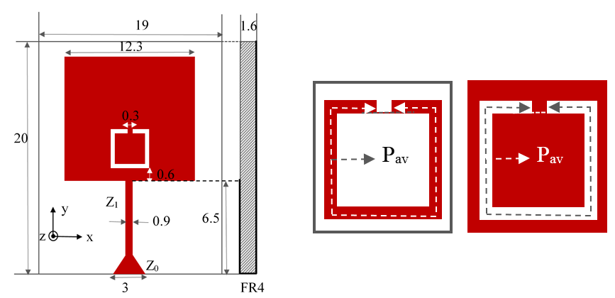 Figure 1: Geometry of the antenna and the classical loop resonator. a) antenna with C-SOLR. (All dimensions are in mm). b) Square open loop resonator (S-OLR), c) Complementary Square open loop resonator (C-SOLR)
2. Antenna Design
The geometry of the proposed antenna is shown in Figure 1 (a). The substrate used is FR-4 with relative permittivity of 4.4, loss tangent of 0.02 and thickness of 1.6 mm. The proposed antenna is a square patch with a complementary square open loop resonator (Figure 1 (c)). The square patch used in this design is the conventional square patch antenna. In order to achieve the broadband operation of the antenna, a resonating slot is introduced. Square open loop resonator (S-OLR) has been chosen here because of their compact size and ease of design [15]. S-OLR can resonate at half the frequency as that of the closed loop resonator with the same dimension. S-OLR are also considered as a microstrip line, loaded with folded open stubs at both ends. Figure 1(b) shows the structure of classical square open loop resonator (S-OLR). The fundamental resonance frequency f0 of S-OLR can be given by:
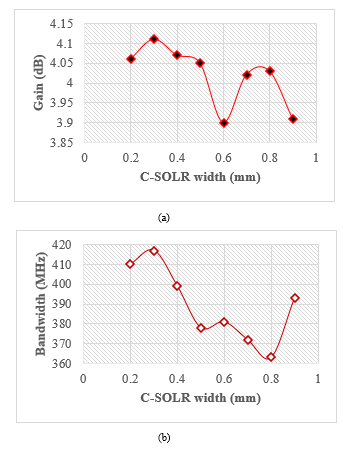
In (1), Pav is the average perimeter, s is the gap between the open ends and εeff is the effective permittivity of the substrate [16]. Inspired by its compactness, we are introducing the ‘negative square open loop resonator’ which can also be called ‘complementary square open loop resonator (C-SOLR) in analogy to the concept of complementary split ring resonator (CSRR) (see Figure 1(c)). From simulation study, we have observed that C-SOLR behavior is governed by eq. (1). When C-SOLR is coupled to a transmission line, the wave propagation is rejected in the vicinity of the resonant frequency. This property of the C-SOLR is exploited here which enables a larger bandwidth compared to the antenna without C-SOLR. The antenna has a compact dimension of 19 mm x 20 mm. The width of the square patch (Wp) is 12.3 mm and can resonate at 5.5 GHz. Ansoft High Frequency Structure Simulator (HFSS) is used to perform simulations. The optimum gap g between the C-SOLR and feed line uses proximity coupling A parametric study has been done and the optimum gap is found to be 0.6 mm. This, ensures better coupling and impedance matching as shown in Figure 2. The square patch is matched to a transmission line of characteristic impedance Z0 (50 Ω line) by using a quarter wavelength transmission line transformer of characteristics impedance Z1 as shown in Figure 1 (a). The optimum width of the quarter wavelength transmission line is WT=0.9 mm. The 50 Ω line is mitered to alleviate the small mismatch between the high and low impedance line by chopping off the small amount of capacitance introduced due to the sudden transition from the high impedance to low impedance line. Thus, it can also reduce the unwanted reflections due to the abrupt change. The width of the C-SOLR is determined from a parametric study and the optimum value is found to be 0.3 mm for better impedance matching and gain as shown in Figure 3 (a) & (b). Table I summarizes the optimized parameters of the C-SOLR antenna.
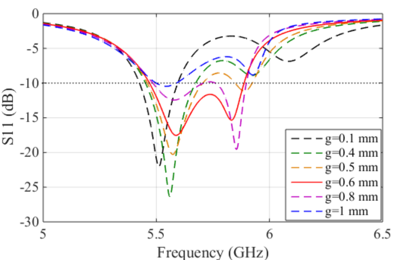 Figure. 2: Influence of coupling gap g on the reflection coefficient.
|
|
3. Results and Discussion
Simulation and measurement of proposed antenna is discussed in this section. Antenna measurements were conducted using Agilent Network Analyzer (PNA-X N5242A).
Firstly, a square patch antenna without resonating slot has been simulated. Figure 4 (a) shows the simulated S-parameters of the square patch antenna without any slot. As shown, it produces a narrow bandwidth of 170 MHz. Figure 4 (b) shows the corresponding E-plane and H-plane pattern. As can be seen, the patterns are unidirectional. The square patch antenna offers a gain and directivity of 4.3 dB and 6.1 dB respectively.
|
Table I Optimal parameter values of the proposed antenna
|
By properly placing the C-SOLR on the patch, the prototype has been transformed to the C-SOLR patch antenna as depicted in Figure 1(a). From simulations it was found that the parameter g places an important role in the impedance matching and coupling to the feed line as well. Figure 5 shows the influence of g on VSWR bandwidth. Thus, the optimum value of g has been found as 0.6 mm (see Table I). The resonance frequency of the C-SOLR has been chosen as a frequency near to the resonance frequency of the square patch without any slot.
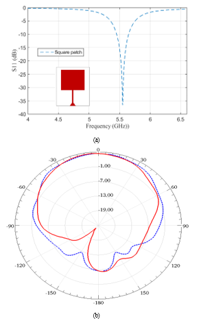 Figure 4: Simulated reflection and 2-D radiation characteristics of a conventional patch antenna. a) simulated S-parameters, b) E-plane (solid line) and H-plane (dashed line) pattern.
The designed antennas were fabricated on standard FR4 substrate with relative permittivity of 4.6 and a dielectric height of 1.6 mm. Figure 6 (a) shows the fabricated antenna. The simulated and measured reflection characteristics are depicted in Figure 6 (b). As shown in the figure, they are in good agreement. From simulations, we have observed that C-SOLR operates in accordance with eq. (1). Moreover, more than twice bandwidth of the conventional antenna can be obtained using the C-SOLR antenna. The proposed antenna offers 7%, 2:1 VSWR bandwidth whereas, the conventional antenna offers only 3%, 2:1 VSWR bandwidth.
Figure 7 shows the 2-Dimensional radiation characteristics of the proposed antenna. The antenna provides a directive radiation pattern towards the patch surface. Notably, the C-SOLR has been introduced without disturbing the radiation characteristics of the antenna. This is the main advantage of our proposed methodology.
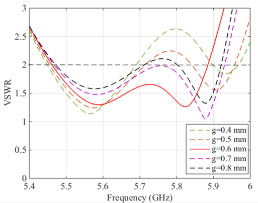 Figure 5: Influence of gap g on VSWR bandwidth.
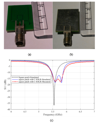 Figure 6: Fabricated antenna and corresponding simulated and measured reflection coefficient, a) antenna front view, b)antenna rear view, c) reflection coefficient.
Thus, the slotted SOLR antenna offers almost the same gain and directivity as a conventional square patch antenna with 4.25 dB gain and 6.1 dB directivity as shown in Figure 8. From simulations, the proposed antenna offers a uniform gain and directivity. In Figure 8, the gain tend to decrease above 5.87 GHz and indicates the appearance of cross polarized component as a consequence of using the C-SOLR structure.
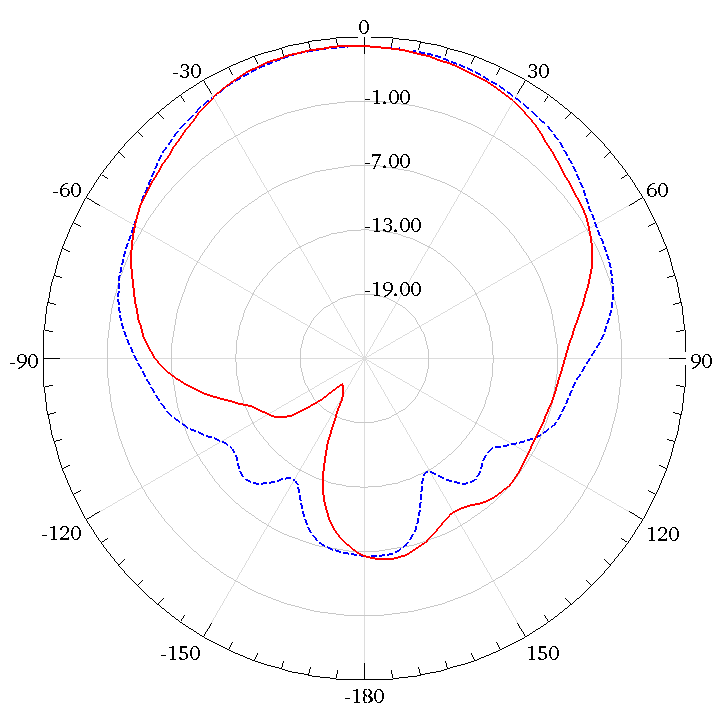 Figure. 7: Simulated 2-D radiation characteristics of C-SOLR patch antenna. E-plane (solid line) and H-plane (dashed line) pattern.
Thus, if we didn’t chose the optimum frequency for the C-SOLR, this cross-polarizing component will appear inside the band of interest, causing a non-uniform gain. The uniform gain is an advantage of SOLR in comparison to a rectangular loop resonator in which, the longitudinal arm of the resonator produces the cross polarized component within the band of interest. The rectangular loop resonator causes a non-uniform gain but has comparable bandwidth with that of the SOLR.
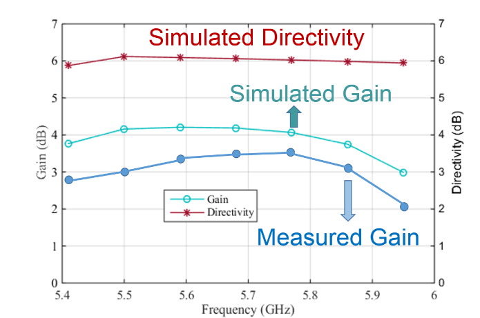 Figure.8: Simulated/measured gain and directivity of C-SOLR patch antenna.
The power transfer measurement of the proposed antenna has also been conducted as depicted in Figure 9 (a). Two identical antennas separated with a distance d were connected to the two ports of the Network Analyzer and corresponding S21 was measured. The power receiving capability of the antenna was tested for different distances. As shown in Figure 9 (b), the magnitude of power level is decreasing with increasing the distance. The measurement was conducted for a range of d from 1.5 cm to 3.8 cm.
4. Conclusion
The presented article proposes a novel C-SOLR patch antenna with enhanced bandwidth with the support of measurement. A proximity coupled complementary square open loop resonator is placed on the patch. C-SOLR rejects this frequency and, as a result, the bandwidth is enhanced. Results proves that C-SOLR antenna offers more than twice the bandwidth of a conventional square patch antenna, without disturbing the radiation characteristics. The proposed antenna offers the same uniform gain and directivity as that of the square patch antenna, as well. It can operate from 5.47 GHz- 5.87 GHz and could be used for WiFi applications. The antenna can be easily redesigned for another frequencies, e.g. to meet the extensive bandwidth requirement of 200 MHz for LTE standards applied to 4G systems.
- M.M. Honari, A. Abdipour, G. Moradi, “Bandwidth and Gain Enhancement of an Aperture Antenna with Modified Ring Patch,” IEEE Antennas and Wireless Propagation Letters, vol. 10, pp. 1413-1416, 2011.
- A.G. Koutinos, G.A. Ioannspoulos, M.T. Chryssomallis, and G.A. Kyriacou, “A Dual Feed Rectangular Patch Antenna for Bandwidth Enhancement”, 10th Loughborough Antennas and Propagation Conference(LAPC), UK, pp.698-702, November, 2014.
- K. Mandal, S. Sarkar, and P. P. Sarkar, “Bandwidth enhancement of microstrip antenna by staggering effect,”Microw. Opt. Technol. Lett.,
vol. 53, pp. 2446–2447, 2011. - X. L. Bao and M. J. Ammann, “Small patch/slot antenna with 53% input impedance bandwidth,” Electron. Lett. vol. 43, pp. 146–147, 2007.
- S.L.S.Yang, A.A.Kishk, and K.F. Lee, “Frequency reconfigurable U-slot microstrp patch antenna, “IEEE Antennas Wireless Propaga. Lette. Vol.7,pp. 127-129, 2008.
- S. Capora Dell Bario, M. Pelosi, and G.F. Pedersen, “On the effieciency of reconfigurable high-Q antennas for 4G standars,”Electronic Letters, vol.48, issue.16, pp. 982-983, Aug.2012
- P. Bahramzy, O.Jagielski, S. Svendsen, P. Olesen, G.F. Pedersen, “Aspects of high-Q tunable antennas and their deployment for 4-G mobile Mobile Communications”, IEEE Antennas and Propagation Magazine, vol. 58, issue. 4, pp. 70-81, 2016.
- S.F. Roslan, M.R. Kamarudin, M. Khalily, and M. H. Jamaluddin, “An MIMO rectangular dielectric resonator antenna for 4G applications,” IEEE antennas and wireless propagation letters, vol. 13, pp. 321-324, 2014.
- F.M. Caimi, “Antenna Design challenges for 4G,” IEEE Wireless Communications, vol.18, issue.6, pp. 4-5, 2011.
- Nasimuddin and Z. N. Chen, “Wideband Microstrip Antennas with Sandwich substrate,” Microw., Antennas Propag., vol. 2, pp. 538–546, 2008.
- C.-H. Lai, T.-Y. Han, and T.-R. Chen, “Broadband aperture- coupled microstrip antennas with low cross polarization and back radiation,” Prog. Electromagn. Res. Lett., vol. 5, pp. 187–197, 2008.
- J. S. Chen and K. L. Wong, “A single-layer dual-frequency rectangular Microstrip patch antenna using a single probe feed”, Microwave Opt. Technol. Lett. Vol.11, pp. 83–84, Feb. 5, 1996.
- M. T.Ali,N.Nordin, N. Ya’acob, andM.N. M. Tan, “Design of wideband microstrip patch antenna using L probe fed at 2.6 GHz,” in Proc. ICCCE, 2012, pp. 961–965.
- A.G. Koutinos, G.A. Ioannspoulos, P.K. Gkonis, M.T. Chryssomallis, and G.A. Kyriacou, “A Novel Quadruple-Fed Rectangular Patch Antenna with Improved Bandwidth Performance”, 11th Loughborough Antennas and Propagation Conference(LAPC), UK, November 2015.
- J. Hong and M. Lancaster, “Couplings of microostrip square open-loop resonators for cross-coupled planar micorwave filters,” IEEE Transcations on Microwave Theory and Techniques, vol. 44, no.12, pp.2099-2109, December 1996.
- K. Chang, and L-H.Hsieh, “Microwave Ring Circuits and Related Structures,”Second Edition, Wiley Series in Microwave and optical Engineering, 2004.