Two-axis Gimbal with Passive Revolute Joints for Motion Isolation of a Stabilizing Mechanism
Two-axis Gimbal with Passive Revolute Joints for Motion Isolation of a Stabilizing Mechanism
Volume 2, Issue 3, Page No 1401-1412, 2017
Author’s Name: Erick Moya1, a), Keizo Araki2, Masaki Okada2, Akira Mizuno2, Kenjiro Tadakuma3, Riichiro Tadakuma1
View Affiliations
1Department of Mechanical Systems Engineering, Yamagata University, 992-8510, Japan
2Equos Research, 101-0021, Japan
3Department of Mechanical and Aerospace Engineering, Tohoku University, 980-8579, Japan
a)Author to whom correspondence should be addressed. E-mail: tym80862@st.yamagata-u.ac.jp
Adv. Sci. Technol. Eng. Syst. J. 2(3), 1401-1412 (2017); ![]() DOI: 10.25046/aj0203176
DOI: 10.25046/aj0203176
Keywords: intertially stabilized platform, mass stabilization, omnidirectional gear, passive gimbal

Export Citations
Energy efficiency is a salient design consideration for stabilization mechanisms when assembled on a battery-powered vehicle. In this paper we study the implementation of a two-axis gimbal with passive revolute joints for motion isolation of an inertially stabilized platform (ISP) mounted on a host vehicle. The objective is for the ISP to maintain a steady line of sight (LOS) of a payload placed in an arbitrary position on the ISP workspace by performing mass stabilization. The proposed method eliminates the need to operate gimbal motors throughout the operation of the host vehicle, stabilizing the platform LOS by relying on the gimbal passive joints acting as suspension to isolate the ISP from disturbances imparted by the host vehicle. We describe the principle of operation and a prototype of the proposed stabilizing mechanism is presented.
Received: 31 May 2017, Accepted: 20 July 2017, Published Online: 05 August 2017
1. Introduction
An inertially stabilized platform consists of a gimballed electromechanical system that maintains a steady line of sight (LOS) of a payload (imaging instrument, communication instrument, sensor, etc.) with respect to an inertial reference frame. The control system adjusts the gimbal orientation angle to compensate for the changes in orientation of the host vehicle on which it is mounted. The angular motion of the host vehicle is measured with an inertial measurement unit (IMU). The stabilizing algorithm calculates the necessary coordinate frame transformations in order to derive the target orientation of the gimbal in inertial space for the platform to hold its line of sight.
For the payload to maintain its line of sight, the stabilizing system must have a quick response time. Moreover, in conventional applications of gimballed stabilization, the system must actively drive the gimbal actuators throughout the operation of the host vehicle to compensate its changes in orientation and to reject other disturbances. This turns out to be computationally expensive, since the required kinematic calculations and the calculations of target angular velocities of the gimbal motors have to be performed fast enough not to impose a lag in response time of the system. Perhaps more importantly, the active gimbal compensation throughout the operation of the vehicle demands a high consumption of power.
In this research, we study the implementation of a two-axis gimbal with unactuated freely rotating joints for disturbance isolation of an inertially stabilized platform (ISP). A payload is placed by a user in an arbitrary position within the ISP workspace, and the line of sight stabilization of the payload is achieved by displacing a counterweight horizontally and vertically to adjust the center of gravity (COG) of the payload-counterweight system to be at the crossing point of the passive gimbal rotation axes. As a result, undesired moments of inertia applied to the platform by external disturbances are eliminated. The passive gimbal joints act as a suspension that decouples the host vehicle chassis from the ISP, isolating it from disturbances and keeping the payload’s orientation stationary in inertial space.
2. Balancing Principle
The work presented in this paper is an extension of the stabilization method originally presented in IEEE SII2016 [1]. In the present work, we first discuss the method of elimination of moments of inertia to isolate the payload from external disturbance. We next discuss a method to calculate the position of the payload COG on the surface of the platform and present a theoretical framework to calculate the height of the payload COG by measuring the roll and pitch inclination angles of the passive gimbal. Finally, we present the results of fundamental experiments with the second prototype to evaluate the mechanism.
The aim of the stabilizing mechanism discussed in this paper is to keep a steady line of sight of a payload of arbitrary weight within the load capacity specifications of the mechanism, and with arbitrary mass distribution, placed in an arbitrary position on the stabilized platform’s workspace. To accomplish this by performing mass stabilization it is therefore necessary to measure the payload weight, and to calculate the position of the center of gravity of the payload [2, 3]. With this information about the payload, the three-dimensional target position of the counterweight is calculated to perform mass-stabilization.
Due to the freely rotating joints of the gimbal, placing a payload on the platform in a position offset from the vertical axis of symmetry of the ISP induces a torque on the passive gimbal’s axes; this results in the inclination of the platform about the gimbal axes. The stabilizing mechanism aligns the orientation of a payload with respect to the inertial reference frame by adjusting the horizontal and vertical position of a counterweight. An XY Stage mechanism displaces the counterweight center of gravity horizontally on the x-y plane and a Z Stage displaces the counterweight vertically along the z axis. The position of counterweight is adjusted to locate the center of gravity of the payload-counterweight system at the crossing point of the gimbal rotation axes.
2.1. Static Balance: Gravity
Balance on roll axis: the offset position of the payload with respect to the platform’s vertical axis of symmetry on the y-z plane induces a torque on the passive roll axis of the gimbal due to gravity, resulting in an inclination angle σ of the gimbal about its roll axis of rotation, as illustrated in Figure 1. To compensate the torque induced by the payload, the horizontal position of the counterweight is displaced along the y axis with the Y Stage up to position to induce a torque with the same magnitude and opposite direction. For static balance on the roll axis of a payload with weight and counterweight with weight , the position of the counterweight on the y axis must satisfy (1). This places the center of gravity of the payload-counterweight system on the vertical axis of symmetry of the inertially stabilized platform on the y-z plane as illustrated in Figure 2.
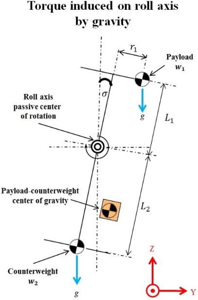 Figure 1. Inclination of the passive gimbal about the roll axis due to load unbalance against gravity on the y axis.
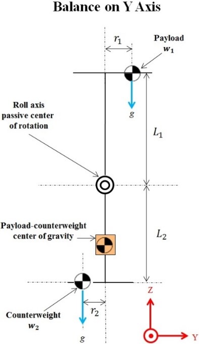 Figure 2. Static balance on the y axis against gravity provided by the displacement of the counterweight with the Y Stage.
Balance on pitch axis: the offset position of the payload with respect to the platform’s vertical axis of symmetry on the x-z plane induces a torque on the passive pitch axis of the passive gimbal due to gravity, resulting in an inclination angle of the gimbal about its pitch axis of rotation, as illustrated in Figure 3. The horizontal position of the counterweight is displaced along the x axis with the X Stage to position , which for static balance must satisfy (2). This places the center of gravity of the payload-counterweight system on the vertical axis of symmetry of the inertially stabilized platform on the x-z plane, as illustrated in Figure 4.
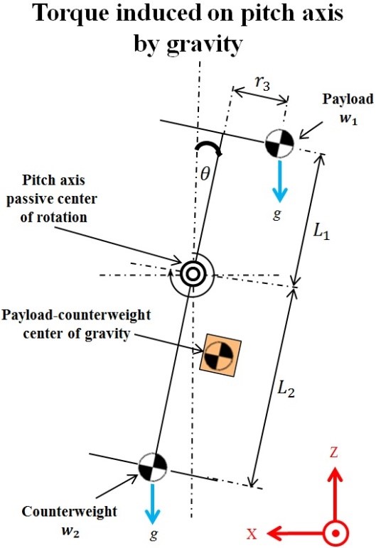 Figure 3. Inclination of the passive gimbal about the pitch axis due to load unbalance against gravity on the x axis.
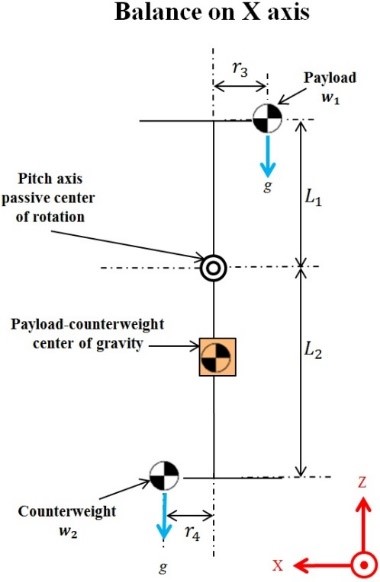 Figure 4. Static balance on the x axis against gravity provided by the displacement of the counterweight by the X Stage.
2.2. Static Balance: Disturbances by Host Vehicle
Accelerations of the host vehicle also induce torque on the passive gimbal. Depending on the direction of motion of the host vehicle, this torque is induced on either the pitch axis of the gimbal, the roll axis of the gimbal, or both. Figure 5 illustrates the inclination of the passive gimbal due to a horizontal acceleration a of the host vehicle along the x axis of the stabilizing mechanism, inducing a toque on the pitch axis of the gimbal.
To eliminate the torque induced on the passive gimbal due to accelerations of the host vehicle, the vertical position of the counterweight is displaced along the z axis with the Z Stage. For static balance the along the z axis of a payload with weight and counterweight with weight , the distance from the gimbal axis of rotation to the counterweight must satisfy (3)
where is the distance from the gimbal axis of rotation to the ISP. After the center of gravity of the payload-counterweight system is displaced horizontally by the XY Stage to place it on the vertical axis of symmetry of the gimbal, the vertical displacement along the z axis places the center of gravity of the payload-counterweight system on the crossing point of the passive gimbal rotation axes, as illustrated in Figure 6.
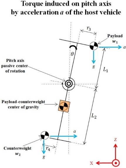 Figure 5. Inclination of the passive gimbal about the pitch axis due to load unbalance against the acceleration of the host vehicle.
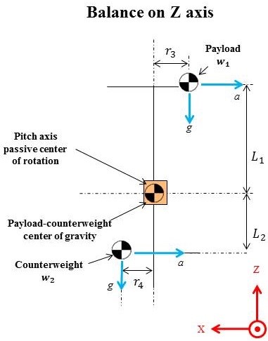 Figure 6. Static balance on z axis against host vehicle acceleration provided by the displacement of the Z Stage.
3. Components of the Stabilizing Mechanism
Figure 7 illustrates the components of the proposed stabilizing mechanism. The stabilizing mechanism consists of an XY Stage mechanism with omnidirectional driving gear [4] located below the centers of rotation of the two-axis passive gimbal. The XY Stage acts as counterweight, with adjustable position along the x and y axes. The XY Stage/Counterweight is mounted onto the Z Stage that adjusts its vertical position along the z axis. The stabilized platform is located above the centers of rotation of the passive gimbal roll and pitch axes.
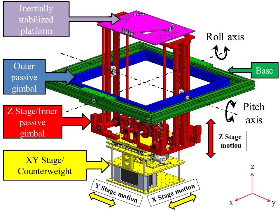 Figure 7. Stabilizing mechanism with passive two-axis gimbal.
The payload weight and the position of its COG on the surface of the ISP are measured with three CZL204E strain gauge load cells located on the platform. We propose the calculation of the height of the payload COG by measuring the roll and pitch inclination angles of the passive gimbal caused by the placement of the payload on the ISP. The passive gimbal’s roll and pitch inclination angles are measured with a SEN-10736 inertial measurement unit onboard the inner gimbal of the stabilizing mechanism [5]. The proposed method for calculating the three dimensional position of the payload COG is discussed in chapter 4. Figure 8 illustrates the stabilizing mechanism mounted on the omnidirectional host vehicle.
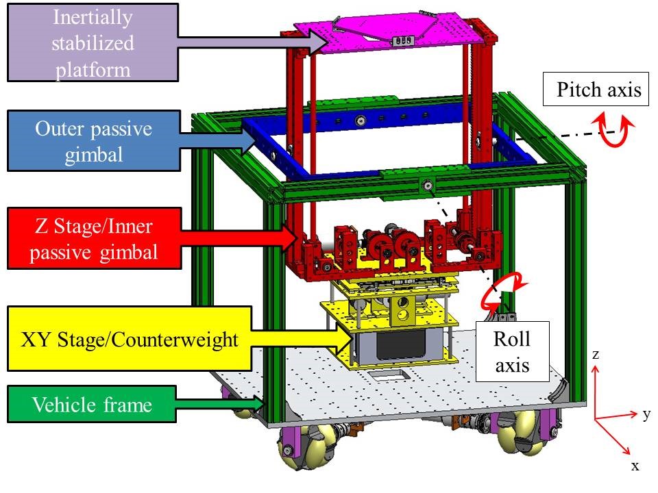 Figure 8. Stabilizing mechanism on the omnidirectional host vehicle.
4. Calculation of the Position of the Payload Center of Gravity on the Inertially Stabilized Platform
In this chapter we discuss the method of calculating the position of the payload’s center of gravity (COG) in three dimensions once it has been placed on the inertially stabilized platform. We first describe the coordinate frame assignments to the system, we next describe the method to calculate the position of the payload COG on the surface of the platform ((x,y) coordinates of the payload COG on the surface of the platform) employing the multiple-point weighing method [6]. Finally, we propose a method to calculate the height of the payload COG from the platform surface (z coordinate of the payload COG from the surface of the platform) by exploiting the passive nature of the two-axis gimbal.
The algorithm to calculate the position of the payload center of gravity in three dimensions is the following:
- Assign three coordinate frames on the stabilizing mechanism. A coordinate frame as the reference frame, a coordinate frame on the surface of the ISP, and a coordinate frame on the counterweight.
- Measure the weight of the payload and calculate the horizontal position of its COG on the platform’s surface (on ISP coordinate frame ) after the payload has been placed on the platform by the user.
- Measure the roll and pitch inclination angles of the passive gimbal caused by the placement of the payload on the ISP surface. Then describe the position of the inclined ISP and the payload COG with respect to the reference frame .
- Define a cross-sectional plane in which both the pitch and roll inclination angles of the ISP are implicit.
- Describe the position of the inclined ISP and payload COG with respect to the cross-sectional plane.
- Perform a statics analysis of moments on the cross-sectional plane to calculate the height of the payload COG from the surface of the ISP.
4.1. Coordinate Frame Assignments
The stabilizing mechanism’s vertical axis of symmetry lies orthogonal to the plane of intersection of the passive gimbal’s roll and pitch axes as shown in Figure 9. Three coordinate frames are assigned to the stabilizing mechanism, illustrated in Figure 10.
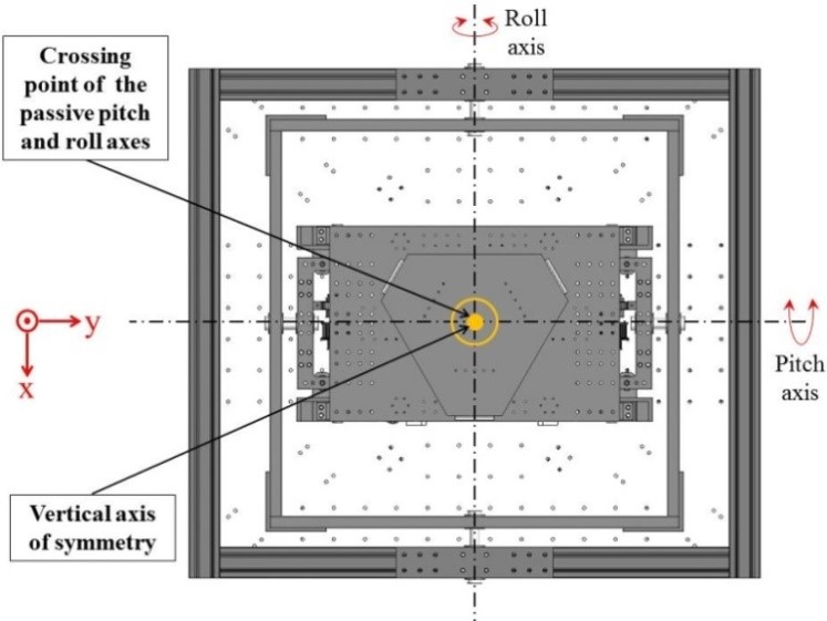 Figure 9. Top view of the stabilizing mechanism on the host vehicle.
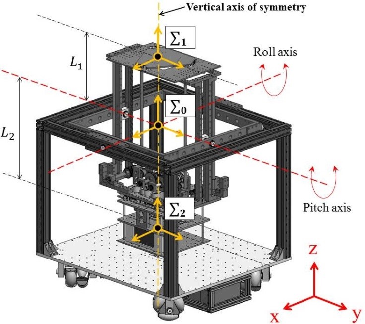 Figure 10. Coordinate frame assignment on the stabilizing mechanism.
A fixed reference coordinate frame is assigned with its origin at the intersection of the passive gimbal’s roll and pitch rotation axes and its vertical axis collinear with the stabilizing mechanism’s vertical axis of symmetry. Positions and rotations of the ISP and the counterweight are defined with respect to this reference frame.
A coordinate frame is assigned to the surface of the inertially stabilized platform with its vertical axis collinear with the mechanism’s vertical axis of symmetry and with its origin at a vertical distance from the origin of the reference frame , above the passive gimbal’s pitch and roll rotation axes.
A coordinate frame is assigned to the counterweight with its vertical axis collinear with the balancing mechanism’s vertical axis of symmetry and with its origin at a vertical distance from the origin of the reference frame , beneath the passive gimbal’s pitch and roll rotation axes.
4.2. Calculation of the Horizontal Coordinates of the Payload Center of Gravity on the Surface of the Inertially Stabilized Platform
In the proposed stabilizing mechanism, the inertially stabilized platform’s effective workspace is a tray resting on top of three CZL204E strain gauge load cells, with which the weight of the payload placed on the tray is measured. The layout of the load cells is shown in Figure 11.
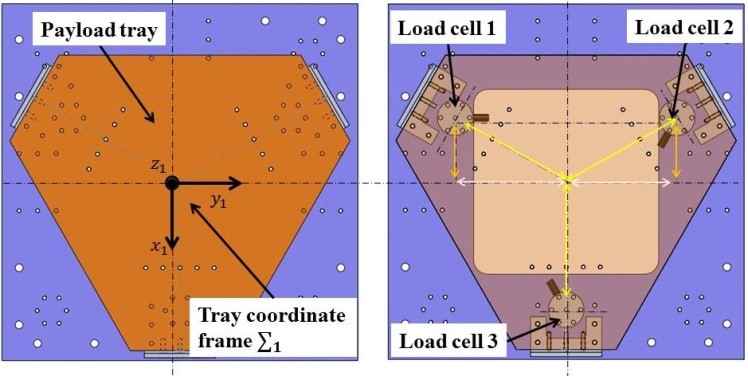 Figure 11. Load cell layout for weight measurement of the payload on the inertially stabilized platform.
The position of the COG of the payload placed on the tray is calculated from the relationship between force measurements of the three CZL204E strain gauge load cells using the multiple-point weighing method. The position coordinates of the payload COG are described with respect to the platform coordinate frame , where is the y coordinate of the position of the payload COG on the platform and is the x coordinate of the position of the payload COG on the platform, as shown in Figure 12.
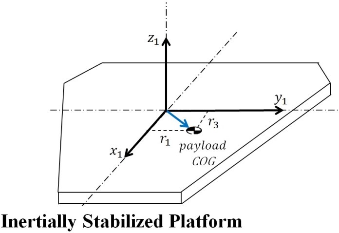 Figure 12. Illustration of the position coordinates and of the payload center of gravity on the surface of the inertially stabilized platform.
Figure 13 illustrates the multiple-point weighing method for calculating the position of the payload center of gravity on the surface of the ISP. The weight of the payload is the sum of the force readings A, B, C of load cell 1, load cell 2, and load cell 3, respectively, described with (4).
The distance corresponding to the y coordinate of the payload COG on the ISP coordinate frame is calculated with (5).
The distance corresponding to the x coordinate of the payload COG on the ISP coordinate frame is calculated with (6).
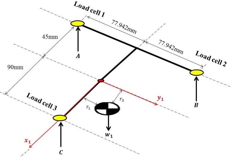 Figure 13. Multiple-point weighing method for calculating the position coordinates of the center of gravity of a payload on the surface of the inertially stabilized platform.
The position coordinates of the payload COG on the surface of the platform are defined with respect to platform coordinate frame with vector (7).
4.3. Calculation of the Vertical Coordinate of the Payload Center of Gravity from the Surface of the Inertially Stabilized Platform
After calculating the horizontal position coordinates of the payload COG on the surface of the platform as described in the previous section, the next step is to calculate the height h of the payload COG with respect to the platform surface, namely its z position coordinate, as seen on Figure 14.
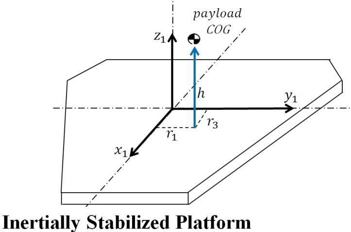 Figure 14. Illustration of the vertical position h of the payload center of gravity from the surface of the inertially stabilized platform.
A payload with weight initially placed on the platform workspace offset from the stabilizing mechanism’s vertical axis of symmetry by distances and will cause the passive gimbal to incline along the roll axis by an angle σ and along the pitch axis by an angle θ, as illustrated in Figure 15. After placing the payload on the surface of the ISP, we describe the positions of all the coordinate frames with respect to the reference frame . We proceed to calculate the height of the payload COG from the surface of the ISP by analyzing the roll and pitch inclination angles of the passive gimbal.
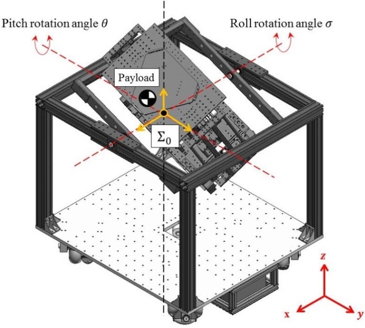 Figure 15. Inclination of the passive gimbal caused by initial placement of a payload on the inertially stabilized platform.
The position coordinates represent the position of the origin of ISP coordinate frame with respect to the fixed reference frame resulting after the pitch and roll rotation of the passive gimbal caused by the placement of the payload on the ISP. These coordinates are described by vector (8).
The position coordinates represent the position of the origin of the counterweight coordinate frame with respect to the fixed reference frame resulting after pitch and roll rotation of the gimbal. These coordinates are described by vector (9).
We now perform a transformation of the position of the payload COG on the surface of the ISP from its description with respect to the ISP local frame (7) to a description with respect to the reference frame The coordinates represent the position of the payload COG with respect to the reference frame resulting after pitch and roll rotation of the passive gimbal. They are described by vector (10).
To perform the calculation of the height h of the payload COG from the surface of the ISP, we carry out a statics analysis of the inclined stabilizing mechanism. For this purpose we derive the spherical coordinates (r, β,α) of the ISP coordinate frame with respect to the reference frame . The spherical coordinates describe the ISP’s radial distance, azimuth angle and elevation angle with respect to the reference frame . The spherical coordinates are used to select a cross-sectional plane in which both the pitch and roll inclination of the ISP are simultaneously accounted for. The inclination of the ISP in roll and pitch is simultaneously described by the elevation angle α of the spherical coordinates of the ISP coordinate frame.
The ISP spherical coordinates r, β,and α are defined by (11), (12), and (13) respectively; they are derived from the ISP Cartesian coordinates described by (8) and are all described with respect to the reference coordinate frame
r = radial distance from the origin of the reference frame to the origin of the ISP coordinate frame .
β = azimuth angle of the point (origin of the ISP coordinate frame ).
α = elevation angle of the point (origin of the ISP coordinate frame ).
We proceed to select a cross sectional plane using the description of the position of the ISP in spherical coordinates derived above. A coordinate frame is assigned to the cross-sectional plane, with its origin coincident with the origin of reference frame , its axis collinear with the projection of radial distance r on the plane, its axis collinear with the axis of the reference frame , and with its axis orthogonal to axes and as illustrated in Figure 16.
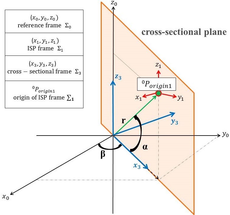 Figure 16. Image of the cross-sectional plane selected from the inertially stabilized platform’s spherical coordinates, and the corresponding coordinate frame assignment .
We now proceed to describe the position of the origin of the ISP coordinate frame , the counterweight coordinate frame , and the position of the payload COG all with respect to the cross-sectional plane frame
The transformation of the position of the origin of the ISP coordinate frame from its description with respect to reference frame (8) to its description with respect to the cross-sectional plane is defined by vector (14).
The transformation of the position of the origin of the counterweight coordinate frame from its description with respect to reference frame (9) to its description with respect to the cross-sectional plane is defined by vector (15)
The transformation of the position of the payload COG from its description with respect to reference frame (10) to its description with respect to the cross-sectional plane is defined by vector (16).
We now proceed to describe on the cross-sectional plane the distance from the ISP’s coordinate frame origin to the position of the payload COG. The position of the ISP coordinate frame described with respect to the cross-sectional plane (14) and the position of the payload COG described with respect to the cross-sectional frame (16) shown in Figure 17. Here α is the elevation angle of the ISP and is the distance from the ISP coordinate frame origin to the position of the payload COG.
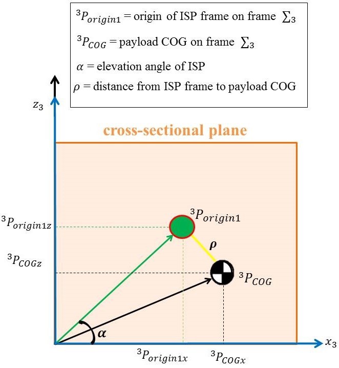 Figure 17. View normal to the cross-sectional plane with the location of the inertially stabilized platform frame and the payload center of gravity.
From the view normal to the cross sectional plane and the coordinate descriptions of the position of the ISP (14) and the payload COG (16) , distance is defined by (17).
Finally, we proceed to take moments under static condition about the crossing point of the gimbal pitch and roll rotation axes (coincident with the origin of the cross-sectional frame ) to calculate the height h of the payload COG as per Figure 18
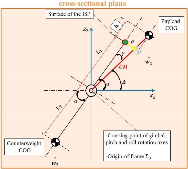 Figure 18. View normal to the cross-sectional plane for the calculation of the height h of the payload center of gravity.
where:
= distance from crossing point of the gimbal rotation axes to the ISP coordinate frame .
= distance from the crossing point of the gimbal rotation axes to the counterweight coordinate frame .
= weight of the payload.
= weight of the counterweight .
OM = distance from the crossing point of the gimbal rotation axes to the payload COG.
α = elevation angle of the ISP.
h = height of the payload COG from the ISP surface.
As illustrated in Figure 18, we use the view of the cross-sectional plane to take moments about the crossing point of the gimbal pitch and roll axes under static condition (20). From this equation the height h of the payload COG from the surface of the ISP is calculated with (21).
5. Control
The pitch and roll inclination angles of the passive gimbal are measured by the onboard SEN-10736 inertial measurement unit. The pitch angle measured is used as feedback in a PID control scheme to actuate the X Stage, displacing the counterweight along the x axis until the passive gimbal reaches a setpoint angle of zero degrees of inclination about the pitch axis [7]. The roll angle measured is used as feedback in a PID control scheme to actuate the Y Stage, displacing the counterweight along the y axis until the passive gimbal reaches a setpoint angle of zero degrees of inclination about the roll axis [7]. As a result, the payload line of sight is oriented to a horizontal position with respect to the inertial reference frame .
Both the X Stage and the Y Stage are each equipped with a Copal RE30E500-213 incremental optical encoder for position feedback. Figure 19 shows the block diagram for the X Stage control and Figure 20 shows the block diagram for the Y Stage control.
For the control of the Z Stage, the control system calculates the target vertical position of the counterweight that satisfies (3) using the weight of the payload measured by the CZL204E strain gauge load cells located on the platform. Once the calculation according to (3) is done, the control system displaces the Z Stage vertically to reach this setpoint. Figure 21 shows the block diagram for the Z Stage control.
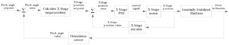 Figure 19. Block diagram for X Stage control.
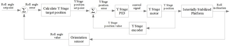 Figure 20. Block diagram for Y Stage control.
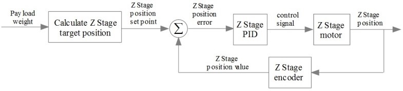 Figure 21. Block diagram for Z Stage control.
6. Experimental setup
The second prototype of the inertially stabilized platform with passive gimbal as well as the host vehicle are here presented. Fundamental experiments were conducted to measure the linear speed of the X Stage, Y Stage, and Z stage. Moreover, a fundamental experiment was conducted to test the accuracy of the calculation of the position of the payload COG on the surface of the inertially stabilized platform.
The stabilizing mechanism mounted on the omnidirectional host vehicle is shown in Figure 22 and its dimensions are shown in Figure 23.
A close-up of the stabilizing mechanism’s counterweight comprised of the XY Stage and the Z Stage is shown in Figure 24.
Figure 25 shows an overview of the motions of the XY Stage and Z Stage of the stabilizing mechanism.
An overhead view of the inertially stabilized platform is shown in Figure 26, and a bottom view of the vehicle’s omnidirectional mobile base is shown in Figure 27.
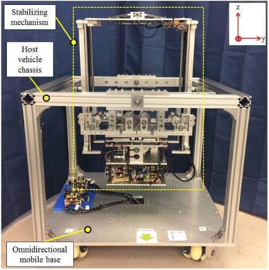 Figure 22. Second prototype of the stabilizing mechanism on the host vehicle.
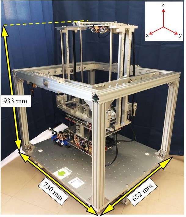 Figure 23. Dimensions of the second prototype.
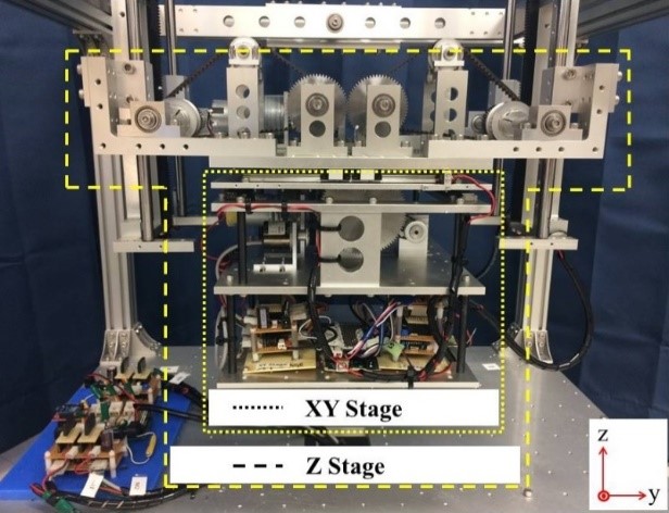 Figure 24. Close-up of the counterweight consisting of the XY Stage and the Z Stage.
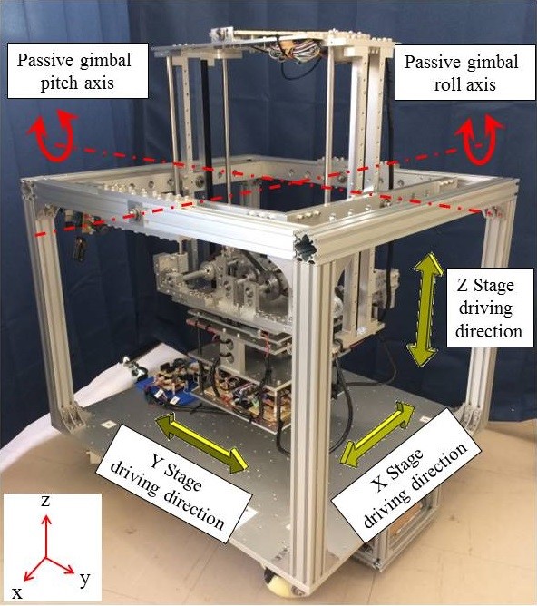 Figure 25. Overview of the motions of the XY Stage and the Z Stage.
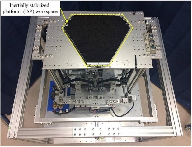 Figure 26. Workspace of the inertially stabilized platform.
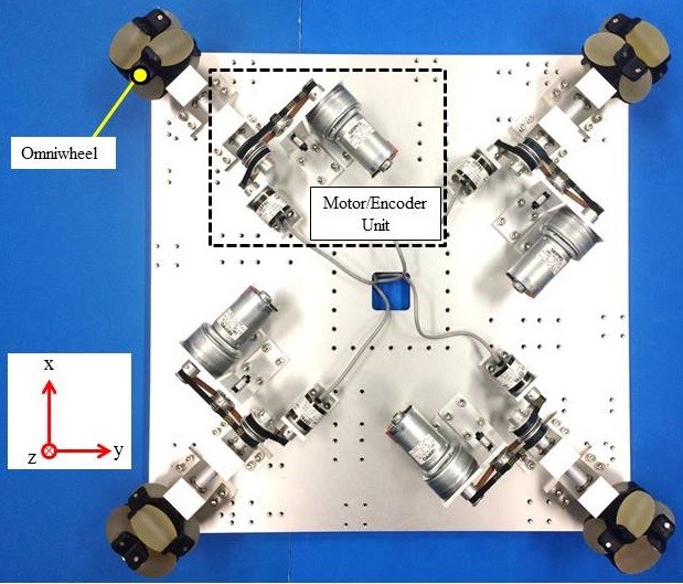 Figure 27. Omnidirectional mobile base of the host vehicle.
The specifications of the inertially stabilized platform are shown in Table 1.
Specifications of the XY Stage and the Z stage are detailed in Table 2 and Table 3, respectively.
Table 1. Specifications of the inertially stabilized platform.
| Inertially Stabilized Platform (ISP) | |
| Workspace area | 69,350 mm |
| Max. payload capacity | 18 kg |
| Max. pitch inclination angle | 40 degrees |
| Max. roll inclination angle | 40 degrees |
| Counterweight | 16.53 kg |
| Inertial measurement unit (IMU) |
SEN-10736 nine degrees of freedom inertial measurement unit Voltage: 3.5 – 16 VDC |
| Weight measurement of payload |
CZL204E strain gauge load cell (3x) Max. capacity: 50 kg Excitation voltage: 9-12 VDC |
Table 2. Specifications of the XY Stage.
| XY Stage | |
| Dimensions | 250mm x 250mm x 124.5mm |
| Material |
Frame: A5052 Planar omnidirectional gear: A7075 X Stage spur gear: SUS304 Y Stage spur gear: SUS304 |
| Motion range on X axis | 81 mm |
| Motion range on Y axis | 115 mm |
| X Stage motor |
Nidec DMN37K50G72B brushed DC Torque: 0.98 Nm Speed: 52.3 rpm Voltage: 24 VDC Gear ratio: 72:1 |
| X Stage encoder |
Copal RE30E500-213 incremental optical encoder Resolution: 500 pulse/rev |
| Y Stage motor |
Nidec DMN37K50G72B brushed DC Torque: 0.98 Nm Speed: 52.3 rpm Voltage: 24 VDC Gear ratio: 72:1 |
| Y Stage encoder |
Copal RE30E500-213 incremental optical encoder
Resolution: 500 pulse/rev |
Table 3. Specifications of the Z Stage.
| Z Stage | |
| Dimensions | 542mm x 453mm x 318mm |
| Material |
Frame: A5052 Rack gear: (2x): S45C Spur gear: S45C |
| Motion range on Z axis | 390mm |
| Z Stage motor |
Nidec DMN37K50G72B brushed DC Torque: 0.98 Nm Speed: 52.3 rpm Voltage: 24 VDC Gear ratio: 72:1 |
| Z Stage encoder |
Copal RE30E500-213 incremental optical encoder
Resolution: 500 pulse/rev |
6.1. Linear Speed of the XY Stage
Fundamental experiments were performed to measure the linear speed of the X Stage as it is displaced along its motion range, and the linear speed of the Y Stage as it is displaced along its motion range. The tests to measure the linear speed of each stage were performed by driving the corresponding stage motor at full capacity from the start of its motion range to the end of its motion range, repeating the motion 5 times for each stage.
Figure 28 shows the velocity profile of the X Stage as it is displaced from rest at 0mm to its maximum motion range of 81mm. The X Stage had an average linear speed of 200.3 mm/s, taking 0.35 seconds to move along its motion range.
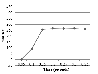 Figure 28. Linear velocity of the X Stage.
Figure 29 shows the velocity profile of the Y Stage as it is displaced from rest at 0mm to its maximum motion range of 115mm. The Y Stage had an average linear speed of 210.2 mm/s, taking 0.5 seconds to move along its motion range.
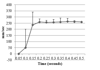 Figure 29. Linear velocity of the Y Stage.
6.2. Linear Speed of the Z Stage
Initially, the deployment of the Z Stage driving motor on the second prototype actuated the Z Stage via a direct attachment of the motor shaft to the driving gear shaft. Experiments revealed that the motor driving the Z Stage lacked enough braking power to maintain the Z stage at a fixed position (setpoint position) on the Z axis. When the Z stage reached its vertical target position and the motor was braked, the downward weight of the XY Stage/Counterweight produced a torque on the motor shaft higher than its braking torque, and as a result, the Z Stage moved down. This caused the control system to drive the Z Stage upward again trying to maintain the target position, resulting in large oscillations of the Z Stage during operation time. Figure 30 shows the previous deployment of the Z Stage motor.
To tackle this problem, we modified the method to drive the Z Stage to a worm gear drive with a reduction ratio of 20:1 This modification improves the lifting torque of the Z Stage to elevate the XY Stage/Counterweight and takes advantage of the non-backdrivability of the worm gear to provide a mechanical break that prevents the Z Stage from moving down once it has reached its vertical target position. Figure 31 shows the modified deployment with worm gear drive to improve lifting torque and provide a mechanical break to prevent a descent of the Z Stage due to gravity.
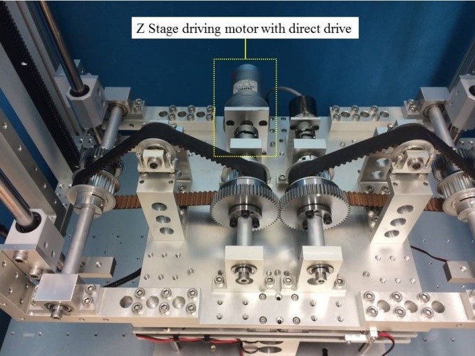 Figure 30. Previous deployment of the Z Stage driving motor.
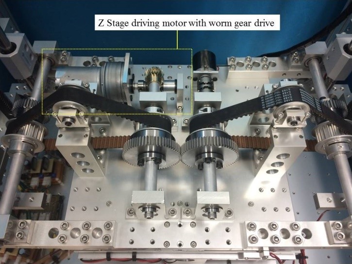 Figure 31. Current deployment of the Z Stage driving motor with worm gear.
With the current deployment of the Z Stage driving motor with worm gear drive, a fundamental experiment was performed to measure the linear speed of the Z Stage as it is displaced along its motion range. The tests to measure the linear speed were performed by driving Z Stage motor at full capacity from the start of its motion range, to the end of its motion range, repeating the motion 5 times.
Figure 32 shows the velocity profile of the Z Stage as it is displaced from rest at 0mm to its maximum motion range of 390mm. The Z Stage had an average linear speed of 5.75 mm/s, taking 67.9 seconds to move along its motion range.
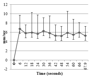 Figure 32. Linear velocity of the Z Stage.
6.3. Calculation of the Position of the Payload Center of Gravity on the Surface of the Inertially Stabilized Platform
For this experiment, a grid with 5mm markers was aligned with the axes of the ISP coordinate frame (Figure 33), and a 1.5 kg calibration weight was placed on eight different positions on the surface of the ISP as payload, corresponding to eight (x,y) coordinates on the ISP coordinate frame . The coordinate position of the payload on the surface of the platform was measured with the multiple-point weighing method discussed in Chapter 4, section 4.2.
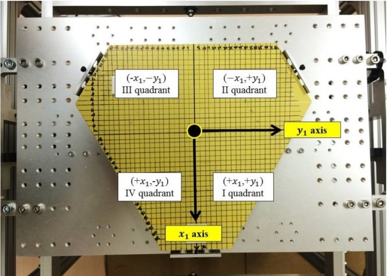 Figure 33. The inertially stabilized platform with a grid for the experiment to calculate the horizontal position of a payload’s center of gravity.
Table 4 shows the results of the measurements of the horizontal position of the payload COG corresponding to its physical position coordinates on the ISP surface. Figure 34 illustrates the results shown in Table 4.
Table 4. Results of the measurements for the positions of the payload center of gravity.
| Location | Physical COG Coordinates in millimeters | Measured COG Coordinates in millimeters | Standard Error in Measured COG Coordinates | |
| (x,y) | (x,y) | x | y | |
| 1 | (-50.0, 0.0) | (-51.16, 0.57) | 0.19 | 0.09 |
| 2 | (-40.0, 60.0) | (-33.97, 63.50) | 8.39 | 0.05 |
| 3 | (-40.0, -60.0) | (-42.09, -59.02) | 0.49 | 0.37 |
| 4 | (0.0, 0.0) | (4.89, 0.44) | 0.06 | 0.09 |
| 5 | (20.0, -50.0) | (24.56, -44.74) | 0.11 | 0.22 |
| 6 | (20.0, 50.0) | (25.76, 51.61) | 0.09 | 0.12 |
| 7 | (70.0, 30.0) | (70.73, 26.29) | 0.15 | 0.08 |
| 8 | (70.0, -30.0) | (73.84, 24.27) | 0.16 | 0.10 |
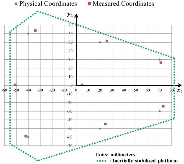 Figure 34. Physical positions of the payload center of gravity on the surface of the ISP and the corresponding measured values.
Future steps
The next step in this research is to experimentally test the proposed theoretical framework for the calculation of the height of the payload center of gravity presented in Chapter 4, section 4.3.
Applications
The stabilizing strategy and motion isolation method with passive gimbal axes discussed in this paper rely on adjusting the mass properties of the system. Since the calculations and motor actuations to accomplish payload stabilization are performed at startup, once the system is balanced no motor output or computational calculations are required during the rest of operation time of the system. These feature reduces the power requirements and the computational resources needed during the operation time of the stabilizing system, making it suitable for battery powered-applications and applications where computational capability is restricted.
Furthermore, the ability of the proposed stabilizing mechanism of having a payload placed in an arbitrary position on the platform and stabilizing its LOS makes its use intuitive and simple, suitable for applications involving human interaction without requiring skill or assembly.
Conclusion
In this paper, a method for disturbance isolation of an inertially stabilized platform using a passive gimbal was described. In the method discussed, the inertially stabilized platform is attached to a gimbal suspended on the host vehicle chassis by freely rotating (passive) joints, with no torque coupling between the gimbal and the host vehicle chassis. As a result, the gimbal is isolated from the vehicle chassis angular motion.
A consequence of the use of a passive gimbal is that in order to stabilize the line of sight of a payload, the payload’s weight and the position of its center of gravity are required to be known. A method of calculating the three-dimensional position of the center of gravity of a payload once it is placed on the inertially stabilized platform was presented. The calculation of the (x,y) coordinates of the payload COG was tested experimentally and demonstrated to be adequate.
Conflict of Interest
The authors declare no conflict of interest.
Acknowledgement
This research was supported by Equos Research Co., Ltd.
- Erick Moya, Kenichi Shimakawa, Akira Satou, Adrian Zambrano, Kenjiro Tadakuma, Riichiro Tadakuma, “Study on the Inertial Stabilization of a Payload by Center of Gravity Displacement”, Proceedings of 2016 IEEE/SICE International Symposium on System Integration (SII), pp.266-271.
- Daniel R. Otlowski, Kurt Weiner, Brandon A. Rathburn, “Mass properties factors in achieving stable imagery from a gimbal mounted camera”, Proceedings SPIE, Airborne Intelligence, Surveillance, Reconnaissance (ISR) Systems And Applications Wadsworth, vol. 69460B, 2008.
- J.M. Hilkert, “Inertially Stabilized Platform Technology Concepts and Principles”, IEEE Control Systems, vol. 28, 2008, pp. 26-46.
- Kenjiro Tadakuma, Riichiro Tadakuma, Kyohei Ioka, Takeshi Kudo, Minoru Takagi, Yuichi Tsumaki, Mitsuru Higashimori, Makoto Kaneko, “Omnidirectional Driving Gears and their Input Mechanism with Passive Rollers”, Proceedings of 2012 IEEE/RSJ International Conference on Intelligent Robots, pp.2881-2888, 2012.
- P. J. Kennedy, R. L. Kennedy, “Direct Versus Indirect Line of Sight (LOS) Stabilization”, IEEE Transactions on Control Systems Technology, vol. 11, 2003, pp.3-15.
- Myer Kutz, Handbook of Measurement in Science and Engineering, vol. 1, Wiley, 2013, pp.277-279.
- Michael Masten, “Inertially Stabilized Platforms for Optical Imaging Systems”, IEEE Control Systems, vol.28, 2008.