A Secure Communication Framework for ECUs
A Secure Communication Framework for ECUs
Volume 2, Issue 3, Page No 1307-1313, 2017
Author’s Name: Ali Shuja Siddiqui1, a), Yutian Gui1, Jim Plusquellic2, Fareena Saqib1
View Affiliations
1Dept. of Electrical and Computer Engineering, University of North Carolina at Charlotte, U.S.A.
2Dept. of Electrical and Computer Engineering, University of New Mexico, U.S.A.
a)Author to whom correspondence should be addressed. E-mail: alishuja@gmail.com
Adv. Sci. Technol. Eng. Syst. J. 2(3), 1307-1313 (2017); ![]() DOI: 10.25046/aj0203165
DOI: 10.25046/aj0203165
Keywords: Automotive Security, Controller Area Network, Physical Unclonable Functions

Export Citations
Electronic Control Units (ECUs) generate diagnostic and telemetric data that is communicated over the internal vehicular network. ECUs are resource constraint devices and have limited resources to devote for data security. In recent times, threats against vehicular networks have emerged that require attention of the research community. In this paper, we demonstrate data security threats in automobile, and present a hardware based security framework that provides real time secure communication using lightweight cryptographic primitives and propose hardware based authentication protocol. Implementation details, performance and security analysis of proposed framework are presented.
Received: 24 April 2017, Accepted: 24 June 2017, Published Online: 01 August 2017
1. Introduction
Vehicles are no longer composed of just mechanical components with limited control operations of electrical components. Digital transformations in electronics have contributed in the advancement of automotive industry in terms of customer interactions and experience in improving the overall driving experience of a vehicle and critical operations. Some examples of on-board electronic components are air-fuel mixing, temperature-control, thermostats, vents, doors-locking, seat-adjustments, radio, wind-shield wipers, transmission, ignition, engine, steering, brakes, acceleration, air-bags, navigation, in-dash entertainment, cameras, braking system, etc. Electronic systems that are connected with on-board systems are called Electronic Control Units (ECU). ECUs work in cooperation with each other, and need to communicate their state with one another. Instead of using dedicated signal wires for information exchange, that may require a lot of wiring and effort on part of the car manufacturer, the automotive industry has moved towards using data communication networks. Similar to traditional data communication networks, data security of the ECU network is becoming a concern. Following section covers the vulnerabilities, and recent attacks on on-board car networks and the new security requirements. The security vulnerabilities are demonstrated and existing countermeasures and their limitations are discussed. This is an extension to the paper [1] which was presented in IEEE Vehicular Networking Conference 2016. Columbus, OH, U.S.A.
1.1. Recent Documented Attacks
In 2014, a group of researchers were able to remotely control a Jeep Cherokee[2]. The vehicle is equipped with an on-board infotainment system. To gather local information, it uses an internet connection to connect to its server. The researchers could remotely hack into the dashboard system, using software vulnerability. The dashboard system is also connected to the internal network of connected ECUs using a popular network standard known as Controller Area Network (CAN)[3]. This gives access to all the other actuation units such as the brakes, accelerator, steering control etc. A more recent attack is discussed in [4]. The authors extracted master global shared encryption keys from deciphering the software code using a wireless key fob. This gave the researchers access to shared keys used by all the vehicles using the wireless key fob system from the affected brand.
1.2. Current Security Needs
A robust and secure framework is needed to improve the resiliency to malicious attacks. Traditional cryptographic primitives are computation intensive and rely on secrecy of shared
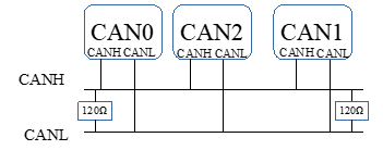 Figure 3 Block diagram of the Experimental Setup. Figure 3 Block diagram of the Experimental Setup. |
or session keys, and are applicable on large systems like servers and secure databases. These are unsuitable for embedded devices with fewer resources to allocate dedicated hardware for implementing security protocols with extra storage requirements. Alternatively, if external Hardware Security Modules (HSM) are considered to provide security, they are costly and require additional physical area and power.
This paper demonstrates a hardware based light authentication framework integrating strong physical unclonable function for secret key generation and light cryptographic primitives, such as Elliptic Curve Cryptography to improve authentication protocol for small and resource constrained embedded devices at lower levels of composition. We evaluate the security methods for CAN protocol and propose techniques to mitigate those attacks on ECUs. Furthermore, the framework addresses the issue of unauthorized physical access to a vehicle via electronic means, and to the connected digital components within a vehicle.
2. The CAN Bus Protocol
The CAN bus, known as ISO 11898 architecture is a multi-master bus connecting embedded components, I/O interfaces as well as gateways to communicate with the external world. It consists of three signals, CAN High, CAN Low and Ground, and the CAN standard specifies three data rates 125kbps, 500 kbps and 1Mbps. In the more recent standard for CAN Bus, named CAN Flexible Datarate, CAN allows transfers of additional frames at non-standard and faster speeds.
Figure 1 describes the standard data frame of CAN bus. The SOF bit denotes the start of frame, 11 bits store destination ID, Data field of 64 bits and CRC field is 15 bits to hold the checksum of the entire packet. The length of the standard CAN frame is 108 bits whereas 131 for an extended CAN frame. On the physical medium CAN uses Non-Return to Zero (NRZ) encoding, that is after five consecutive zeroes on the stream, an extra ‘1’ bit will be added to that position before putting it on the bus.
3. Threat Models
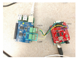 Figure 2 Experimental Setup. Figure 2 Experimental Setup. |
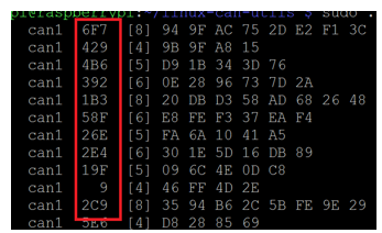 Figure 4 Screenshot of data transfer on the CAN. Figure 4 Screenshot of data transfer on the CAN. |
CAN is susceptible to replay, man in the middle and stealing identifiers attacks. We demonstrate these attacks on CANBus, with the testbed using Raspberry Pi 2, PiCAN Duo CANBus Shield, Arduino UNO and CAN-BUS Shield.
The PiCAN shield with two CAN nodes is connected with the Raspberry Pi. These nodes are considered to be legitimate nodes on the network. These nodes are referred as CAN0 and CAN1, as shown in Figure 2. The malicious node CAN2 is a CAN shield which is connected to an Arduino UNO. Figure 3 describes the block diagram of the complete setup.
3.1. Eavesdropping
CANBus is an insecure communication medium that transmits data in broadcasting the unencrypted packets to all connected nodes on the network. Malicious node getting physical or remote access to CANBus network has access to all the packet transfers and payload. Figure 4 shows traffic of packets on CANBus. The messages and destination identifiers are broadcasted and sent unencrypted on CAN. CAN0 messages for other nodes can be seen and recorded by CAN1. Similarly, any other device physically connected to the CAN bus can read all the communication over the network.
To mitigate eavesdropping, the information passing on the bus needs to be securely encrypted. In [5], the authors present an external security solution, and [6] proposes 3DES encryption and an external controller for the transfers and traffic monitoring. The added area, power requirements and slower performance of the software based encryption and decryption processes make the solution impractical.
3.2. Stealing Identifiers
As shown in the Figure 4, the destination address in the identifier field are visible to the hacker/ attacker on the CAN bus. All devices probe the ID field of each message received and based on the ID, deduce if the message was meant for them or not. Malicious device records these identifiers and can launch attacks against other nodes.
In [7], an authentication and encryption mechanism is described, but it requires about three times more CPU cycles than the cycles required for normal operation of a CAN node.
3.3. Non Repudiation
The frame consists of the destination identifier and not source identifier. The communication network cannot confine the attack or identify the originating node based on the network analysis. This results in incorporating non-repudiation requirements at each device (ECU).
3.4.
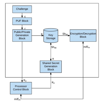 Figure 8 Secure block implemented at each client node. Figure 8 Secure block implemented at each client node. |
Denial of Service
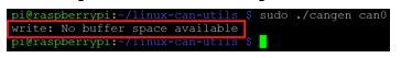 Figure 6 Screenshot demonstrating buffer-overflow occurring at CAN0. Figure 6 Screenshot demonstrating buffer-overflow occurring at CAN0. |
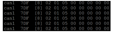 Figure 5 Screenshot of CAN2 flooding the network. Figure 5 Screenshot of CAN2 flooding the network. |
Denial of Service attacks makes the resources or services unreachable; the CAN communication channel is made inaccessible by the malicious node CAN2 by broadcasting random messages on the bus without pause as demonstrated in figure 5, while CAN0 and CAN1 are exchanging information. With the vendor provided code, the legitimate nodes stopped operation and notified about receiving a buffer overflow error as shown in Figure 6.
In section 4 we propose a hardware based framework to introduce secure communication over CANBus and provide countermeasure against the discussed attacks.
4. Hardware Based Encryption and Digital Signature Solution
The limited processing power available on the hardware and real time constraints bound the traditional software based cryptographic solutions to provide secure communication. In embedded systems with a software solution, an attacker can extract the executable source code of the device using various methods to reverse engineer cryptographic algorithms and keys[8][9][4].
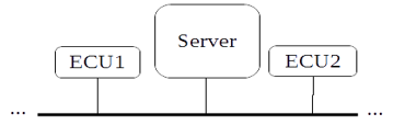 Figure 7 Server locally connected to the nodes. Figure 7 Server locally connected to the nodes. |
We propose hardware based secure enhancements to each connected electronic control unit (ECU). The secure framework can be embedded into the processor fabric itself as a co-processor. The hardware design is made to minimize software dependency on the resource scarce devices. Additionally, with incorporation of hardware based obfuscation techniques, reverse engineering attacks or attempts for extraction of keys using hardware based attacks can be further mitigated. The proposed framework requires no secret keys to be stored on non-volatile memory within the nodes/ECUs, thus eliminating the probing attacks.
The security framework is based on client server architecture. A local server node present on the network is responsible for handling all ECU nodes that are joined on the network. Each client must first be registered and authenticated at the server before they can communicate with the other nodes on a network. This process takes place in a secure and trusted environment, referred to as registration. Registration can be performed during manufacturing, assembly of vehicle components or at the trusted diagnostic centers. Figure 7 illustrates the local on-board server.
Figure 8 shows the enhancements and design flow in form of block diagram of each secured ECU. Our framework assumes the server is secure and trusted. Following subsections discuss each of the components and their function in the framework.
4.1. PUF Block
Physical unclonable function (PUF) is an emerging physical layer cryptographic primitive used in hardware security and privacy protocols. These are embedded structures that utilize inherent manufacturing process variations to extract unique but reproducible secrets [10][11]. PUFs are based on a challenge-response pair (CRP) mechanism. The challenge for a PUF is defined as a digital input, usually in the form of a bitstring of ‘0’s and ‘1’s. The output of a PUF is also digital but for most PUFs, this requires an on-chip mechanism to convert the small analog variations leveraged by the PUF to be digitized.
There two different types of PUFs, namely Weak and Strong PUFs. A major difference between the two is that the weak PUFs have few challenges for which they can uniquely generate a key whereas strong PUFs have a large challenge space and therefore have a unique response for most of the challenges. The bit-generation for cryptographic applications is a two-step process that is enrollment and registration. During the enrollment process, each PUF is given a set of challenges and the response pairs are recorded. Later when the PUF is in field, these responses are regenerated for use in identification and encryption applications.
During the registration, each ECU produces a unique reproducible response/key that serves as private key. This response is reproduced using the error correction code and is used to generate public private pair. Helper data for reproducing the secrets is stored on the NVM of ECU for the given challenge and public key is communicated to the secure server, where it is stored. PUF based authentication is implemented within vehicle network[11]. All client nodes (or devices) are enrolled at the server before they can be used. The registration process is summarized in Table I.
Table I. Registration of nodes in a trusted environment.
|
Algorithm: Registration process of client nodes in a trusted environment. Input: Challenge c, configuration parameters for the ECC curve. Output: Public key Ka of ECU. 1: At each client node, input a challenge c for the PUF Block. |
4.2. Private/Public Key Generation Block
We implement Elliptic Curve Cryptography Diffie-Hellman (ECDH) based asymmetric key exchange and encryption engine in hardware. ECC algorithm is suitable for the resource constraint devices, providing same strength of security as RSA. ECC algorithms are implemented in Galois Field(GF) which limit the range of output values and thus reducing the resource requirements. ECC implementations have been presented over two types of Galois Fields, namely Prime Fields (GF(Fp)) and Binary Fields (GF(F2^m)). National Institute of Standards and Technology (NIST) provides a set of recommended elliptic curves (http://csrc.nist.gov/groups/ST/toolkit/documents/dss/NISTReCur.pdf).
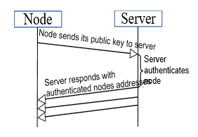 Figure 9 Sequence Diagram for Authentication. Figure 9 Sequence Diagram for Authentication. |
This block is used to generate public and private keys for a node. It is used in the one-time registration process (as described in the previous subsection). Based on the reliable PUF response, public and private keys are generated at each ECU during the authentication process that is initiated every time the vehicle starts (turning on of the ignition).
4.3. Authentication and Shared Key Generation Process
During the startup, each connected device requires authentication with the server to enable trusted environment. ECU sends a packet with its own id as target identifier and its public key encrypted with the shared key formed using ECC in the payload. The shared key block is used to generate a shared key between two communicating nodes to have an encrypted communication. At the startup of vehicle each device/ECU, the private key of the current node and the public key of the server, are used in Elliptic curve Diffie-Hellman (ECDH) algorithm for the secret shared key generation. This shared key is used in symmetric key encryption algorithm. All generated keys are stored in the volatile memory for the whole time vehicle is running and requires real time communication.
Server decrypts the payload and compares the public key with the sender ID sent in the arbitration bits. Once the ECU is authenticated, server shares the public keys of the other ECUs the requesting node is allowed to communicate.
Table II. Algorithm for authentication performed at the beginning of each session.
|
Algorithm: Authentication process. Input: None. Output: None. 1: Each ECU generates PUF response r using stored challenge c, and helper data. 11: Each node communicates with the other nodes and generates session keys using both its private key and other nodes public key. |
The authentication process is a timed process. If any node fails to authenticate itself with the server in the time allocated, then it is blacklisted for communication for the entirety of that session. Private keys for all nodes are generated at run time and are not stored to ensure security. No private keys leave the node and are erased at the end of session. Figure 9 illustrates the sequence of communication during authentication of a node.
4.4. Key Storage
The key storage block consists of a non-volatile memory (NVM) to store:
- Input challenges to capture unique responses from PUF on each ECU.
- Helper data consists of tuning stages configuration to re-produce PUF response for private key(discussed in the next section).
- Public key Ks of the server for server authentication.
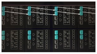 Figure 11 Section of a PUF delay line. Figure 11 Section of a PUF delay line. |
- Parameters to generate public private key pairs.
The framework allows each ECU to generate the private key on fly thus does not require it to be stored in a NVM. Private keys can be stored temporarily in volatile storage along with the shared session keys between ECUs. For each pair of communicating nodes, the following elements are stored in the volatile key storage:
- Shab: Generated Shared secret key for encryption for each pair of nodes (a being the source node and b the node being destination node).
- Kb: Public key of the communicating node.
No access is possible to the storage other than to the nodes connected to it.
4.5. Encryption / Decryption Block
Once shared keys are generated for each pair of nodes, these keys can be used for encryption and decryption for the given session. Every message that is sent must first be encrypted before it can be transmitted. Selection of a symmetric key algorithm is dependent on the choice of the system designer, for example an AES-128 engine. The message is sent to the Encryption / Decryption Block that encrypts the message at the sender and decrypts the message at the receiving node using the shared key.
5. Implementation and Performance Analysis
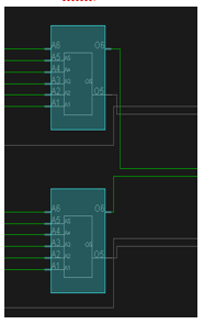 Figure 10 Implementaion of a single PUF stage. Figure 10 Implementaion of a single PUF stage. |
Following section discusses the implementation details of framework and its performance evaluation. Xilinx Kintex KC705 FPGA Evaluation Board is used to implement the design IP with the clock speed of 200 MHz.
5.1. PUF Implementation
The Arbiter PUF is a strong PUF with multiple CRPs that utilizes the process variations in the identical delay lines to generate response bits. The traditional Arbiter PUF implementation is hard to implement on FPGAs because of limited capability on place and route process. This causes systematic bias and the bitstream is not random. An alternative Arbiter PUF implementation is proposed in [12] that utilizes the internal delays of an LUT as a source of entropy for the process variation. The FPGA implementation design details with symmetric delay lines are in further explained in [12].
A single stage of the delay line is illustrated in figure 10. The output is a function of A1, where A2 to A6 inputs decides the route of input to output. LUT is configured as an invertor, when the input signal A1 is 0, the output changes to 1 and vice versa. A rising edge is propagated to the first LUT of both upper and lower path that propagated through 64 stages. In our implementation, we have instantiated 16 copies of lower and upper delay lines to produce 16-bit output response for each given challenge. The routing between the stages is shown in Figure 11.
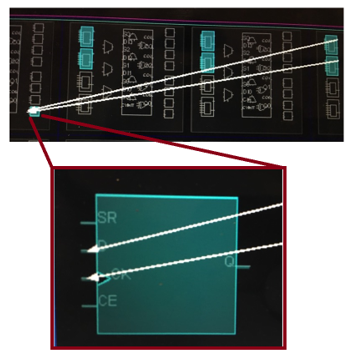 Figure 12 PUF Response stored in DFF.
In order to fine tune the delay difference due to routing, tuning stages are added to the end of the delay lines as described in [12]. Each delay line ends at an arbiter, in our implementation, we are using a D Flip Flop. The difference in the delay caused by the physical variation will result in either capture of a ‘0’ or a ‘1’ based on whether the lower or upper rising edge is reached on the flip-flop clk or D input respectively. The capture stage is illustrated in figure 12. The implementation uses a total of 2416 LUT slices.
5.2. Key Generation Subsystem
ECC engine operating over the binary field GF (2^163)is used [13]. The ECC engine is only used on boot up to generate the public and the shared keys. Figure 13 shows the internal configuration of the ECC core.
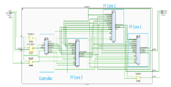 Figure 13 Block Diagram of the ECC Core. Figure 13 Block Diagram of the ECC Core. |
The selected implementation of the ECC engine is organized as a pseudo multi-core processor and has a total of three cores for finite field (FF) computation. They are connected using a RISC like instruction controller. For computation of a single point multiplication, the ECC core requires a total of 1428 cycles. Since our target platform is running on 200 MHz, the total time to compute a single multiplication point is 7.14 microseconds. In the process for shared key generation, there is a need for two single point multiplication operations at each node. On our target platform, the ECC core uses a total of 25,454 LUT slices.
5.3. Encryption/ Decryption
The encryption/decryption module consists of AES-128 for encryption. The AES engine uses the shared key generated by the ECC subsystem to encrypt any traffic leaving the node and decrypt any traffic coming in. AES-128 engine takes a total of 22 clock cycles for encryption and decryption and a total of 110 nanoseconds. The AES engine has a footprint of 2560 LUT slices.
Table III shows a comparison of different block computation speeds at different clock speeds.
Table III. Comparative analysis of block computation speeds at different system clock rates.
| AES-128 | FF Multiplication | |
| At 60 MHz | 366.66 ns | 23.8 µs |
| At 100 MHz | 220 ns | 14.28 µs |
| At 200 MHz | 110 ns | 7.14 µs |
5.4. Storage Elements
For implementing the storage elements of the framework, we are using the FPGA’s on-fabric block RAM resources. A block RAM of 128-bit width and 512 elements is instantiated. On our target board, a total of two 36K BRAM elements were used. This memory element has a read and write speed of one cycle.
5.5. Timing Analysis
The framework has system clock speed of 200MHz and CAN speed is 1Mbps. Time for transmitting one bit at the data rate of 1Mbps is 1µs. We are ignoring bit stuffing due to NRZ encoding in our computation. The time required to transmit one data frame is 1 x 10⁸µ = 108 µsecs. Each frame has a total of 64 data bits, to send an AES-128 encrypted 128-bit message, two data frames are required. The total time for transmission for an encrypted message is 108µ x 2 = 216 µsecs.
During Authentication
At the time of boot up, at each node the first the public key is generated using the private key. This process requires one point multiplication operation to be performed in the ECC core. As stated in subsection 5.2, this operation requires a total of 7.14µsecs. Using the stored public key of the server, another point multiplication operation will be required to generate the shared encryption key. Per Table II, this key is encrypted before it is sent to the server. The encryption operation takes 110 ns. Therefore, the total minimum time required from boot-up to sending the server the shared key is:
(7.14µ x 2) + 110ns +(2 x 10⁸µ) = 230.39µs.
For each node that has been authenticated by the server, the server will send a 3-part message (as described in figure 12) to all the connected nodes. The first part contains the node ID of the node authenticated, and the two parts (total of 128 bits) will consist of the encrypted public key of an authenticated node.
Time taken to send these three messages is:
108µ x 3 = 324 µs.
This process will be repeated for all successfully authenticated nodes.
Since the public key of an authorized node is encrypted in the message, it needs to be decrypted. This process will take another 110 nanoseconds. To generate the shared key for that public key requires another 7.14 µs by the ECC unit.
During normal operation
During normal operation, CAN message is encrypted, it will take a total of two frames to transmit a message. Table IV gives a message overhead incurred for authentication on CANBus communication operation.
Table IV. Overhead overview at standard can connection speeds.
| 125 kbps | 500 kbps | 1 Mbps | |
| Time for sending one frame | 864µs | 216µs | 108µs |
| During Authentication | |||
| Node sending encrypted message to server (2 frames) | 1.728ms | 432µs | 216µs |
| Server’s reply (3 frames) | 2.592ms | 648µs | 324µs |
| Normal Operation | |||
| For a message (2 frames) | 1.728ms | 432µs | 216µs |
6. Security Analysis
The proposed framework assumes a secure server, and the legitimate/authorized ECUs are not compromised and does not allow unauthorized code execution. In the proposed framework, the payload of CAN Bus packets are encrypted. There are no private key storage or exchanges in the untrusted field. An ECU node stores only the public key of the server. This makes it difficult for an attacker to retrieve keys through probing or man in the middle attack.
No new device can be added in the field, since the device needs to register with the server in a trusted environment before the server can send the shared key of this node to the other connected ECUs, it must be authenticated. Since the malicious node’s public key is not stored in the server, it will not authenticate it and therefore will not communicate its ID with the other nodes. Thus, eliminating backdoors for accessing the network physically. All the nodes have different keys and as such on compromise of a single node, even if an attacker can retrieve a private key from one node, the private key to the other node will still be unknown to the attacker.
In the scenario where an attacker has acquired the public key of a legitimate node on the network or in case of a server database compromise, an adversary can only retrieve the public keys of participating ECUs. Once a communication from the adversary is initiated, the legitimate node will reject it since public key was not initially sent by the server.
7. Conclusion
In this paper, we investigate the threat models of internal vehicular network communication using CANBus. We present a secure framework for authentication and point to point encrypted communication for ECUs. Paper presents the architecture and implementation details and area overhead of FPGA implementation. The hardware based security solution for the resource constraints and time critical applications are viable for the automotive industry.
Acknowledgement
This work is supported by National Science Foundation under grant no. 1566530 and 1623299.
- A. S. Siddiqui, Y. Gui, J. Plusquellic, and F. Saqib, “Poster: Hardware based security enhanced framework for automotives,” in 2016 IEEE Vehicular Networking Conference (VNC), 2016, pp. 1–2.
- C. Miller and C. Valasek, “Remote Exploitation of an Unaltered Passenger Vehicle,” Black Hat USA, 2015.
- BOSCH, “BOSCH CAN Specification,” 1991.
- F. Garcia, D. Oswald, and T. Kasper, “Lock It and Still Lose It–On the (In) Security of Automotive Remote Keyless Entry Systems,” in USENIX Security 2016, 2016.
- A. Hanacek and M. Sysel, “Design and Implementation of an Integrated System with Secure Encrypted Data Transmission,” Springer International Publishing, 2016, pp. 217–224.
- G. Singh, “A study of encryption algorithms (RSA, DES, 3DES and AES) for information security,” Int. J. Comput. Appl., 2013.
- Q. Wang and S. Sawhney, “VeCure: A practical security framework to protect the CAN bus of vehicles,” in 2014 International Conference on the Internet of Things (IOT), 2014, pp. 13–18.
- S. Ravi, P. Kocher, R. Lee, G. McGraw, and A. Raghunathan, “Security as a new dimension in embedded system design,” in Proceedings of the 41st annual conference on Design automation – DAC ’04, 2004, p. 753.
- D. Papp, Z. Ma, and L. Buttyan, “Embedded systems security: Threats, vulnerabilities, and attack taxonomy,” in 2015 13th Annual Conference on Privacy, Security and Trust (PST), 2015, pp. 145–152.
- C. Herder, M.-D. Yu, F. Koushanfar, and S. Devadas, “Physical Unclonable Functions and Applications: A Tutorial,” Proc. IEEE, vol. 102, no. 8, pp. 1126–1141, Aug. 2014.
- W. Che, F. Saqib, and J. Plusquellic, “PUF-based authentication,” in 2015 IEEE/ACM International Conference on Computer-Aided Design (ICCAD), 2015, pp. 337–344.
- M. Majzoobi, F. Koushanfar, and S. Devadas, “FPGA PUF using programmable delay lines,” in 2010 IEEE International Workshop on Information Forensics and Security, WIFS 2010, 2010.
- Y. Zhang, D. Chen, Y. Choi, L. Chen, and S.-B. Ko, “A high performance pseudo-multi-core ECC processor over GF(2 ^ 163),” in Proceedings of 2010 IEEE International Symposium on Circuits and Systems, 2010, pp. 701–704.