Incremental Control Techniques for Layout Modification of Integrated Circuits
Incremental Control Techniques for Layout Modification of Integrated Circuits
Volume 2, Issue 3, Page No 1196-1201, 2017
Author’s Name: Patrik Vacula1, 2, a), Vlastimil Kotě1, 2, Adam Kubačák1, Milan Lžíčař1, Radek Zelený1, Miroslav Husák2, Jiří Jakovenko2
View Affiliations
1STMicroelectronics, IBC Building, Pobřežní 620/3, Prague 8,186 00, Czech Republic
2Department of Microelectronics, Faculty of Electrical Engineering, Czech Technical University in Prague, Technická 2, Prague 6, 166 27, Czech Republic
a)Author to whom correspondence should be addressed. E-mail: patrik.vacula@st.com
Adv. Sci. Technol. Eng. Syst. J. 2(3), 1196-1201 (2017); ![]() DOI: 10.25046/aj0203151
DOI: 10.25046/aj0203151
Keywords: Layout, Mouse and Keyboard Control, Gesture Control

Export Citations
Analog layout is created in integrated circuits (IC) computer aided design (CAD) environment and during realization requires a lot of modifications of database objects. Because database objects modification is time consuming, then any improvement and simplification of modification flow in IC CAD environment can increase layout productivity. A proposed new modification concept can speed-up layout work and is very intuitive and easily put into practice. In advance, it allows to apply modern gesture tracking devices for control. By simplifying control of layout object modifications, the productivity of analog layout creation has been improved in the range of 23% to 66%.
Received: 28 April 2017, Accepted: 11 June 2017, Published Online: 20 July 2017
1. Introduction
Virtuoso Layout Suite is very universal and user friendly environment for physical implementation of integrated circuits (IC) [2]. This IC computer aided design (CAD) environment supports the Cadence SKILL programming language, which allows implementation of new features [3]. In process of an analog layout creation, engineers spend a lot of time by modifying layout objects properties, inserting accurate values into forms, and confirmation of different windows. Common concept for modification of selected layout objects is through the Edit Properties window as it is depicted in Figure 1.
A width of selected wire can be changed by using a bindkey to call the Edit Properties window, then type a new value for the wire width and press the OK button to apply. This default concept is working well but consist of four steps. If layout object modifications are done very often, then an improvement of the default control concept should speed up the analog layout creation. Considerable effort has been devoted to the creation of a user-friendly and effective interface [4] where principles of IC CAD environment have been described. Since then, evolution of graphic user interface has led to more complex control of CAD systems. This paper introduces a new effective way of IC CAD environment control reducing pop-up windows and forms
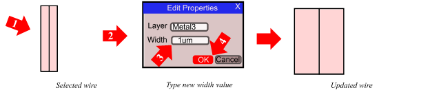 Figure 1 The example of standard four steps modification flow for wire width change in the Virtuoso Layout Suite
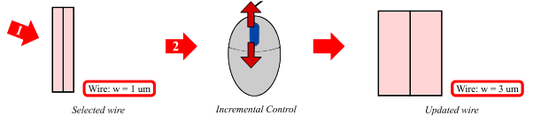 Figure 2 Two steps for the wire width modification [1]
 Figure 3 Height modification of pins with labels
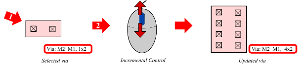 Figure 4 Via modification of rows, columns or both
2. New Incremental Control Concept
A new control concept for changing of layout object properties is defined. The main principles are as follows:
- Replacement of numeric value typing by incremental approach.
- Suppression of the pop-up Edit Properties windows for the most frequent operations.
- Display of changed values in a status bar.
- Application of the same control bindkeys on different layout objects.
- Application of different bindkey modifiers on different layout object properties.
- Possibility of using classic and modern control methods for incremental operations.
This new control concept is called the Incremental Control, where an increment value is applied directly instead of typing a numeric value [1]. After application on a selected wire, the width modification flow is simplified to scrolling of a mouse wheel, which is shown in Figure 2. The exact width value is displayed in the status bar, which allows a user to have all the modifications under control [1].
The same concept of the Incremental Control is also applied on modifications of other layout objects such as pins and their labels (Figure 3). To enlarge or shrink selected pins and their labels, scrolling of the mouse wheel is just needed. In the status bar, the user is informed about pin dimensions or the actual labels height.
The Incremental Control on additional layout objects like vias can be applied (Figure 4). Because the mostly changed properties of via object are rows and columns, control of two independent parameters is needed. To do so, a different bindkey modifier is used to differentiate between rows and columns increment. For example bindkey “Ctrl + mouse wheel” is used to change via columns while bindkey “Shift + mouse wheel” is used to change via rows.
In the status bar, the user is informed about via array dimensions to immediately know the exact count of rows and columns. Information in the status bar is for the Incremental Control very important because it contains accurate actual values.
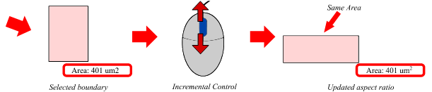 Figure 5 Aspect ratio modification of rectangular objects
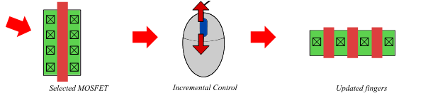 Figure 6 NGF modification of MOSFET
Another practical case for use of the Incremental Control is ability to reshape rectangular layout objects while keeping fixed area. This helps especially during floorplan tasks when the user is able to very quickly modify the aspect ratio of boundaries or rectangles circumscribed to sub-cells to fit expected area. The Incremental Control approach with mouse scrolling is very effective way how to do so (Figure 5).
The Incremental Control allows layout engineers to get simple access to a reshape utility which keeps a rectangular object area and thus has positive influence on productivity of floorplaning as layout engineers can quickly browse among all variants of a rectangle shape to find an optimum. Each modification of the rectangle aspect ratio with the Incremental Control is from user point of view ergonomic and intuitive. In the status bar, the user is informed about an area of the selected rectangle. Such information is very important for floorplaning and is available after each transformation with the Incremental Control.
Now main analog layout objects are discussed. The most important ones are metal-oxide-semiconductor field effect transistors (MOSFETs). Even if there are a lot of different MOSFETs in a process design kit (PDK), there is one common parameter a number of gate fingers (NGF) which is very often modified to allow a MOSFET transformation. The Incremental Control applied on MOSFET allows layout engineers to quickly browse among all possible variants which speeds up the time needed to find an optimal MOSFET shape with the relevant “number of gate fingers” (Figure 6). The Incremental Control applied on MOSFET does not change length and width of a transistor channel but only adjusts the “number of gate fingers” parameter.
Other often used analog layout objects which can be modified by the Incremental Control are capacitors. Goal is to change the aspect ratio of a capacitor while a capacitance or an area is fixed. Generally a capacitor object usually consists of multiple layers, each with different design rules. Due to rounding after each modification, the capacitance of the capacitor is usually slightly changed. This capacitance rounding error has cumulative behavior and for the uncompensated Incremental Control flow can produce a significant shift of the value. Without a correction mechanism the Incremental Control would not be able to precisely keep the existing capacitance value. (Figure 7).
The Incremental Control concept can be used on any other layout object and its properties. If a requested value of a layout object property is very far from current value an adaptive increment or a predefined list of allowed values is used to speed up transformations and improve user experience.
There is an additional constrain influencing user experience. Robustness against a human error. If a way of modifications is very simple, then immunity is lower, for example in a case that all layout object are selected and the mouse wheel is scrolled. Therefore to prevent unwanted modifications, the bindkey modifier such as “Ctrl” is combined with the mouse wheel, in the terms of “two hand control”.
3. Status Bar for Effective Incremental Control
The status bar is used to retain simplicity and precision of modifications performed by the Incremental Control [1]. In the status bar the user is informed about a current value of a modified property. Information value of the status bar is significantly improved by displaying electrical properties of selected layout objects. For example for a wire or a path the status bar displays not only actual width but even more useful electrical quantities such as resistance, maximum electromigration current (EMC) for direct current (DC) or for root mean square (RMS) and also connectivity. Similarly for vias the status bar displays not only array dimensions but also useful electrical properties like electrical resistance or maximum DC or RMS EMC and connectivity. The status bar is shown in Figure 8. Refreshing all these values is done after each modification and improves productivity.
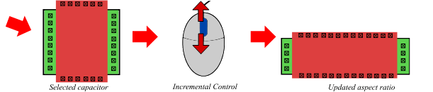 Figure 7 Capacitor transformation
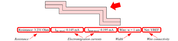 Figure 8 The selected wire electrical and physical properties displayed in the status bar [1]
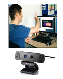 Figure 9 Gesture control mapped to the incremental interface
4. Gesture Control with Incremental Control
Discussed new control technique is compatible with the IC CAD environment and with current control devices such as keyboard, mouse, or track-ball. In addition to it is also compatible with new gesture tracking systems similar as in [5] and [6]. The Incremental Control is usually mapped to mouse wheel but has been experimentally mapped to gesture recognition camera Creative Senz3D using [7].
By using camera gestures “thumb up” and “thumb down” mapped to Incremental Control bindkeys, a wire width is updated as shown in Figure 9. Based on experience, when gestures were swapped or not recognized and had to be repeated, precision improvement of tested device must be put in place to be suitable for real analog layout application [1].
5. SKILL Implementation of Incremental Control
A flow chart describing the Incremental Control implementation in the programming language Cadence SKILL is shown in Figure 10. SKILL provides direct database access and allows environment customization as described in [3].
The program starts with a user action when the user selects a request type (RQT) by pressing a modifier and performs an increment or a decrement by the mouse wheel. Then the program detects the request type and information about the increment. After the request type and the increment detection, the check is performed, if objects are selected. When not, the program ends. When objects are selected, the program detects object IDs from the CAD (Computer aided design) database (CAD-DB) and reads the Incremental Control Database (IC-DB) which contains a list of changeable properties of each object type and determines the way of all possible modifications. For case of continuous values to be entered, the IC-DB also contains a list of predefined values which the program reads incrementally. If selected objects are members of the IC-DB, then the program loads actual values of the changeable properties from layout objects and loads technique of layout object modification from the IC-DB.
In some cases during layout object modification, an actual value of a changeable property can be slightly different than desired value in order to align layout objects to design grid. After repeated modifications, the actual value can shift from the desired value and a noticeable error can occur. Hence, an initial value of the changeable property is introduced. It allows that the actual value to be always calculated from the original correct value. Hereby the maximal possible accuracy of incremental changes done by the program is ensured. If the initial value is required and not yet set, the program stores the initial value as a parameter of the modified layout object and together with this also creates a record of the last updated value, which serves as a decisive criterion, whether the layout object has been changed in different way by this program.
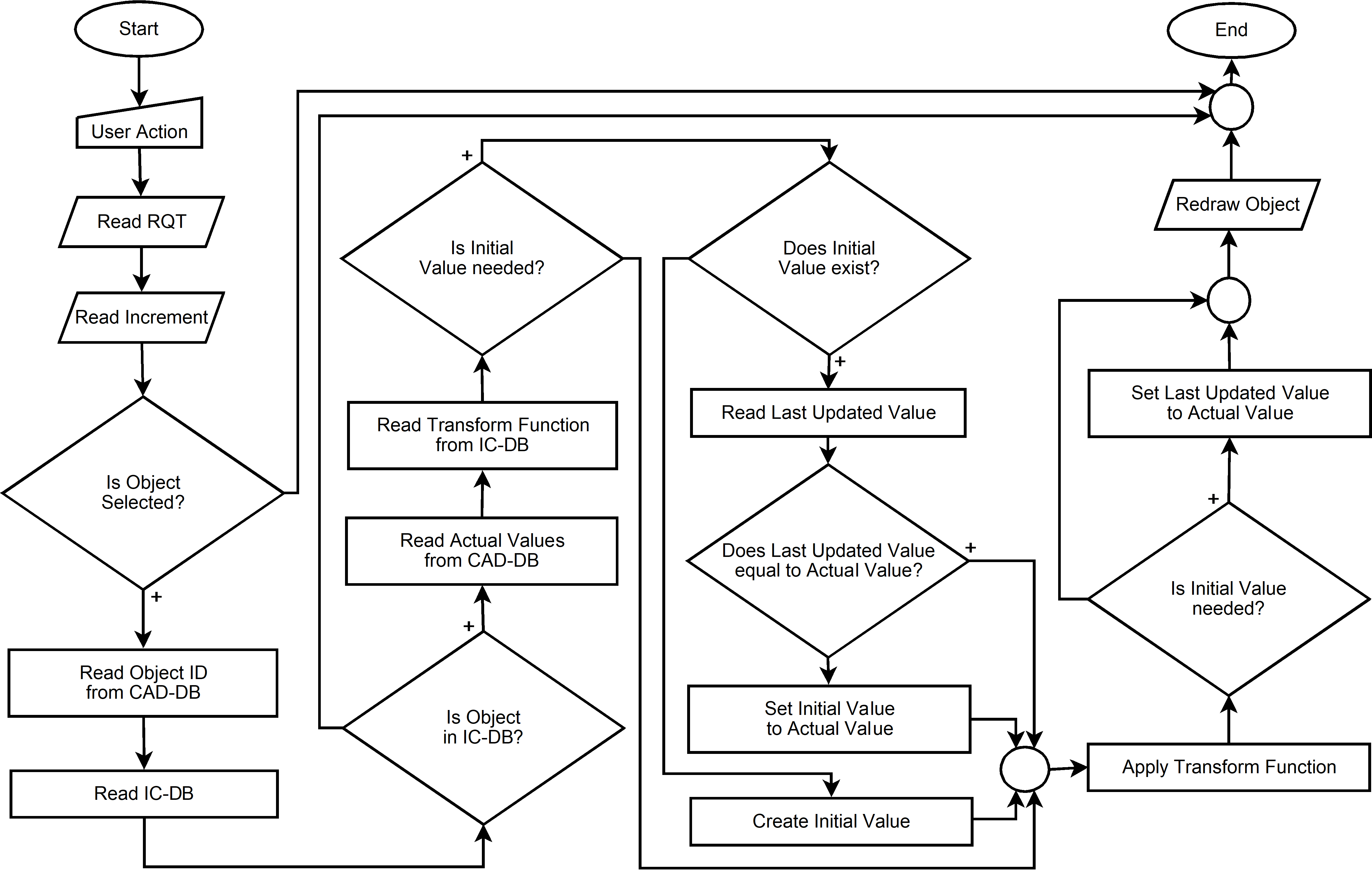 Figure 10 The flow chart of the Incremental Control
Table 1 Layout productivity measurement results [1]
| Layout object | tSC (s) | tIC (s) |
(tIC – tSC) / tSC (%) |
|
| via | 5.6 | 2.0 | -64.7 | |
| wire | 4.6 | 3.5 | -23.4 | |
| pin | 7.0 | 4.5 | -36.1 | |
| label | 5.8 | 3.5 | -39.9 | |
| pin + label | 15.1 | 5.0 | -66.7 | |
| rectangle | 5.2 | 3.2 | -38.5 | |
| transistor | 5.6 | 3.7 | -33.6 | |
| capacitor | 5.4 | 3.5 | -35.2 |
When the initial value is set, then is read and compared with the actual value. If these values equal, the layout object has not been modified by an external intervention and the initial value is untouched. If these values are different, the external intervention has been performed and the initial value is set to the actual value [1]. It means that the program respects the external intervention.
After these steps, update of a current state is executed based on obtained parameters and the function which has been read from the IC-DB. When the layout object initial value is mandatory, the last updated value is set to the actual value. So, the last updated value is the parameter of the layout object which allows that its value to be used in another run of this program. In the last step, the layout object is redrawn and the actual values are printed into the status bar. By cyclic applications of this program, the layout object is controlled incrementally. This program is able to operate with the OpenAccess and also with the CDBA databases.
6. Layout Productivity Gain
As already mentioned, the Incremental Control allows variety of different layout object modifications by intuitive common control concept. This concept reduces the number of actions needed to reach optimal result. To quantify layout productivity gain value, the average time of standard control modification tSC and of Incremental Control modification tIC to reach target value of layout objects are introduced. The measurement was performed under the same conditions and by a very experienced analog layout engineer with 14 years of experience. At least ten objects of each type were modified. Initial values of properties, which were changed, were set randomly for all objects. Then, the property values were modified to reach the target value by the both ways and the introduced durations tSC and tIC were measured.
Relative difference of tIC and tSC was used for calculation of average layout productivity gain for each layout object type. Based on measurement which is noted in Tab. 1, we can say that layout productivity time saving for the Incremental Control is in the range of 23 % to 66 %. From Tab. 1., it is evident that higher efficiency is reached when different objects are modified simultaneously.
7. Conclusion
The Incremental Control technique was developed to modify various database object properties. This control concept is very intuitive, hence it can be easily put into practice. The Incremental Control can be applied on different properties of database objects such as wires, pins, labels, vias, rectangles, MOSFETs, capacitors or other, which is the main advantage. Incrementally modified properties of objects can be controlled using keyboard, mouse or gesture tracking devices.
Main simplification of IC CAD modification flow is achieved due to removing of typing in object property window and replacing it by value increment. Additional time saving is achieved by suppression of pop-up Edit Properties windows for the most frequent operations. For additional flow improvement Incremental Control was mapped to mouse wheel. Then, productivity of analog layout has been improved in the range of 23 % to 66 %.
In advance, an alternative control was used experimentally when the Creative Senz3D gesture control camera was mapped to Incremental Control bindkeys. For example, width of wire was changed by “thumb up” and “thumb down” gestures. Based on our testing, the gesture tracking device still needs an additional improvement of precision to be suitable for analog layout creation.
Acknowledgment
This work is part of the CTU SGS grant no. SGS17/188/OHK3/3T/13.
- P. Vacula, V. Kotě, A. Kubačák, M. Lžíčař, R. Zelený, M. Husák, J. Jakovenko, “Incremental Control Techniques for Layout Modification” Advanced Semiconductor Devices & Microsystems (ASDAM), Smolenice, Slovakia, 2016.
- “Virtuoso® Layout Suite XL User Guide”, Cadence Design Systems, Product Version 6.1
- “Cadence® User Interface SKILL Functions Reference”, Cadence Design Systems, Product Version 6.1.6, August, 2015
- N. Munro, “ECSTASY – A Control System CAD Environment,” Proceedings of the International Conference on Control, 1988. CONTROL 88, Oxford, United Kingdom, April 13–15, pp. 76–80, 1988
- W. H. Chen, Y. H. Lin and S. J. Yang, “A generic framework for the design of visual-based gesture control interface,” Proceedings of the 5th IEEE Conference on Industrial Electronics and Applications (ICIEA), Taichung, Taiwan, June 15–17, pp. 1522–1525, 2010.
- D. Ionescu, B. Ionescu, C. Gadea and S. Islam, “An intelligent gesture interface for controlling TV sets and set-top boxes,,” Proceedings of the 6th IEEE International Symposium on Applied Computational Intelligence and Informatics (SACI), Timisoara, Romania, May 19–21, pp. 159–164, 2011.;
- “Intel® Perceptual Computing SDK – Human Interface Guidelines”, Intel Corporation, Revision 3.0, February 25, 2013, [cited 10. 3. 2016], available from: https://software.intel.com/sites/default/files/article/401008/perc- humaninterfaceguidelines.pdf.