Optimal Rotor Design of Line Start Permanent Magnet Synchronous Motor by Genetic Algorithm
Optimal Rotor Design of Line Start Permanent Magnet Synchronous Motor by Genetic Algorithm
Volume 2, Issue 3, Page No 1181-1187, 2017
Author’s Name: Bui Minh Dinha)
View Affiliations
Affiliation of electrical engineer, Department of Electronic electrical equipment, Ha Noi University of Science and Technology, Vietnam
a)Author to whom correspondence should be addressed. E-mail: dinh.buiminh@hust.edu.vn
Adv. Sci. Technol. Eng. Syst. J. 2(3), 1181-1187 (2017); ![]() DOI: 10.25046/aj0203149
DOI: 10.25046/aj0203149
Keywords: Line Start Permanent Magnet Synchronous Motor (LSPMSM), Induction Motor(IM), Genetic Algorithm (GA)

Export Citations
Line start permanent magnet synchronous motor (LSPMSM) is one of the highest efficiency motors due to no rotor copper loss at synchronous speed and self-starting. LSPMSM has torque characteristics of both induction motor IM and Permanent Magnet Synchronous Motor-PMSM. Using Genetic Algorithm (GA) for balancing magnetic cost and for copper loss minimization, the magnetic sizes and geometry parameter of stator and rotor are found and manufactured for industrial evaluation. This article is also taking account practical manufacturing factors to minimize mass production cost. In order to maximize efficiency, an optimal design method of cage-bars and magnet shape has to be considered. The geometry parameters of stator and rotor can be obtained by an analytical model method and validated by FEM simulation. This paper presents the optimal rotor design of a three-phase line-start permanent magnet motor (LSPM) considering the starting torque and efficiency. To consider nonlinear characteristics, the design process is comprised of the FEM and analytical method. During this study, permanent-magnets and cage bars were designed using the magnetic equivalent circuit method and the barriers that control all magnetic flux were designed using the FEM, and the tradeoff of starting torque and efficiency is controlled by weight function in Taguchi method simulation. Finally, some practical results have been obtained and analyzed based on a LSPMSM test bench.
Received: 06 March 2017, Accepted: 01 June 2017, Published Online: 20 July 2017
1. Introduction
Line start permanent magnet synchronous motor (LSPMSM) are well known as high efficiency motor due to outstanding advantages compared to other types of induction motor such as high efficiency [1-3], robust structure and high power density. LSPMSM has rotor cage and permanent magnet to maximum starting torque and efficiency because rotor bar loss will be minimized at synchronous operation. The LSPMSM can apply for many areas of ventilation and fan drives. Most of industrial drive motor can be replaced by LSPMSM high efficiency, it saves from 3 to 5% energy of total electric motor consumption. However, it has some drawbacks of starting torque and efficiency performance based permanent magnet sizes and rotor structure. The stator consists of stacked steel laminations with windings placed in the slots whereas the rotor is made of embedded permanent magnet that can vary from two to eight pole pairs with alternatenorth and south poles. In LSPMSM design, rotor magnetic structure has a significant effect of starting torque performances [4-6]. The torque of rotor cage is to speed up motor reach synchronous operation. The permanent magnet will pull rotor to synchronous speed with high efficiency. To maximize efficiency and starting torque, a practical optimal rotor structure have been implemented by Genetic Algorithm (GA) with different factors of cost, sizes and losses. The practical optimization is material and manufacturing cost of LSPMSM from 2.2kw to 11kW for mass production.
2. Basic parameter of LSPMSM
2.1. Electromagnetic design
Figure 1 Magnetic properties of NdFeB35In order to determine operation points of permanent magnet circuit, some basic parameters of magnetic circuit have calculated in an analytical model. This point depends on remnant flux density and silicon steel material. In this paper, the magnet of LSPMSM has been carried out by analytical model in fig 1 and NdFeB35 is magnet material used due to its good thermal stability and remnant flux density (~1.3T) allowing its use in applications exposed to high temperature about 1800C. The flux density is estimated about 0.88 T.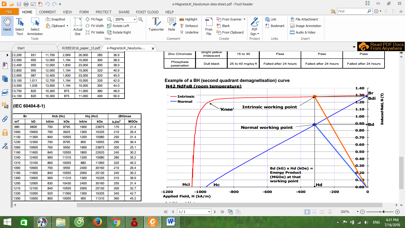
Based on the analytical method, some geometry parameters of stator and rotor can be calculated as follow chart in fig 2. An analytical model was undergone many calculation steps to define basic parameters. Based on torque volume density TVR from 20 to 30 kNm/m3 [5], if we assume rotor diameter equal to rotor length, the rotor diameter D and length L sizes of LSPMSM is determined as follow:
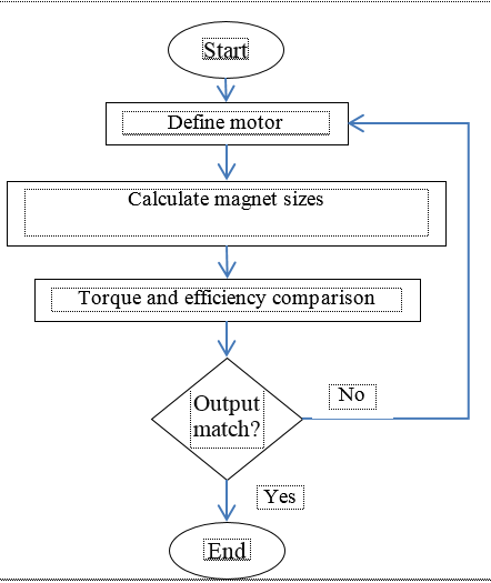 Figure 2 Calculation process
In general, the design process of LSPMSM is similar to that of induction motor. The main parameters (such as outer diameter, rotor diameter, motor length, stator slot, air gap length) are defined by taken into account some practical factors with desired input requirements [3]. The main part of the process is to design the rotor configuration which is embedded permanent magnet. The PM configuration needs to create sufficiently magnetic voltage for magnetic circuit. In fact, there are some possible configurations sorted by the shape and position of PM inside rotor as listed below:
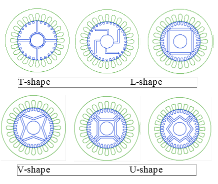 Figure 3 LSPM PM configurations
According to Ilhan Tairimer’s research in 2009 [4], the PM configuration has a great influence on motor efficiency. He also pointed out that the V-shape PM gives the highest efficiency. However, the decision on choosing PM configuration depends on the possibility of manufacturing it. In other word, the technique (includes the cost of procedure) and material properties are crucial criteria that impact the configuration selection. By considering them, the I-shape PM is applied in this design.
Table I. Motor parameters
| Parameter | Value | Unit |
| Air gap length | 0.5 | mm |
| Stator inner diameter | 155 | mm |
| Stator outer diameter | 240 | mm |
| Rotor outer diameter | 154 | mm |
| Rotor shaft diameter | 40 | mm |
| Rotor/stator length | 135 | mm |
| PM thickness | 8 | mm |
| PM width | 60 | mm |
| Number of PM piece | 4 | – |
| Stator slot | 36 | – |
| Slot space factor | 0.48 | – |
| Air gap flux density | 0.95 | T |
| speed | 1500 | rpm |
Copper and iron losses are determined efficiency and copper losses in stator winding are biggest, other losses are also calculated and shown in Table II.
Table II. Loss calculation
| Loss | Value | Unit |
| Copper loss | 160.5 | W |
| Stator teeth loss | 8.1 | W |
| Stator yoke loss | 7.6 | W |
| Bearing loss | 12.0 | W |
| Windage loss | 14.4 | W |
| Additional loss | 6.4 | W |
| Total loss | 219 | W |
| Efficiency | 94.5 | % |
Some layout of LSPMSM with I-shape are shown in fig 4 due to manufacturing technologies and high flux density in air gap of this rotor configuration.
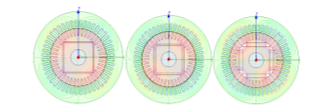 Figure 4 Layout of LSPMSM rpm with different magnet sizes
3. Optimal design of LSPMSM by genetic algorithm
To apply the GA approach, an objective function has to be defined to evaluate how good each motor design is. This objective function may include all the geometrical dimensions of the motor and a large subset of constraints (geometrical constraints) have to be formulated to ensure the physical feasibility of the motor. LSPMSM efficiency is determined as in (2):
With: is output power which is calculated by:
: motor speed in steady state (rpm) (determined by FEA)
: load torque in steady state (N.m) (determined by FEA)
is total loss in motor.
core loss in stator and rotor laminations (by FEA)
mechanical loss
additional loss
In order to evaluate efficient objective in 10 scale, the objective function is determined by the following:
When η = ηmin = 0 function value will be 10
η = ηmax = 1 function value will equal to 1
Second objective function is permanent magnet volume function.
Due to the motor is considered in 2-D planar environment, the permanent magnet (PM) volume calculation is transformed into PM cross-sectional area and PM stacking length is considered constant.
To evaluate this objective in 10 scale, objective function is determined by the following:
error of efficiency target
error of magnet volume target
weight factors.
Because the permanent magnet cost is more important than other components, the factors are selected =0.8 and =0.2.
4. Optimal results comparison
4.1. Optimized Program Results
Cost factors can be obtained from magnet sizes, based on those results, optimal design parameters will be determined in Table III.
Table III. Cost factor results
| No | Rib (mm) | Lm (mm) | Wm (mm) | |
| Cost | ||||
| 270 | 1.35 | 2.595 | 54.13 | 0.57922 |
| 323 | 1.828 | 2.615 | 55.03 | 0.58458 |
| 190 | 1.542 | 2.5 | 58.25 | 0.58826 |
| 273 | 1.756 | 2.657 | 54.27 | 0.58846 |
| 157 | 1.782 | 2.735 | 51.98 | 0.59382 |
| 320 | 1.887 | 2.57 | 58.45 | 0.60239 |
| 317 | 1.497 | 2.685 | 49.52 | 0.60727 |
| 327 | 1.313 | 2.622 | 57.71 | 0.60985 |
| 382 | 1.889 | 2.913 | 48.7 | 0.6134 |
| 301 | 1.281 | 2.926 | 49.09 | 0.61626 |
| 245 | 1.498 | 2.95 | 49.11 | 0.61809 |
| 184 | 1.002 | 2.92 | 48.25 | 0.61933 |
| 213 | 1.666 | 2.975 | 48.49 | 0.62213 |
| 123 | 1.483 | 3.062 | 46.76 | 0.63403 |
| 375 | 1.015 | 3.06 | 47.41 | 0.63436 |
| 282 | 1.923 | 2.818 | 55.09 | 0.63493 |
| 251 | 1.89 | 2.632 | 60.08 | 0.6444 |
| 221 | 1.087 | 2.785 | 47.14 | 0.64621 |
| 163 | 1.822 | 2.934 | 53.06 | 0.64817 |
| 244 | 1.679 | 3.188 | 44.48 | 0.65168 |
The optimized value distribution results are obtained by the following figure 5.
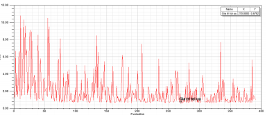 Figure 5 Distribution of optimized value of LSPMSM 7,5 kW
The optimized value is 270 which has the cost valued equals to 0.5792.
4.2. Revaluate optimized results
With the optimized results:
Rib = 1.35 (mm), Lm=2.595 (mm); Wm = 54.13(mm)
The volume has been decreased 2.5 times compared to original design, notice that PM depth is still unchanged.
In order to be convenient to compare, another results will be shown between before and after running optimization program.
After running simulation by electromagnetic circuit model with optimized parameters, the results are:
- a) Flux density and e.m.f
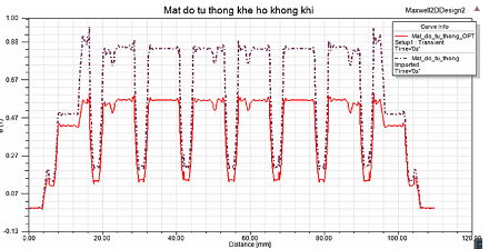 Figure 6 Air gap flux density before and after optimization
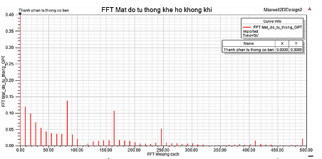 Figure 7 Fourier analysis for air-gap flux density before and after optimization
Air gap flux density after optimization is smaller than before due to the decrement of PM width. This proves motor doesn’t require large PM energy as before optimized results.
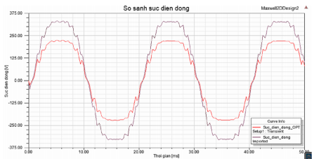 Figure 8 Comparison between e.m.f before and after optimization
Optimized e.m.f is smaller than before optimization corresponding to smaller air gap flux density. Electromagnetic force will cause negative effect of braking torque and dynamic characteristics will be better, faster starting time with the same load torque. In the other hand, peak wave shape will be smoother.
- b) Efficiency in transient mode
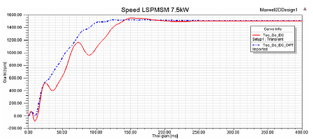 Figure 9 Comparison between speeds starting characteristic before and after optimization
Speed starting characteristic of LSPMSM 7.5 kW after optimization is much better than the previous value with faster stable speed and less ripple.
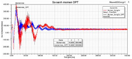 Figure 10 Comparison between speed starting characteristic before and after optimization
Torque starting characteristic of LSPMSM 7.5 kW after optimization is also better than before optimization value, with smaller torque ripple amplitude. It can also be considered from speed starting characteristic.
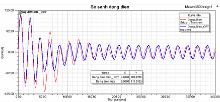 Figure 11 Comparison between starting current before and after optimization
From the figure, it can be seen that the starting current after optimization is smaller than the before value but higher steady-state value due to higher power factor.
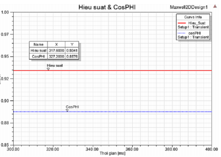 Figure 11 Efficiency and power factor after optimization
According to figure, it can be seen that, after optimization parameters provide higher efficiency. Smaller power factor is caused by the remarkable reduction in PM volume after optimization, however, the new value satisfies requirement that power factor has to be higher than 0.85.
5. Calculate temperature rise using thermal model
There are currently some thermal models can be applied to calculate operating temperature of motors. In this research, we chose Lump parameter model [5] to calculate temperature rise of 8 common motor nodes due to its uncomplicated method and rough precision.
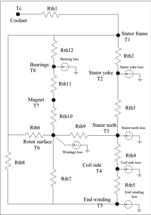 Figure 12 IPM thermal model network
For simplicity, it proposes some following assumptions [3]:
– The heat flows in the stacks only in the radial direction.
– The heat flows from the slots to the teeth but not directly to the yoke.
– The temperature of copper is assumed constant in every cross-section of the winding, but it varies in the axial direction.
– In the tooth, the temperature is assumed constant
in the axial direction.
– Resistive losses are distributed uniformly in the winding.
In order to evaluate the temperature rise, we firstly calculate individually thermal resistance of motor parts, which is affected by its material and parameters. Then by taking them into the following equation with particular losses, we obtain the temperature of each desired node:
Table IV Temperature calculation results
| Tc | T1 | T2 | T3 | T4 | T5 | T6 | T7 | T8 |
| 50 | 50.0 | 50.7 | 51.1 | 56.0 | 56.4 | 68.8 | 71.0 | 71.2 |
If the coolant temperature is assumed to be 50 0C, temperature of the hottest points (usually the permanent magnet and bearings) are under 71 0C. That means with air cooling, the temperature rise is 21 0C at maximum. This result allows the PM to operate well and gets rid of demagnetization.
However, this design is still not really reliable. To validate the design, we’ll input all these parameters into RMxprt to see if the output is matched or not.
Using all the calculated parameters and initial input (rated speed, rated voltage, rated output power) as input for RMxprt, we obtained the operating statistic of the motor. Because the design of permanent magnet can have major influence on the motor. An insufficient size of PM could force the magnet to operate in higher flux density which is not recommended or even not adapt the rated output power if the value exceeded remnant flux. Thus, what we must care most about are output power, RMS line current, efficiency and magnetic data.
6. FEM Model Results
FEM has been applied to investigate magnetic performance of LSPMSM design. The flux density of stator and rotor has been validated by FEA model for one pole in fig 5. Flux density curve vs rotor angle is shown in fig 6. Average values are 0.5 tesla in good agreement with calculation.
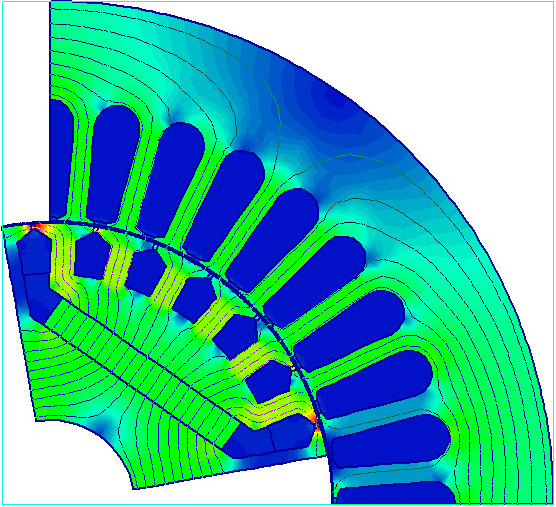 Figure 13 Flux density distribution
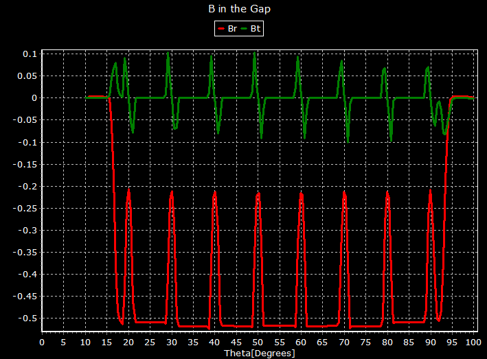 Figure 14 Flux density in air gap results
Magnetic circuit is obviously not saturated and magnet flux density is also adequately high. That allows the motor to operate in overload mode which has not been defined yet.
Torque and efficiency of LSPMSM design play an important role on implementation of this motor. The torque curves of rotor cage, magnet and motor are shown in fig 7.
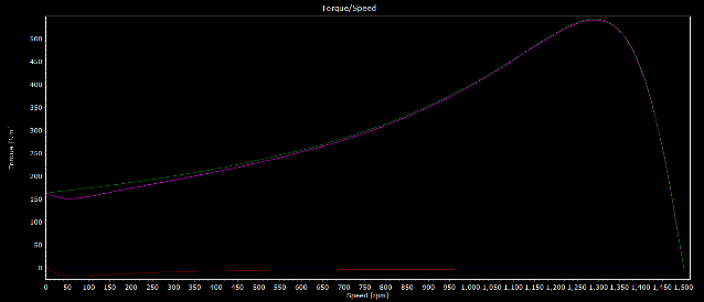 Figure 15 Torque of cage, magnet and motor results
Efficiency of 91% with 10% overload in fig 8. The power shaft is 8 kW started direct from grid. From those results can be concluded that LSPMSM is higher efficiency with IE 2, 3 than induction motor. Total cost of LSPMSM is more expensive than IM but lower operation cost of electric energy can help LSPMSM payback in short time.
Temperatures of rotor and stator tooth, yoke and windings have been calculated under natural convention. The results of analytical and model are good agreements.
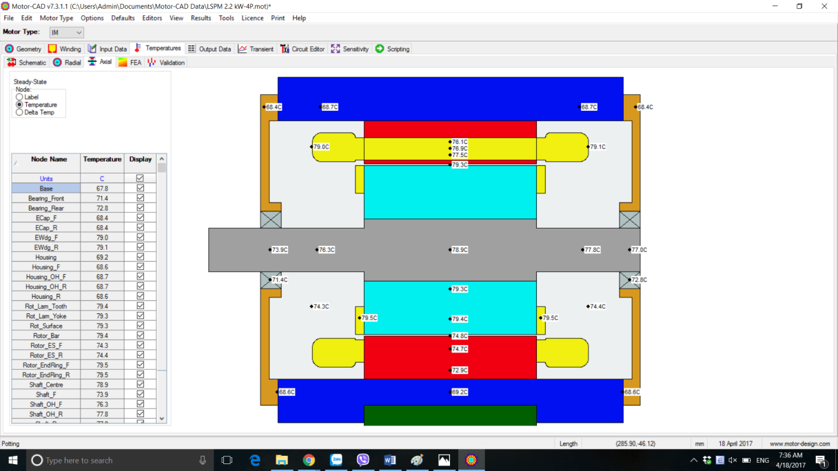 Figure 18 Temperatures of stator and rotor
7. Hardware test bench setup
Rotor magnetic slots have manufacture by wire cutting after die-casting rotor bars and shaft assembly as fig 9.
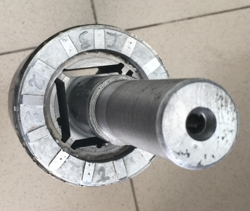 Figure 16 Rotor magnet slots
The whole hardware of LSPM motor was built together as fig 10.
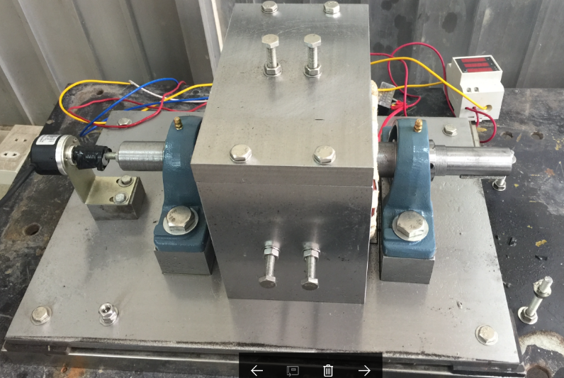 Figure 17 Hardware of LSPM motor
In order to control air gap of rotor and stator, adjustable screw have used to change stator position in three sides. The rotor shaft was connected to encoder to measure speed of motor though NI card and LabVIEW software. Especially, it can measure the dynamic speed performances to validate period of time for speed synchronizing. The LSPM motor was setup to evaluate synchronizing speed under different load and voltage by autotransformer of 10 kW. The transient time for constant speed is less than 0.8 second.
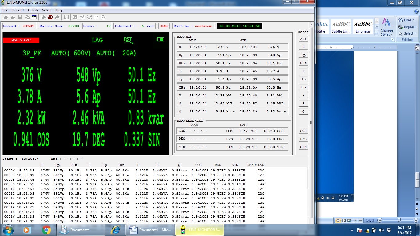 Figure 19 Experiment results of LSPMSM test
8. Conclusion
The paper has presented a comprehensive design of a LSPMSM for industrial applications. The design was calculated by analytical method, validated by Ansysmaxwell software. Particularly, thermal calculation was carried out to assure that the permanent magnet cannot be demagnetized under steady operation. Optimal design parameters have been calculated by GA program. Those results have evaluated by analytical and model methods. The hardware test bench has been built to evaluate synchronizing speed under different loads. The GA program results are LSPMSM design and manufacture cost with lowest price for mass production similar induction motor prices and transfer to industrial companies.
Acknowledgment
This research was supported the National Research Foundation of Vietnam funded by the Ministry of Science and Technology under Program KC.05/16-20.
- Kwangsoo Kim; Seung Joo Kim; Won Ho Kim; Jong Bin Im; Suyeon Cho; Ju Lee, “The optimal design of the rotor bar for LSPMSM considering the starting torque and magnetic saturation”,Electromagnetic Field Computation (CEFC), 2010 14th Biennial IEEE Conference on Year: 2010.
- Sorgdrager, A. J.; Wang, R-J.; Grobler, A. J. “Transient performance investigation and Taguchi optimization of a line-start PMSM”, Electric Machines & Drives Conference (IEMDC), 2015 IEEE International, On page(s): 590 – 595.
- A.H. Isfahan, S.V. Zadeh (2011) Effects of Magnetizing Inductance on Start-Up and Synchronization of Line-Start Permanent-Magnet Synchronous Motors. IEEE Transactions on magnetics, vol. 47, no. 4.
- A.H. Isfahani, S.V. Zadeh, M.A. Rahman (2011) Evaluation of Synchronization Cappability in Line Start Permanent Magnet Synchronous Motor. IEEE International Electric Machines & Drives Conference.
- J.R.Hendershot, T.J.E. Miller. “Design of brushless Permanentmagnet motors”. Magna Physics publishing and Clarendon press-Oxford1994.
- P. Ji, W. Song,andY.Yang, “Overview on application ofpermanent magnet brushless DC motor,” Electrical MachineryTechnology,vol.40, pp.32-36,Feb.2003.
- John Wiley & Sons Ltd, “Design of rotating electrical machines”, 2008, The Atrium, Southern Gate, Chichester, West Sussex, PO19 8SQ, United Kingdom.
- Ilhan Tarimer (2009), “Investigation of the Effects of Rotor Pole Geometry and Permanent Magnet to Line Start Permanent Magnet Synchronous Motor’s Efficiency”, Muğla Turkey.
- Joachim Lindstrom, “Thermal Model of a Permanent Magnet Motor for a Hybrid Electric Vehicle”, April 1999, Department of Electric Power Engineering, Chalmers University of Technology, Goteborg, Sweden.
- Soo-whang Baek, Byung-taek Kim, and Byung-il Kwon,”Practical Optimum Design Based on Magnetic Balance and Copper Loss Minimization for a Single-Phase Line Start PM Motor” IEEE TRANSACTIONS ON MAGNETICS, VOL. 47, NO. 10, OCTOBER 2011.