A Novel Ultra High Speed and Configurable Discrete Wavelet Packet Transform Architecture
A Novel Ultra High Speed and Configurable Discrete Wavelet Packet Transform Architecture
Volume 2, Issue 3, Page No 1129-1136, 2017
Author’s Name: Mouhamad Chehaitly1, Mohamed Tabaa2, a), Fabrice Monteiro1, Abbas Dandache1
View Affiliations
1Laboratoire LGIPM, équipe ASE, Université de Lorraine, Île du Saulcy, 57045 METZ, France
2Laboratoire Pluridisciplinaire de Recherche et Innovation (LPRI), EMSI, Casablanca, Morocco
a)Author to whom correspondence should be addressed. E-mail: med.tabaa@gmail.com
Adv. Sci. Technol. Eng. Syst. J. 2(3), 1129-1136 (2017); ![]() DOI: 10.25046/aj0203142
DOI: 10.25046/aj0203142
Keywords: DWPTMallat-tree algorithm, Embedded Systems, FPGA, Parallel Architecture, VHDL-RTL modeling

Export Citations
This work is dedicated to present a new pipeline-parallel architecture of Discrete Wavelet Packet Transform (DWPT) for all wavelet family implemented in FPGA technology. The main target of our architecture is to provide an effective performance trade-off, where it significantly increases the throughput with a restricted amount of hardware. In this article, we propose two kinds of configurable architecture: first architecture with a very strict amount of hardware base of pipeline and sharing resource, and the second architecture provide an ultra-high speed by propose P-parallel DWPT and a parallel direct FIR filter under the strategy of pipeline-parallel and sharing resource. The pipeline and the clever sharing of the hardware resources are smartly connect based on low-pass and high-pass filters in the Mallat-tree algorithm. These architectures are fully configurable in synthesis according to parallel degree, the tree depth (number of tree levels), the order of the filters and the filter quantization coefficient. Consequently, the simulation results accelerated to an approximate value of P*(Frequency). Furthermore, the tree depth and filters order has little impact (only due to place and route variations) on throughput. This architecture was synthesized using Altera Quartus prime lite edition targeting an Altera Cyclone IV – (FPGA) and it was developed in VHDL at RTL level modeling.
Received: 26 April 2017, Accepted: 15 June 2017, Published Online: 16 July 2017
1. Introduction
From the work of Coifman and Wickerhuaser in 1992, the wavelet packet transform has a lot of attention from both academic and industry establishments. Where in the literature, we found a lot of research dedicated of wavelet packet transform and there implemented in different domains: communication, image, video, data compression, wireless sensor network and other. But in the last years, we saw a rise in the amount of data that needs to trait and transmit. That requires a new throughput level and need a new platform or program logic device (PLD), which can provide a high speed, with low cost and low power consummation.
In this context, the first work try to implement the DWPT on processor was recorded in 1999 by [2]. However, DWPT (based of FIR filter banks) complexity makes it hard to fulfill high throughput and low area (Material resource) consumption. To provide these constraints, we find many works dedicated of the implementation of DWPT on FPGA like [3-16]. The powerful of Discrete Wavelet Packet Transform (DWPT) is due to the ability of represent both transient and stationary behaviors of data signal by a few of transform coefficients. The most implemented solution of wavelet transform is based on the FIR (Finite Impulse Response filter) filter banks concept [1]. To benefit as maximum possible of this characteristic, many works have addressed the implementation of DWPT in hardware device like processor or FPGA.
The architecture of Daubechies wavelet on scale 6 (DB6) based on algebraic integers is proposed in [3], the authors have developed architectures for one and two dimensions of DB6 with minimization of the number of used adders.
An integrated systolic architecture for computation of the 1-D of DWPT/IDWPT are presented in [4] where the architecture can limited the number of page requirements. In [5], DWPT/IDWPT are implemented using Embedded Instruction Codes (EIC) where the authors used two multipliers and four adders for the symmetric filters. [6] presented a word-serial pipeline architecture and parallel filter processing for DWPT/IDWPT. The same authors are followed their work in [7] where they are used high-pass and low-pass filters to speed up transformation. Then, the same authors are also developed the implementation of the wavelet packet transform on FPGA with three types of multipliers in [8]. In 2006, [9] presented a word-serial pipeline architecture with a new parallel FIR filter processor to perform the DWPT/IDWPT transform. And between the years 2013-2014, [10] presented a flexible architecture of DWP/IDWPT based directly on the registers and on an efficient multiplexing structure.
Another architecture of DWPT implement the tree search algorithm is presented in [11], then their implementation on FPGA is discussed in [12]. The same authors in [13] have developed parallelized architectures in two modes: serial-word and parallel- word of the direct and inverse DWPT transform.
The authors in [14] was proposed an architecture for implementing fast and configurable DWPT based on FIFO inputs, dual-port memory, multipliers and adders. [15] also presented a hardware design of DWPT based of frame-partitioned architecture. And in our previous work [16], we propose a fast and reconfigurable architecture but non parallel of DWPT.
This paper proposes a novel P-parallel (Parallel degree P) architecture of DWPT transform and also reconfigurable, based on the Mallat tree scheme [17], with a parallel direct FIR bank filter structure. It is very suitable for the implementation in global parallel DWPT architecture. The architecture aims to offer a suitable compromise between computational performance (throughput rate) and resource consumption (area cost). The core of our architecture is flexible and can provide an elegant sharing of computational resources (multipliers and adders) between the approximation and details related filter banks. The architecture is fully configurable in synthesis according to parallel degree, the tree depth (number of tree levels), the order of the filters and the filter coefficient quantization.
This paper describes in section II a brief theory of the wavelet and wavelet packet transform concepts. In section III, we propose our DWPT architecture compared with the results obtained from HDL coder. Our proposed P-parallel DWPT architecture in section IV. That summarizes the results obtained for this architecture on a FPGA implementation and compared with other previous work in literature. Finally in section V, we will set forth the conclusion part.
2. Review of wavelet packet transform
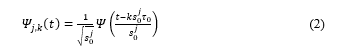
In the wavelet transform theory, a signal x(t) is decompose by projecting it into a family of functions , all derived obtained from the same original single function called “Mother wavelet” by translation and dilation or contraction:
where . For large , the basis function becomes a stretched version of the prototype wavelet, that is a low frequency function, while for small , the basis function becomes a contracted wavelet, that is a high frequency function.
Therefore, the discrete wavelets transform (DWT) are discretely scalable and translatable. This was achieved by modifying the wavelet representation in (1) to create Daubechies (1992) [18]:
 So the Discrete Wavelet Transform (DWT) of signal present in (3):
![]()
DWT can be implemented by the convolution operation between signal and mask . But also, DWT can be implemented by non-uniform filter banks. Where the input signal separates into low frequency component signal and high frequency component signal. The first is called smooth coefficient while the second part is called wavelet coefficients. The smooth coefficient is separated into two parts repeatedly. In the classical way, we indicate the two parts via low-pass digital filter H and a high pass-filter G. By using the scaling function and there corresponding mother wavelets, we obtain both digital filter H and G. We suppose H and G like a FIR filters non-recursive with L length, the transfer functions of H and G can be expressed as:
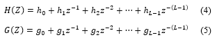 Mallat’s tree algorithm or pyramid algorithm [19] can be used to find the multiresolution decomposition of DWT, the two scale relations (4) and (5) leads to scaling functions and wavelet functions similar to that in scalar wavelets. But the equations are two scale matrix equations and can be given as:
 Where and forms the set of scaling functions and corresponding wavelets. The suffix r denotes the number of wavelets and is dubbed as multiplicity.
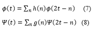
 Figure 1. Three-level DWPT decomposition tree
3. Our proposed architecture N°1: smart sharing and pipeline architecture
In the recent work, the most important challenge for developer is design a new DWPT architecture can ensure high speed data processing with low consummation resource. That leads to minimize the needed energy and size hardware (critical constraint in many application domain like WSN, Body area Network, and others).
3.1. Fast and reconfigurable architecture unparalleled
To answer of their challenge, we are developed in the first time in [16], our first fast and configurable DWPT architecture based of Mallat tree approach (Figure 1) and transposed digital FIR filters in the filter banks.
In Figure 2, we present the proposed unparalleled-pipeline architecture. That take advantage of this present in original Mallat tree where instead using a classic FIR filter in stage k (the amount of data to be processed by any filter of stage k is × the amount to be processed the filter or stage 1.), only one modified filter is implemented. The power of modified proposed filter can process all data in the same stage k and serve the functionality of low-pass filter and high pass in the same time.
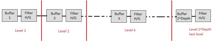 Figure 2. Block view of the proposed DWPT architecture datapath.
In each level, the simple architecture is based of two blocks: block “Buffer” and block d’un modified FIR filter “Filter H/G”. The structure of the block buffer is shown in Figure 3. As her name buffer block, it is built up on two shift register: fast shift register represented by “Fast buffer” and slow shift register represented by “Slow buffer”. An important characteristic of these blocs are the dynamic size i.e. the size of the block buffer depends on the stage k (where k parameter in the figure 2 and 3 is related to the number of the stage in which the buffer is implemented, example for k=1, we implement the first block buffer). The working mechanism of block buffer is the key word in our architecture where each buffer is built up as we mention bellow on two shift register of positions: a fast shit buffer that takes its data from the previous stage, and a slow buffer that feeds its own stage filter. The “fast buffer” achieve one shift on each clock while the slow buffer shift rate is one shift on each two clock cycles. As we show in figure3, the signal controls the rate of slow buffer registers. And the signal is driven on each cycles, all the data in the fast buffer in parallel to the slow buffer.
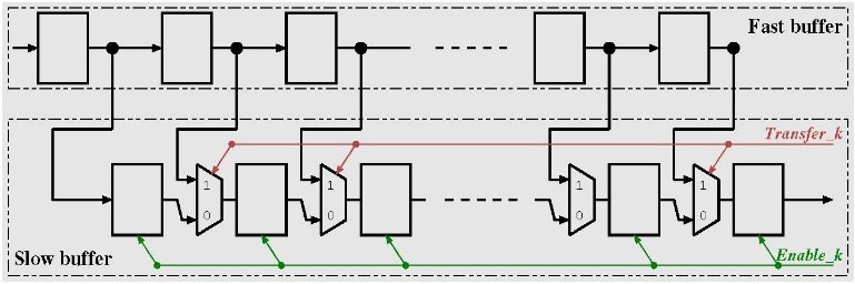 Figure 3. Block view of the buffers in stage k.
In Figure 4, are the modified blocks filters, they play the function of high pass filter and low pass filter and they are related to and , in equation (4) and (5), respectively.
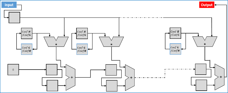 Figure 4. Architecture of a single modified FIR filter.
A control unit (figure 5) was also proposed in our work, to manager the BUFFER block and H/G FITLER block, we used a central CONTROLLE block provides the and signals to the related stage.
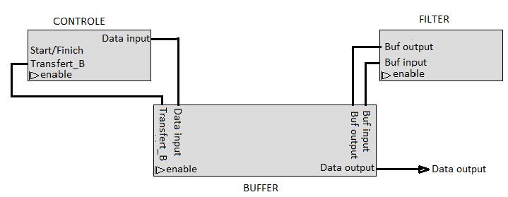 Figure 5. Overall view of the architecture with the central control block.
3.2. Results and synthesis
This proposed architecture was writing in VHDL-RTL modeling and we make a big effort to write a generic VHDL code (i.e. independent of target FPGA hardware). The synthesize of our architecture has been done by using Altera Quartus prime lite edition and it is targeted onto Altera FPGA belonging to Cyclone IV family. As we mentioned in [16], the architecture is fully configurable at synthesis in respect to the tree depth (number of tree levels), the order of the filters and the filter coefficient quantization.
Table 1. Implementation results of unparalleled DWPT
| Design parameters | Clock frequency | Resource usage |
| (2, 2, 5) | 207.68 | (158, 74) |
| (3, 2, 5) | 194.93 | (252, 130) |
| (4, 2, 5) | 200.28 | (397, 233) |
| (2, 4, 5) | 205.25 | (296, 114) |
| (3, 4, 5) | 181.23 | (446, 180) |
| (4, 4, 5) | 187.69 | (647, 293) |
| (2, 16, 5) | 178.99 | (1103, 354) |
| (3, 16, 5) | 179.73 | (1598, 480) |
| (4, 16, 5) | 170.36 | (2138, 653) |
| (2, 2, 16) | 104.14 | (857, 228) |
| (3, 2,16) | 101.31 | (1332, 405) |
| (4, 2,16) | 104.94 | (1940, 717) |
| (2, 4,16) | 102.54 | (1676, 356) |
| (3, 4,16) | 102.54 | (1676, 356) |
| (4, 4,16) | 92.06 | (3473, 909) |
| (2, 16,16) | 106.73 | (1609, 1108) |
| (3, 16,16) | 109.66 | (2250, 1493) |
| (4, 16,16) | 111.96 | (3032, 2013) |
Table 1, we obtained the result of needed area (consumption) and clock frequency for different values of the configuration parameters. In the table, design parameters are presented as a 3-tuple, depth (depth of Mallat tree), order (filter order), and quantization (number of bits of coefficient quantization). Clock frequency is given in MHz. And the resource usage is given as a 2-tuple, (le, lr) where le stands for logic elements and lr for logic registers.
3.3. Results obtained by HDL Workflow Advisor tools
In the last years, many tool are developed to facilate the designer work and to optomize the generate VHDL code of circuit. One of the important tools is HDL Workflow Advisor, this tool is developed by Mathwork society and it built in MATLAB/SIMULINk software. The aim in this section is to evaluate our unparalleled architecture by compare the results in table 1 with that obtained from optimizer HDL tool.
We developed a Simulink model of the some functional architecture of DWPT and then we are generated the optimized HDL code by using the HDL Workflow Advisor. The obtained VHDL code has been synthesized using the same software (Altera Quartus prime lite edition) and also target the same FPGA. The implementation results are present in table 2.
The synthesis in respect the parameter presented below in part B. but we add as result a furthest colon present the needed DSP block.
Table 2. Implementation results of DWPT from Simulink / Quartus.
| Design parameters | Clock frequency | Resource usage | DSP block |
| (2, 2, 5) | 286.29 | (18,25) | 0 |
| (3, 2, 5) | 207.25 | (29,38) | 0 |
| (4, 2, 5) | 127.29 | (54,70) | 0 |
| (2, 4, 5) | 134.66 | (29,41) | 0 |
| (3, 4, 5) | 96.72 | (48,62) | 0 |
| (4, 4, 5) | 64.24 | (88,110) | 0 |
| (2, 16, 5) | 31.2 | (155,262) | 12 |
| (3, 16, 5) | 21.66 | (425,606) | 28 |
| (4, 16, 5) | 14.03 | (818,1380) | 62 |
| (2, 2, 16) | 216.5 | (44,69) | 0 |
| (3, 2,16) | 165.4 | (74,104) | 0 |
| (4, 2,16) | 102.01 | (131,180) | 0 |
| (2, 4,16) | 103.77 | (142,129) | 0 |
| (3, 4,16) | 76.58 | (258,210) | 0 |
| (4, 4,16) | 50.36 | (606,439) | 0 |
| (2, 16,16) | 26.37 | (839,823) | 12 |
| (3, 16,16) | 20.65 | (1985,1915) | 28 |
| (4, 16,16) | 12.63 | (4449,4361) | 62 |
Base of implantation results presented in table I and II. It can easily make a comparison between our proposed architecture and other one from HDL tool. The synthesis of our architecture is done without any needed of DSP block when the optimized architecture (code) from Matalb/Simulink need from 12 to 62 DSP blocks depended of design parameters. When we increase the order of quantization from 5 to 16 that decrease approximately 50% the clock frequency but that decrease the Clock frequency to 95.5% with the optimized DWPT architecture by coded HDL tool from Matalb/ Simulink.
4. Our proposed architecture N°2: Parallel-Pipeline architecture with sharing resources
In this section, we propose a high throughput parallel architecture for DWPT, base of Mallat tree approach and using the direct P-parallel digital FIR filters in the filter banks. Figure 1 present a three-level decomposition tree for single parallel degree that provides eight frequency bands with P parallel degree. The filter bank consists of wavelet functions as the low pass filter and its dual high-pass filter
Considering the diagram in figure 6, the needed resource with classic Mallat tree is multiply by P. For example with degree of parallelism P=10 and depth=3, we need , we need 140 low/high pass filters where is a huge number. Furthermore, it can be observed that the data rate on any filter of given stage of the Mallat tree is just half the rate of any filter of the adjacent stage in input side, and twice the rate of any filter of the adjacent stage on the output side (factor 2 under-sampling from stage to stage). Indeed, instead of implementing low pass filters and low pass filters on bank filter stage , only one and just modified one filter is implemented. As we show in figure 7. It is important to mention that modified single filter (Block Filter H/G) will have to process all the data that would have been otherwise processed by the original filters of stage .
The structure for the modified filter is shown in figure 8. It follows the basic scheme. The main difference with the original filters is related to the handling of the filter coefficients and a smart shift to serve P sampling in each clock cycle. Respect the buffer order, it is the most sensitive and it is the core of the serial FIR filter to parallel operation. The diagram of P-input of n-tap transposed FIR filter as shown in Figure 4. Similar to coding theory, the Serial direct FIR filter is like a single-input single-output ( ) system and parallel direct FIR filter is like a multiple-input multiple-output ( ) system. Each clock cycle, there are P parallel inputs signals, hence P outputs signals.
In our proposed, we don’t have a limited of degree of parallel but it is necessary to choose degree of parallelism equal where . The choice of is pivotal to organized data between different level.
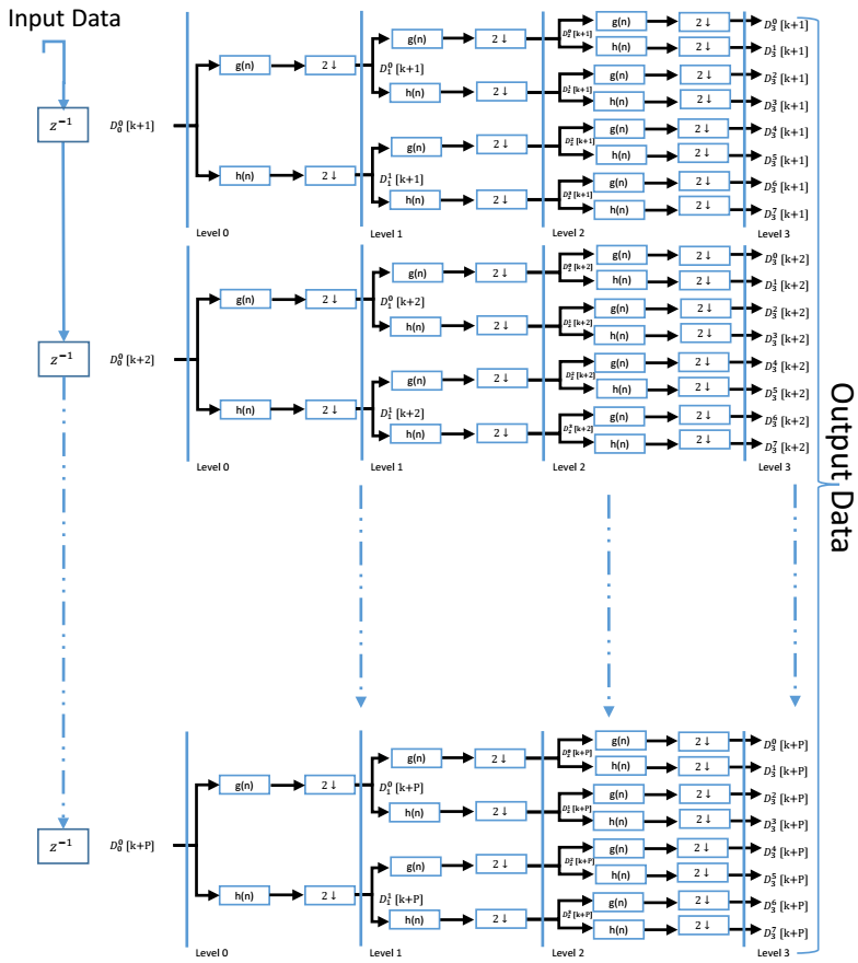 Figure 6 – P-parallel, Three-level DWPT decomposition tree
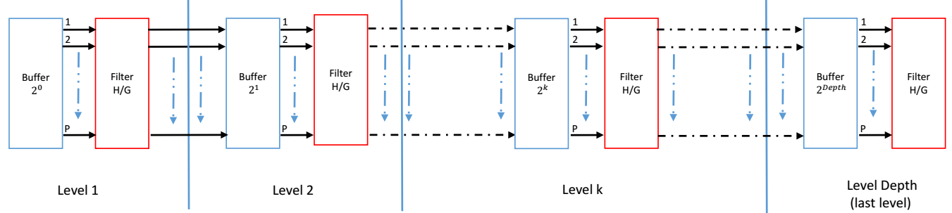 Figure 7. Block view of the proposed parallel DWPT architecture datapath
In Figure 8, is the high pass filter and low pass filter and they are related to and , in equation (4) and (5), respectively. Instead of using two filter with the same architecture, we use an alternatively process. Hence, the alternatively process (on consecutive cycles) force each filter to take a sample for the and the for and so on. This requires the filter to be feed by correctly scheduled data. This role is devoted to the buffers situated between the filters. The structure of a single buffer is shown in figure 9. The k parameter in the figure is related to the number of the stage in which the buffer is implemented. Then in each level k, the buffer is built up on two shift register of positions: a fast shit buffer that takes its data from the previous stage, and a slow buffer that feeds its own stage filter. And in global, the size buffer depends on parallel degree P and level k in which it is implemented. From its name fast buffer, it is fast than “slow buffer”. The “fast buffer” achieve P-shift on each clock while the slow buffer shift rate is P-shift on each two clock cycles. To manage this latency, we use enable signal called “ ” xhich was driven the slower shift rate. For fast buffer, we used a counter signal equal control the signal which every cycles; all the data in the fast buffer is transferred in parallel to the slow buffer. This transfer operation its done P times on each stage.
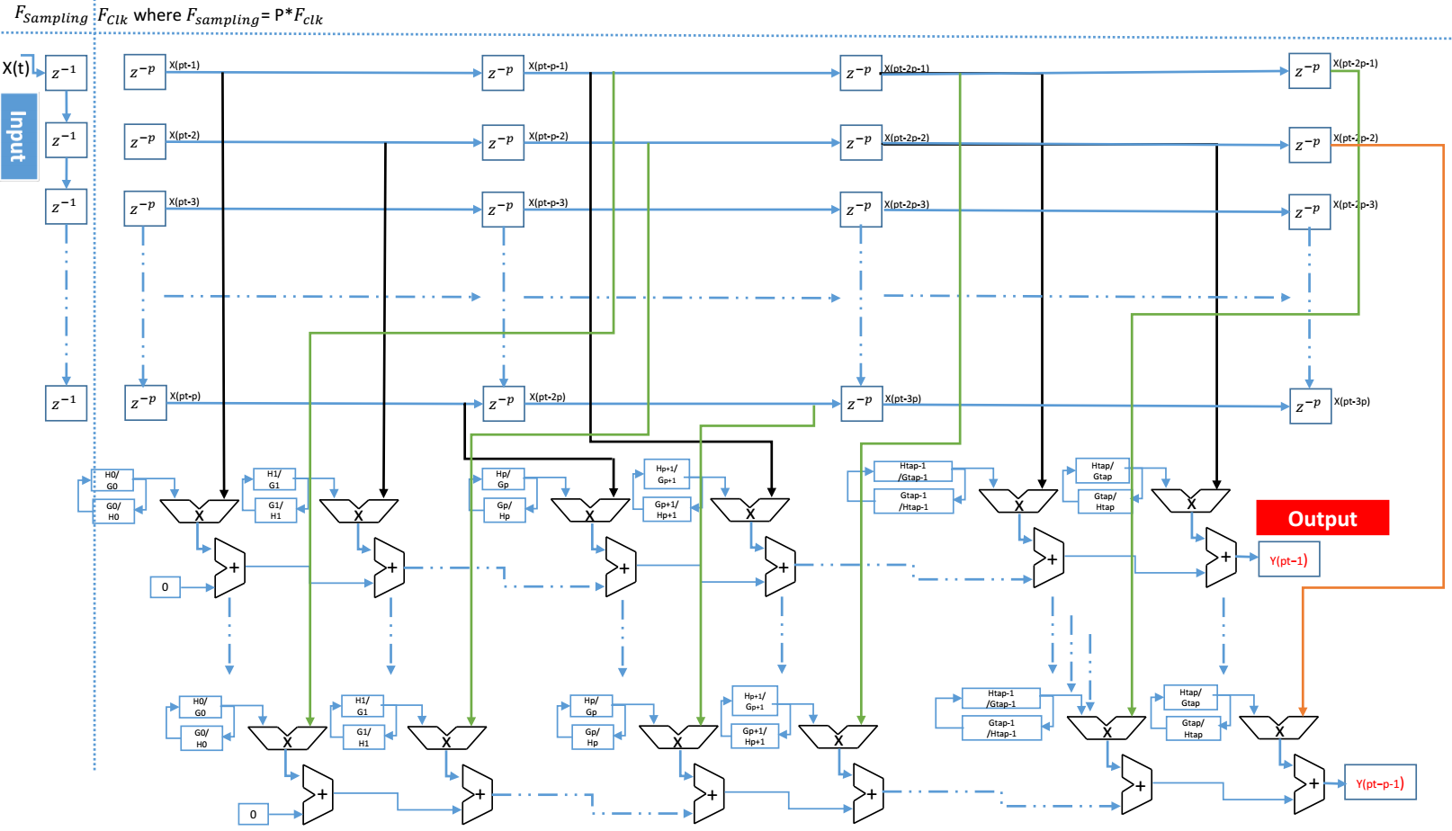 Figure 8. Architecture of a single modified FIR filter
Actually, we used those two signals and allowing P-times on each stage to combine the down-sampling ( ) and to synchronize (sample selection/ordering) output data on stage (k-1) with input data on stage (k), because we respect the same samples in the original Mallat tree. In this new scheme, the output of all the related stage filters are stored together in the fast buffer (and hence in the slow buffer too) in an interleaved ordered disposition. Only half of the samples can be transferred from the fast to the slow buffer on each cycles as the buffers size is only half the number of samples being feed to the fast buffer during the same period of time. Furthermore, each sample flowing out from the fast buffer must be presented twice to the next stage in order to be processed by both the and sets of coefficients. This is granted by the low rate of the slow buffer. A control unit is used also like that used in figure 5 to manage different stage, and the interleaved on every stage called . used to provides the and signals to the related stage.
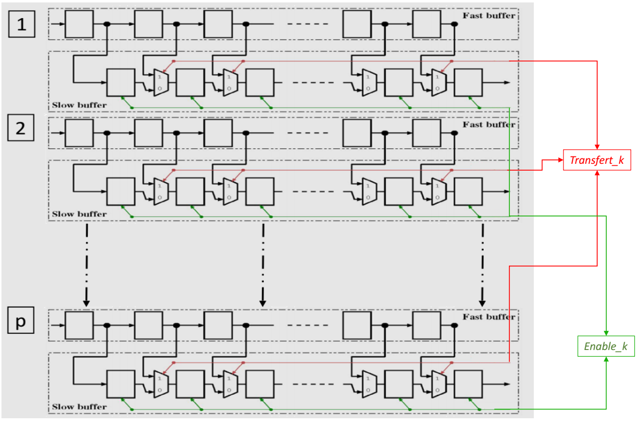 Figure 9. Structure of the buffers in stage k
4.1. Results and performances
The prove of the potential of our architecture isn’t stop in the parallel features but also this architecture is fully configurable, so at synthesis the implementation structure diagram have implemented under four parameter: parallel degree (rate of parallelism), tree depth (number of tree levels), the order of the filters and the filter coefficient quantization. We presented the real hardware implementation of our architecture onto Altera 5CGXFC9E6F35C7 FPGA belonging to Cyclone V family with a speed grade of –7 and we have synthesized it by using Altera Quartus prime lite edition. The compilation results of clock frequency and area consumption for different values of the configuration parameters, i. e. Tree depth, Filter order, Coefficient quantization (in number of bits) will presented in table 1 and table 2 of two different parallel degree. In those table, design parameters are presented as a 3-tuple ( ). Clock frequency is given in MHz is directly related to input sampling rate (half the clock frequency). Resource usage is given as a 2-tuple ( ) where stands for logic elements and for logic registers.
Although the highest rate of our architecture isn’t required any memory or DSP block. All results of implementation 4, 8 and 16 parallel DWPT is presented in Table 3, 4 and 5 respectively.
Table 3. Implementation results of 4-parallel DWPT
| Design parameters | Clock frequency | Resource usage |
| (2, 2, 5) | 415.36 | (471,296) |
| (3, 2, 5) | 400.86 | (756,510) |
| (4, 2, 5) | 389.56 | (1204,899) |
| (2, 4, 5) | 403.52 | (879,456) |
| (3, 4, 5) | 342.46 | (1299,719) |
| (4, 4, 5) | 375.24 | (1941,1171) |
| (2, 16, 5) | 357.99 | (3299,1416) |
| (3, 16, 5) | 369.83 | (4794,1924) |
| (4, 16, 5) | 3425.69 | (6397,2614) |
| (2, 2, 16) | 208.14 | (2571,905) |
| (3, 2,16) | 198.62 | (4216,1599) |
| (4, 2,16) | 209.89 | (5850,2853) |
| (2, 4,16) | 201.18 | (5038,1324) |
| (3, 4,16) | 194.60 | (7521,2260) |
| (4, 4,16) | 184.120 | (10374,3636) |
| (2, 16,16) | 180.41 | (4902,4402) |
| (3, 16,16) | 220.31 | (6805,5729) |
| (4, 16,16) | 213.63 | (9107,7752) |
Table 4. Presents the results of 8-parallel DWPT architecture
| Design parameters | Clock frequency | Resource usage |
| (2, 2, 5) | 583.03 | (1109,504) |
| (3, 2, 5) | 557.23 | (1699,935) |
| (4, 2, 5) | 562.25 | (2754,1531) |
| (2, 4, 5) | 586.20 | (2120,897) |
| (3, 4, 5) | 506.77 | (3050,1197) |
| (4, 4, 5) | 526.91 | (4603,2023) |
| (2, 16, 5) | 499.48 | (7689,2447) |
| (3, 16, 5) | 504.56 | (12176,3166) |
| (4, 16, 5) | 478.26 | (14956,4571) |
| (2, 2, 16) | 282.35 | (6079,1696) |
| (3, 2,16) | 294.41 | (9279,2735) |
| (4, 2,16) | 300.60 | (13489,5011) |
| (2, 4,16) | 289.86 | (12032,2582) |
| (3, 4,16) | 273.15 | (17549,3965) |
| (4, 4,16) | 238.45 | (24311,6363) |
| (2, 16,16) | 302.62 | (11263,7856) |
| (3, 16,16) | 325.85 | (14750,11451) |
| (4, 16,16) | 309.31 | (21314,13091) |
Table 5. Presents the results of 16-parallel DWPT architecture
| Design parameters | Clock frequency |
Resource usage |
| (2, 2, 5) | 718.13 | (3668, 652) |
| (3, 2, 5) | 710.42 | (6019, 960) |
| (4, 2, 5) | 709.04 | (8655, 1243) |
| (2, 4, 5) | 536.55 | (5991, 1689) |
| (3, 4, 5) | 517.53 | (8380, 2363) |
| (4, 4, 5) | 516.33 | (11181, 2601) |
| (2, 16, 5) | 464.04 | (30012, 4881) |
| (3, 16, 5) | 454.15 | (37172, 6575) |
| (4, 16, 5) | 454.92 | (38374, 7680) |
| (2, 2, 16) | 455.49 | (11116, 3395) |
| (3, 2,16) | 447.30 | (17679, 4330) |
| (4, 2,16) | 446.25 | (25389, 4830) |
| (2, 4,16) | 336.75 | (31336, 5137) |
| (3, 4,16) | 331.99 | (39361, 7764) |
| (4, 4,16) | 341.59 | (42687, 10342) |
| (2, 16,16) | 302.46 | (26408, 15572) |
| (3, 16,16) | 303.44 | (33859, 20959) |
| (4, 16,16) | 298.79 | (36348, 24456) |
4.2. Comparison: our architecture VS other work
In section III, we pare presented the potential of our first architecture of DWPT with the optimized HDL tools. In fact, that gave us strength to go far to propose a novel very fast, configurable, and P-parallel-pipeline a generic architecture of DWPT transform for all discrete wavelet family. To improve, the performance of these architectures, we must compare the obtained results with other recent works.
In table 6, we compared our proposed architectures with several DWPT transform designs achieved in literature. Well, a quantitative and comprehensive comparative of the most published of DWPT architectures are provides. This table present clearly the high frequency of our architecture with the other one and the full flexibility in all design parameters. Additionally, our architecture was implemented without used memory and present unlimited quantization or depth order, and they are suitable for all wavelet family (where the wavelet family are simplify by the filters orders).
5. Conclusion
We proposed a novel Discrete Wavelet Packet Transform (DWPT) architecture based on Mallat tree concept, by using a FIR filter banc. We have implemented unparalleled and P-parallel, very fast, and reconfigurable DWPT in VHDL-RTL model. We proposed also a P-Parallel architecture of modified direct FIR filter.
The final results indicate that it can efficiently increase the equivalent rate with reduced hardware resource consumption. And implement high-speed filtering, which cannot be achieved by the traditional Mallat tree or serial transformation. The architectures are fully configurable at synthesis in respect to P-parallel degree, depth (number of tree stages), filter order and filter coefficient quantization (generic parameters in the VHDL
Table 6. Comparison of proposed architectures with existing DWPT architectures
|
-RTL model). Filter coefficients are loaded dynamically during operation (after synthesis), providing high operational flexibility. The parallel model and also parallel direct FIR filter can be widely applied to various occasions where high-speed digital transformations are required. An FPGA Cyclone V the clock frequency is operational at 125MHz, after synthetized compiling we obtained 718.13MHz clock frequency of 2 level DWPT transform (order filter 2 and order of quantization 5) and intermediate level of parallelizing i.e. 16.
Conflict of Interest
The authors declare no conflict of interest.
- G. Strang and T. Nguyen. « Wavelets and Filter Banks ». Wellesley-Cambridge Press, 1997.
- W. Xiaodong, L. Yongming and C. Hongyi. « Programmable wavelet packet transform processor ». In Electronics Letters, vol. 35, no. 6, pp. 449-450, 18 Mar 1999.
- S. K. Madishetty, A. Madanayake, R. J. Cintra and V. S. Dimitrov. « Precise VLSI Architecture for AI Based 1-D/ 2-D Daub-6 Wavelet Filter Banks with Low Adder-Count ». IEEE TRANSACTIONS ON CIRCUITS AND SYSTEMS-I: REGULAR PAPERS, VOL. 61, NO. 7, 1984 – 1993, JULY 2014.
- T. Acharya. « A Systolic Architecture for Discrete Wavelet Transforms ». IEEE, Digital Signal Processing Proceedings, 13th International Conference on Volume 2, 571 – 574 vol.2 , 1997.
- B-F. Wu and Y-Q. Hu. « An efficient VLSI implementation of the discrete wavelet transform using embedded instruction codes for symmetric filters ». IEEE Transactions on Circuits and Systems for Video Technology, vol. 13, no. 9, pp. 936–943, Sep. 2003.
- M. Farahani and M. Eshghi. « Architecture of a Wavelet Packet Transform Using Parallel Filters ». TENCON 2006 – IEEE Region 10 Conference, 1-4244-0548-3, 1 – 4, 2006.
- M. Farahani and M. Eshghi. « Implementing a new architecture of wavelet packet transform on FPGA ». Proceedings of the 8th WSEAS International Conference on Acoustics & Music: Theory & Applications, Vancouver, Canada. 2007.
- M.A. Farahani, S. Mirzaei and H.A. Farahani. « Implementation of a reconfigurable architecture of discrete wavelet packet transform with three types of multipliers on FPGA ». 24th IEEE Canadian Conference on.Electrical and Computer Engineering (CCECE), 2011.
- M. Farahani and M. Eshghi. « Architecture of a Wavelet Packet Transform Using Parallel Filters ». TENCON 2006 – IEEE Region 10 Conference, 1-4244-0548-3, 1-4, 2006.
- D. Garcia, M. Mansour and M. Ali. « A Flexible Hardware Architecture for Wavelet Packet Transform With Arbitrary Tree Structure ». IEEE TRANSACTIONS ON CIRCUITS AND SYSTEMS—II: EXPRESS BRIEFS, VOL. 60, NO. 10, OCTOBER 2013.
- M. Trenas, J. López, M. Sanchez, F. Argüello and E. L. Zapata. « Architecture for Wavelet Pack et Transform with Best Tree Searching ». In Application-Specific Systems, Architectures, and Processors, 2000. Proceedings. IEEE International Conference on (pp. 289-298). IEEE, 2000.
- M. Trenas, J. López and E. Zapata. « FPGA Implementation of Wavelet Packet transform with Reconfigurable Tree Structure ». Euro micro Conference, 2000. Proceedings of the 26th Volume 1, 5-7, pp. 244 – 251 vol.1, Sept. 2000.
- M. Trenas, J. López, E. Zapata and F. Argüello. « A Configurable Architecture for the Wavelet Packet Transform ». Journal of VLSI signal processing systems for signal, image and video technology, Volume 32, Issue 3, pp 255-273, November 2002.
- A. Jamin and P. Mähönen. « FPGA implementation of the wavelet packet transform for high speed communications ». International Conference on Field Programmable Logic and Applications. Springer Berlin Heidelberg, 2002.
- X. Mei-hua, C. Zhang-jin, R. Feng, and C. Yu-lan. « Architecture research and VLSI implementation for discrete wavelet packet transform ». High Density Microsystem Design and Packaging and Component Failure Analysis, 2006. HDP’06. Conference on. IEEE, 2006.
- M. Chehaitly, M. Tabaa, F. Monteiro, and A. Dandache. « A Fast and Configurable Architecture for Discrete Wavelet Packet Transform ». Design of Circuits and Integrated Systems (DCIS), 2015 Conference on, P. 1 – 6. November 2015.
- S. Mallat. « A wavelet tour of signal processing”. Academic Press, 1999.
- I. Daubechies et al. « Ten lectures on wavelets ». Philadelphia, SIAM, vol. 61, pp. 198–202, 1992.
- S. Mallat. “Multiresolution approximations and wavelet orthonormal bases of L2(R) ». Transactions of the American Mathematical Society, vol. 315, no. 1, pp. 69–87, 1989.
- C. Wang, J. Zhou,L. Liao, J. Lan, J. Luo, X. Liu and M. Je. « Near-threshold energy-and area-efficient reconfigurable DWPT/DWT processor for healthcare – monitoring Applications ». IEEE Transactions on Circuits and Systems II: Express Briefs, 62(1), 70-74, 2015.
- T.-Y. Sung, H.-C. Hsin, Y.-S. Shieh, and C.-W. Yu, « Low-power multiplierless 2-D DWT and IDWT architectures using 4-tap Daubechies filters ». In Proc. Seventh Int. Conf. PDCAT, pp. 185–190, 2006.
- F. Marino. « Two fast architectures for the direct 2-D discrete wavelet transform ». IEEE Trans. Signal Process, vol. 49, no. 6, pp. 1248–1259, 2001.
- B. K. Mohanty and P. K. Meher. « Memory-efficient high-speed convolution-based generic structure for multilevel 2-D DWT ». IEEE Trans. Circuits Syst. Video Technol., vol. 23, pp. 353–363, 2013.