Rotary Cutting of Electrical Steel Laminations – A Contrast to Traditional Stamping
Rotary Cutting of Electrical Steel Laminations – A Contrast to Traditional Stamping
Volume 2, Issue 3, Page No 1107-1113, 2017
Author’s Name: Markus Huberta), Simon Kutter, Marco Ziegler, Michael Schneider, Joerg Franke
View Affiliations
Friedrich-Alexander-University Erlangen-Nuremberg, Department for Mechanical Engineering, Institute for Factory Automation and Production Systems, 90429, Germany
a)Author to whom correspondence should be addressed. E-mail: markus.hubert@faps.fau.de
Adv. Sci. Technol. Eng. Syst. J. 2(3), 1107-1113 (2017); ![]() DOI: 10.25046/aj0203140
DOI: 10.25046/aj0203140
Keywords: Rotary Cutting, Electrical Steel Processing, Toroidal Core Tests

Export Citations
Rotary cutting of electrical steel laminations is a novel, promising alternative in the processing of electrical steel strip with enormous economical and technical potentials. This paper is an extension of work originally presented on the 6th International Electric Drives Production Conference (E|DPC) in Nuremberg, Germany 2016. The scope of this paper includes a theoretical description of the rotary cutting process, an explanation of the machine and tooling setup, the basics of the Toroidal Core Tests and a discussion of the theoretical and experimental results. The methodology applied is basing on the Toroidal Core Test per DIN 60404-6, which is elementary described in section 3. Toroidal core tests allow a characterization in regards of technical, process and functional aspects, what is also mainly extended in this work. Finally, a classification of the rotary cutting process into existing processing technologies of electrical steel strip is feasible with respect to its limits and possibilities.
Received: 30 April 2017, Accepted: 12 June 2017, Published Online: 16 July 2017
1. Introduction
Due to increasing demand of high-performance electric drives for the automotive market, German manufacturers are under pressure towards global competitors. The lamination stack forms the skeleton of the electric drive and guides the magnetic field in application. [1, 2]
In mass production of laminations, stamping is the technology with the highest application rate. Furthermore, the stacking process can be fully integrated into the stamping tool with e.g. the interlocking technology. However, complex machine tools are very expensive and thus, small volumes and frequent product changes are not profitable. Instead laser cutting can also be used for small lot sizes as no expensive tools are necessary. Despite high flexibility, laser cutting is not competitive due to long cycle times and high energy costs. Moreover, the unloading and stacking of laminations is currently only possible manually. [1, 2]
In the production of very thin laminations (smaller than 0.30 mm) for electric drive systems to reduce eddy current losses at high frequencies, the conventional stamping process reaches its limits due to several reasons: The cutting gap widths between punch and die tools is very small (2%-5% of the sheet thickness). Thus, the production of the complex cutting tools is no longer profitable. To absorb the high stamping forces, the kinematics structure of the stamping machine and machine´s foundation are very massive. Consequently, high investment costs occur. Moreover, the stamping machine cuts sheets at intervals. Thereby large masses must be accelerated and decelerated, what leads to high energy costs and noise pollutions. Due to these reasons, the enormous demand to thin sheets cannot be handled with the conventional stamping process. [2]
This is the reason why a new approach is required. Rotary cutting of thin electrical steel laminations is very promising. Rotary cutting is a continuous cutting process which is currently used in paper industry or for metal profiles. There are several advantages due to its compact structure and special cutting kinematics: [2]
- The distribution of the cutting force over the entire cutting profile is more uniform and the maximum force is lower.
- The continuous cutting process without accelerations and decelerations in strip feed and tools increases the productivity and the quality of the cutting edges.
- The cutting gap can be set to zero as the stamp does not immerse into the die.
- The tool structure is simpler and the tooling costs are lower.
- Fast tool introduction for new tools, as the development and the production is less complex.
- The machine structure is more compact thus the energy costs are lower.
The rotary cutting process is characterized by a counter movement of two parallel driven shafts. These tool rollers consist of a punch and a die cylinder. Due to the movement of the cylinders, the electric steel sheet is carried frictionally through the shaft´s gap. Hence the laminations are cut out by the mesh of the rollers. The tool rollers may not lift off during the cutting process, thus a radial preload is necessary.
In contrast to conventional stamping, the kinematic motion of the rotary cutting process is described by a cycloid movement. Basically, each point on a rotating circle describes a cycloid curve on a straight line or a circle wheel. Thus, the punch also describes cycloid curves on the steel strip. [4, 5]
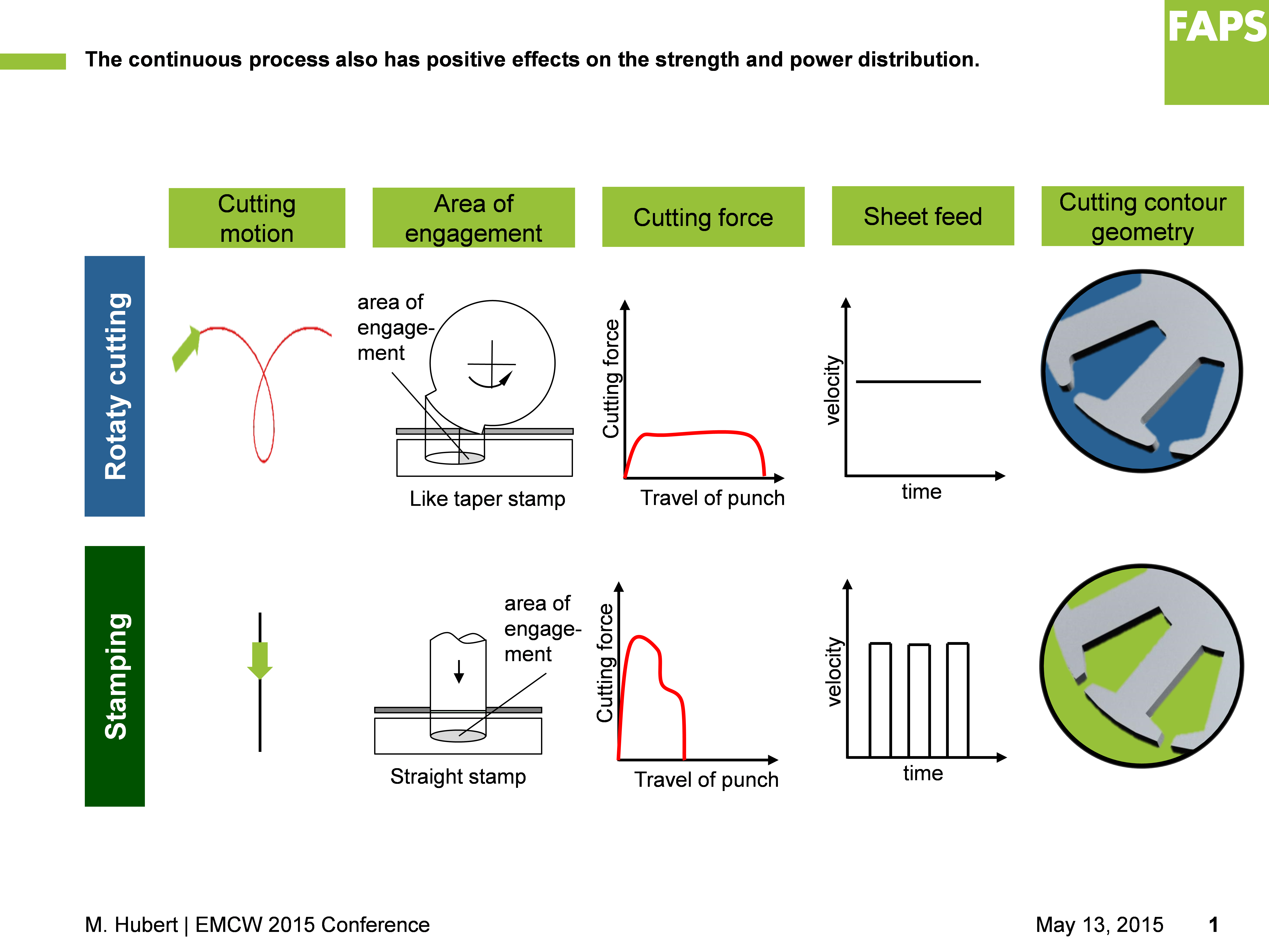 Figure 1 Comparison of Rotary Cutting with Stamping [3]
According to Figure 1 and [3], the conventional stamping process differs significantly from rotary cutting process through the following points:
- The cutting movement at stamping is linear with a permanent acceleration, deceleration and change of direction. In contrast, the rotary cutting cylinder moves continuous and describes a cycloid motion.
- During the rotary cutting process, the area of engagement is very small. At conventional stamping, the entire outline is cut at once.
- The maximum cutting force at stamping is very high and the travel of punch is very low.
- The speed of the sheet feed is constant during the rotary cutting process. Instead, the sheet feed speed is cyclical and clocked at stamping.
- Regarding the cutting contour geometry, laminations show sharp edged corners instead of a curved outline.
2. Comprehensive Analysis of the Rotary Cutting Method using Toroidal Core Tests
For a methodical examination of the cutting process, a suitable geometry is necessary. This is secured by toroidal core tests. With this simple geometry, the process behavior can be investigated during the separation process. Especially, cutting parameters, process stability and wear behavior can be evaluated. Thereby, it is possible to focus the tests on the cutting process without additional influences by complex contour elements, such as small radii. Secondly, it is possible to determine important characteristic values like power losses or magnetic and electric properties. In addition, an assessment of the sheet geometry is possible. Thus, process influences on the geometry can be investigated. To enable this, the toroidal core tests are comprehensively analyzed according to DIN IEC 60404-6. [4]
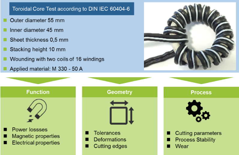 Figure 2 Toroidal core test per DIN 60404-6
The toroidal test specimens’ inner diameter Di is 45 mm and outer diameter Do is 55 mm. The lamination stack length lstack is 10 mm consisting of 20 single toroidal laminations with sheet thickness s = 0,5 mm. The single laminations are stacked without additional insulation layers between the laminations and wrapped with tape to a toroidal core. Finally, for investigation of electrical and magnetic properties, the toroidal core is wound with two coils of 16 windings each. [4]
Table 1 provides an overview of the manufacturers specific mechanical and magnetic properties for the applied material M 330 – 50 A. [4]
Table 1 Material Card for M 330 – 50 A
3. Machine Setup and Process Description for Rotary Cutting of Toroidal laminations
3.1. Machine and Tooling Setup
The prototype rotary cutting machine for toroidal laminations consists of four main components: Cutting unit, electric drive, control and decoiler. The drive unit is an SIEMENS asynchronous servomotor of type “SIMOTICS M-1PH8”. With a higher-level control, important motor parameters such as number of revolutions or torque can be set, controlled and monitored. [4]
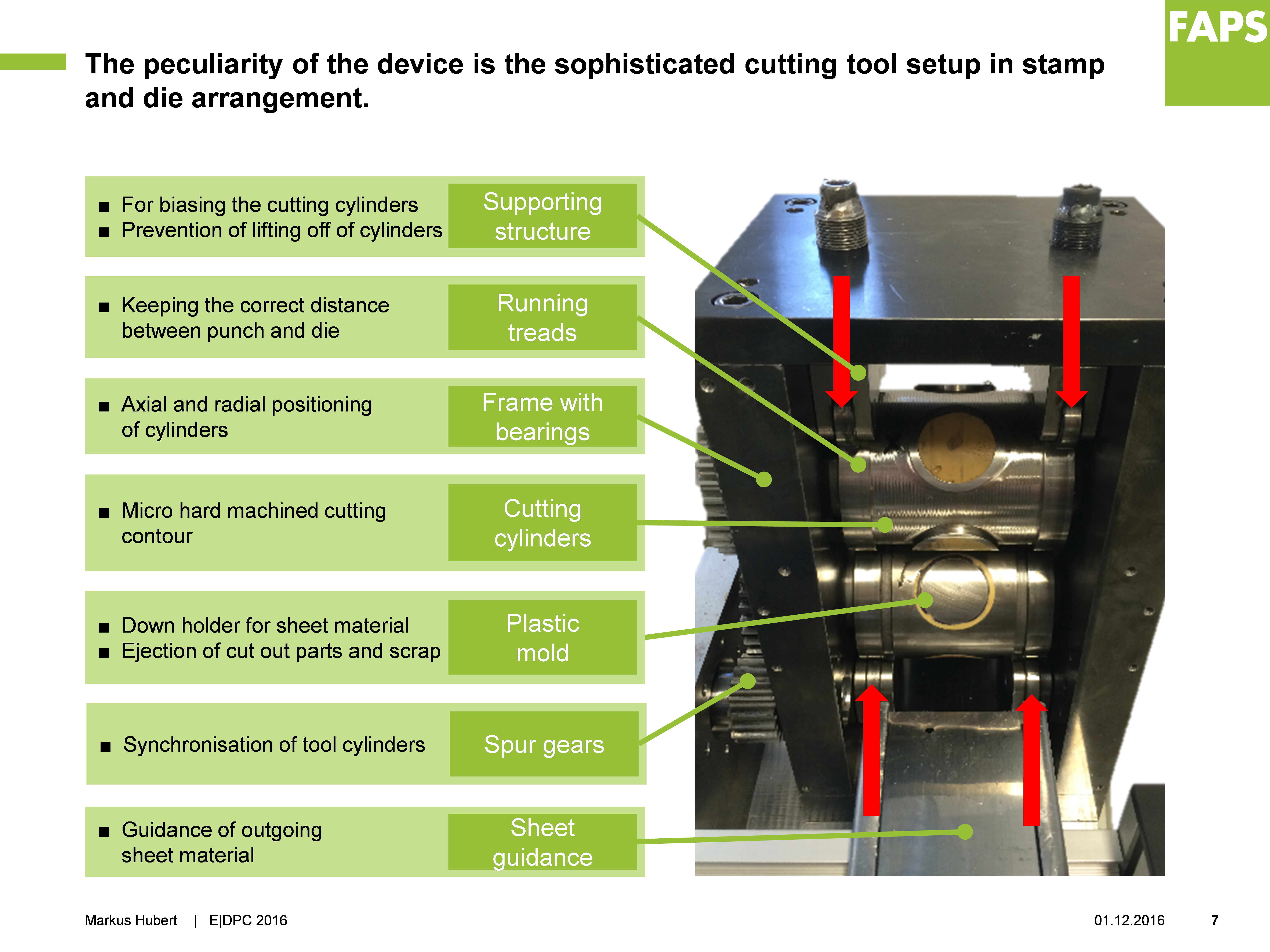 Figure 3 Prototype Rotary Cutting Device for Toroidal Core Samples [4]
The cutting unit itself essentially consists of five components: Tool set, gear box, pressure rollers, bearing unit and housing. The housing consists of four plates which are detachably connected by screws and pins. Thus, the cutting cylinders can be changed or subsequently adjusted. Two pressure rollers, which press against the running treads, relate to the housing to transfer the preload force on the cutting cylinders. Therefore, the cutting cylinder immerses in the material without lifting. [4]
The bearing unit is in the side walls of the housing. One side consists of two double-row angular contact ball bearings to absorb radial as well as axial forces. On the other side two cylindrical roller bearings are mounted as floating bearings. [4]
Moreover, at the drive side of the tool set, the spur gear is located. To ensure a synchronous and opposite rotation two gears of the same size are mounted on the shaft ends of the cylinders. To ensure the required dimensional accuracy and perfect cutting edges, one gear is being secured by a clamping sleeve in order to align both tool cylinders in radial direction. The pinion transmits the torque from the drive shaft to the spur gears. [4]
The cutting cylinders are core components of the rotary cutting machine for electrical steel. The tool set is arranged on top of each other. For rotary cutting processes in general, three tooling concepts are possible: wedge-action cutting, resilient cutting and stamp-die-cutting. However, for rotary cutting of electrical steel, only stamp-die-cutting is viable. [2, 4]
With this tooling concept, one cylinder acts as stamp and the other cylinder as die. For simple stamped holes with low accuracy requirements, the stamp may immerse into the die. For electrical steel processing with complex contour geometries and complete outlines, the stamp does not immerse into the die. Instead, the cutting unit must be designed in a way, that the stamp is located on the outer diameter of the die, the so called “zero to zero cutting” [5]. As a result, the lamination is cut by the stamp without immersion. Thus, a small die clearance is sufficient. To obtain reproducible cutting results, all process parameters have to harmonize with each other. [4]
In the conducted experiment, the geometry of the stamp is given by the toroidal geometry. The die has the corresponding negative form. In pre-trials the die clearance of 0.03 mm was determined as optimum for different sheet thicknesses. Thus, the outer diameter of the die DoD is manufactured 0.06 mm larger and the inner diameter DiD is manufactured 0.06 mm smaller compared to the stamp. The circumference of each cylinder is equipped with four cavities in total. The cutting circle diameter dc of the stamp cylinder as well as of the die cylinder is 108 mm. [4]
All cavities of the stamp and the die cylinders´ are filled with an elastic polyurethane casting compound with hardness of 90 Shore A. During the cutting process, the plastic performs as sheet downholder stamp-side and counterholder die-side. Moreover, the plastic ejects the lamination from the cutting area. This is necessary as otherwise the sheet remains stuck in the cavities after cutting. [5]
Since the sheet does not automatically exit the stamp completely after cutting, an external tensile force must act in sheet feed direction. Consequently, the sheet leaves the machining zone completely without jamming up. [4]
3.2. Description of the Rotary Cutting Process
The rotary cutting process is divided into 4 phases (according Figure 4). Following, the rotary cutting phases are described for stamp-die-cutting with closed cutting outline. [4, 6]
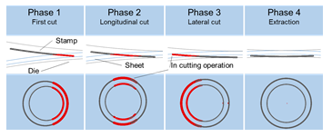 Figure 4 Four phases of rotary cutting referring to [6]
When the front edge of the stamp touches the sheet surface, the 1st phase of the cutting process starts. By further rotation, the cutting force is constantly increasing by forming the first crack until the entire sheet thickness is severed. [4, 6]
The cylinders continue to rotate, whereby the lateral cutting edges of the stamp cuts in the 2nd phase. The force level remains almost constant. [4, 6]
During phase 3, the back cutting edge impinges on the sheet metal and completes the cut. When the sheet is completely divided, the force level decreases abruptly. [4, 6]
After the rotary cutting process, the cutting sheet is pressed out of the die in the 4th phase. [4, 6]
For the description of the rotary cutting process, many different parameters are given. A decisively parameter is the angle of impact α, which defines starting- and endpoint of the line of action [7]. The angle of impact α depends on the circle diameter d, the vertical center distance a and the sheet thickness s and is derived from law of cosines. For good cutting results, the angle α should be very small. Thus, the length of line in action ls and length of the contour in action lc are getting small. [4]
According to [3], the angle of impact for equal diameters is defined by (1).
In contrast to the angle of impact α, the force progression during cutting is difficult to determine. By means of a calculating software, the length of contour in action lc for each contour can be calculated. This parameter behaves similarly to the force progression and can be used as a reference value. For the toroidal core test, the following diagram results (according Figure 5): [4, 8]With a sheet thickness s of 0.5 mm and a cutting circle diameter d of 108 mm, the angle of impact α is located at 5.5°. [4]
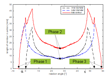 Figure 5 Length of contour in action per angle [8]
The total contour (red line) is explained as the summed curve of inner and outer diameter (black and blue line). [4]
A further parameter is the immersion depth of the stamp into the sheet ∆y. This value is varying during the cutting process and depends on the circle diameter d, the sheet thickness s, the angle of impact α and the entry angle β. According to [3], the immersion depth ∆y is: [4]
During the cutting process several velocities arise at the rotary cutting machine. The most important parameter is the circumferential speed vc, which results from the circumference d·π and the number of revolutions n.[4]with:
Since the speed of the lower sheet surface is faster than the upper one, there is a sheet speed difference ∆vsheet [4]. Table 2 gives an overview of applied process parameters.By means of (4), the resulting speed in x- and y-direction can be calculated. All equations for the different speed components can be found in [3]. [4]
Table 2 Applied Parameters of the test bench
3.3. Simulation model
Within the research project, a simulation model is created in ANSYS Workbench 15.0 and explicit finite element calculations are done by the LS-DYNA solver. Thereby, the tool cylinders are defined as not deformable rigid bodies and the electrical steel sheet as a flexible solid body. The simulation model is assumed as quasi static. [8]
The material model of the electrical steel is defined by Johnson and Cook. This approach is very popular in metal cutting process simulations [9]. The three elementary material behaviors included in the model are material hardening, strain rate effects and thermal softening [10]. However, in this FEM model strain rate effects and thermal softening are neglected. [8]
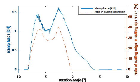 Figure 6 Simulated force-rotation path [8]
The CAD model of the geometry only includes important components. In addition, the cylinders are limited to 7° large shell elements. These simplifications reduce the required calculation time significantly. [8]
Figure 6 shows a comparison of the stamp force engaged cutting length over the rotation angel for a simplified geometry of a round stamp with a diameter of 5.00 mm and a steel strip thickness of 0.50 mm. At a rotation angle of -2.5°, the maximum stamp force of about 1.6 kN is reached. At this point, the entire cutting edge is in contact with the sheet. The pulling out of the sheet causes a negative stamp force. [8]
4. Results and Discussion of the Rotary Cutting Experiments
To analyze the influence of the cutting process, several electric sheet strips are cut with the test bench. The preload torque for all tests is 60 Nm and the sheet thickness is 0.5 mm. First, the process behavior is evaluated. Second, the geometry and the functionality of the laminations are analyzed. Micro sections of the different phases are made to investigate the cutting edges of the toroidal laminations. The contour of the geometry is analyzed with a multi-sensor coordinate measuring machine VideoCheck IP 400 HA from Werth. And third, the electrical and magnetic behavior of the toroidal core is evaluated on an electrical steel tester MPG 200 from Brockhaus Measurements. [4]
4.1. Characteristics of process behavior
The toroidal core samples are cut completely from the steel strip. However, the samples adhere at the inner contour due to slight wedging. Thus, the separation occurs manually. The toroidal samples are slightly deformed and bent in sheet feed direction, as high forces occur. Thus, the laminations must be arranged after cutting. A further reduction of the bending arises with an adjustment of the machine settings. Larger cylinders or an additional recoiler with a further tensile force decrease the deformations. Since the design of the test bench is very simple, the cutting speed is very low. However, a higher cutting speed improves the results significantly. The cutting results at a sheet thickness of 0.5 mm and 60 Nm preload torque is shown in Figure 7. [4]
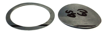 Figure 7 Rotary cut toroidal laminations
A high process stability is mandatory for a high cutting quality at the rotary cutting process. To fulfil perfect process settings, several important parameters must be optimized. A precise alignment of the tool set is essential to provide a perfect cutting clearance and avoid squeezing the sheet. Another important factor of the rotary cutting process is the setup of the correct preload torque. The cutting cylinders may not take-off, when the stamp immerses the sheet. However, deformation gets stronger with increasing preload torque. [4]
To implement the downholder and ejector function, the cavities of stamp and die are filled with plastics. During the cutting process, the plastic performs as a downholder and establishes a counterforce to avoid deformation. After cutting it also applies the force to eject the lamination from the die. In absence of the plastics component, the sheet strongly deforms and is pulled into the die by tensile stresses after the cutting process. Consequently, strong deformation occurs at the cutting edges and in the lamination. [4]
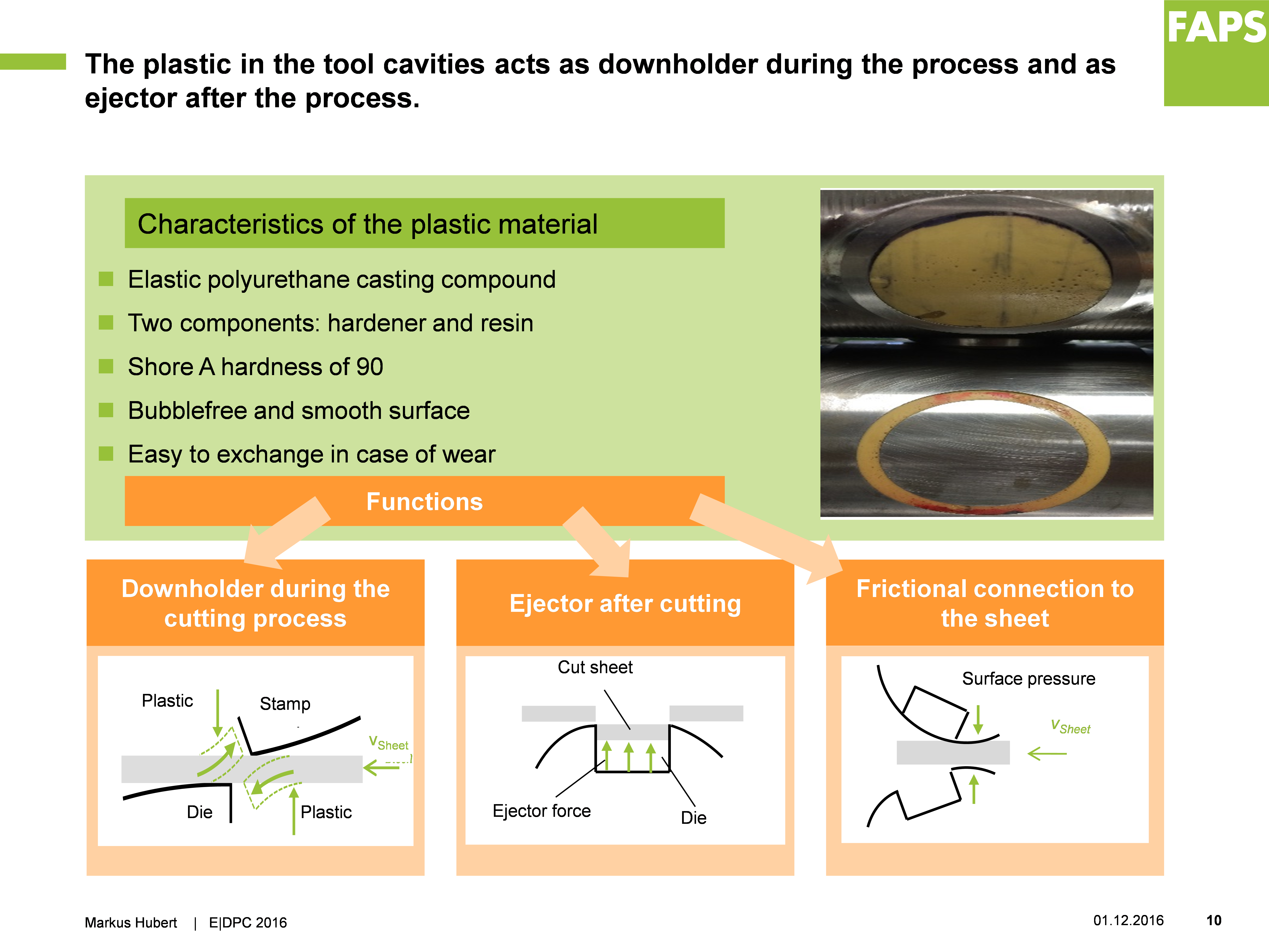 Figure 8 Characteristics of the plastics matrix
In contrast to the rotary cutting process, the process stability of the conventional stamping is very high. This is due to long experiences in this traditional process. The cutting speed and the application rate is thereby very high. In addition, the flat tooling structure and further downholder generate flat blanks without any deformations. However, the high cutting forces of up to 2,500 kN are very inefficient. To reach the required accuracy, massive and rigid stamps are necessary, which cause high investment costs. The High production costs of tools and large conversion effort are the main challenges of stamping with a wide variety. [1]
4.2. Toroidal lamination geometric properties
For the geometry measurement of the toroidal laminations, the Werth VideoCheck IP is used. In Figure 9 the results of the toroidal core sample are shown with a tolerance of ± 0.05 mm. The areas marked in red represent an exceedance of the tolerance limit. Consequently, the green areas are inside the tolerance. A total of approximately 25% of the measurement points are within the tolerances of ± 0.05 mm. [4]
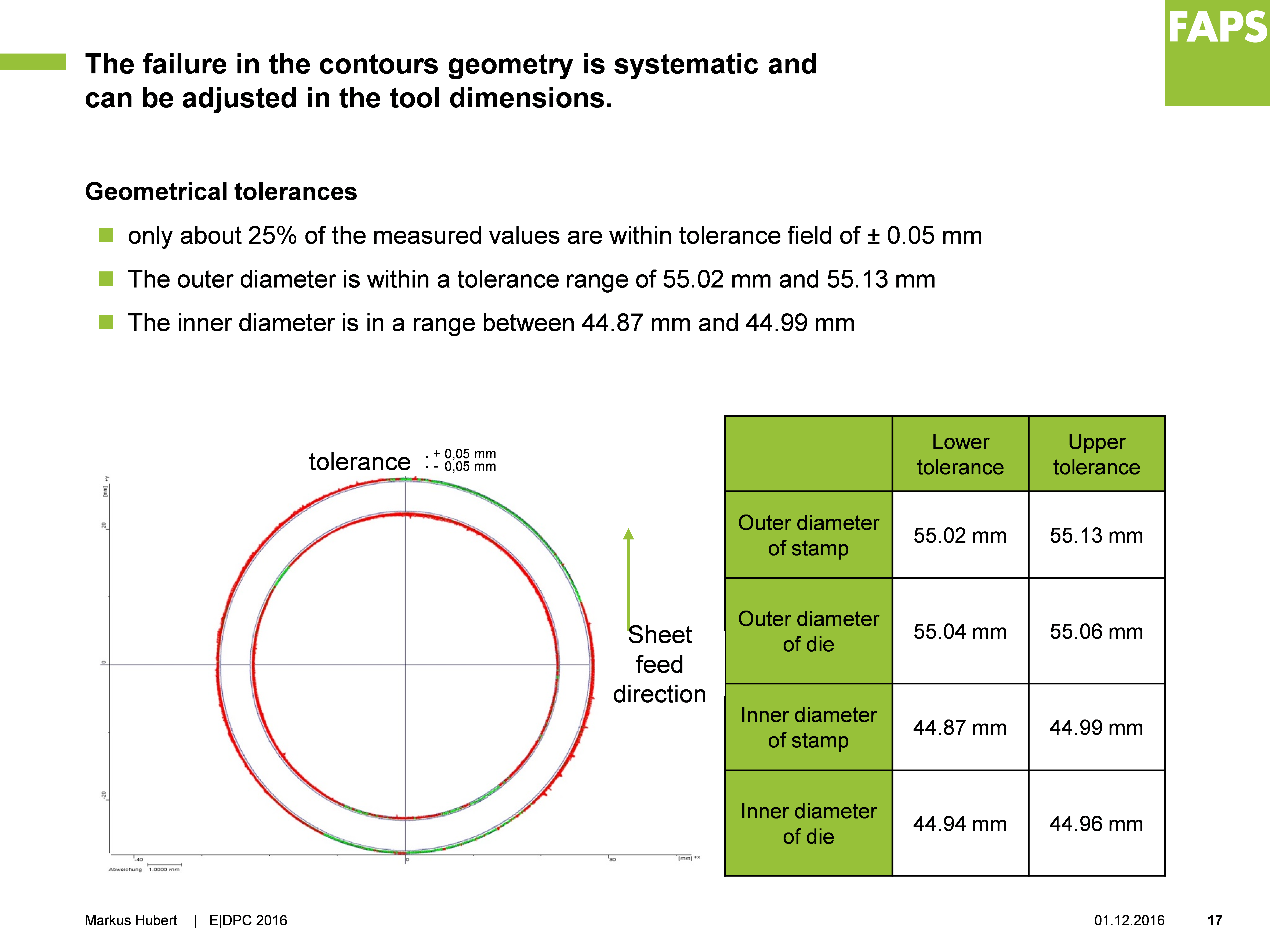 Figure 9 Matching of actual and target toroidal contour
In the tolerance field of ± 0.05 mm, the measured contour of the inner diameter exceeds the lower tolerance limit and the measured contour of the outer diameter exceeds the upper tolerance limit. Further investigations on the outer diameter show, that all measured values for the outer diameter are between 55.02 mm and 55.13 mm. Therefore, the average outer diameter is 55.07 mm. At the inner diameter, the measured values are between 44.87 mm and 44.99 mm. The average inner diameter is 44.93 mm. [4]
When considering the results of measurement, two factors are particularly of relevance. First, a general deviation of the dimensions of inner and outer diameter. The outer diameter is at most of the measuring points larger and the inner diameter smaller than the target contour. This is due to the tolerances of the tools. The cutting clearance of 0.03 mm is applied die sided and tolerated from 55.04 mm to 55.06 mm on the outer diameter and from 44.96 mm to 44.94 mm on the inner diameter. As a consequence, for future design of tools, the die is to be tolerated with the nominal dimension and the stamp must be adapted for the cutting clearance. The second deviation is at the inner diameter. It deviates most from the nominal dimension right of the inlet. The corresponding range on the outer diameter is close to the target dimension. This context implies a slight general deformation of the sheet. This can be explained by bumpy placement of the toroidal laminations on the measuring table and as a result the inner and outer diameter appear smaller in evaluation. [4]
An advantage of stamping is the very high accuracy of the manufactured parts. Stamped laminations do not have any deviations or failures and reach tolerance classes up to IT6/7. The separated laminations also can be stacked or packaged in the stamping machine. However, stamping of very thin sheets (lower than 0.30 mm) is process-related very difficult. Furthermore, the production of thin sheets with a high accuracy is cost-intensive and the processing speed must be reduced. This is due to the exact positioning of the thin and limp sheets in the stamping tools. [1]
For investigation of the cutting edge and burr, micro sections of the rotary cut laminations are made. The shown sectors in Figure 10 are the different phases of the rotary cutting process. The top of each micro section shows the stamp side and the bottom the die side of the lamination. [4]
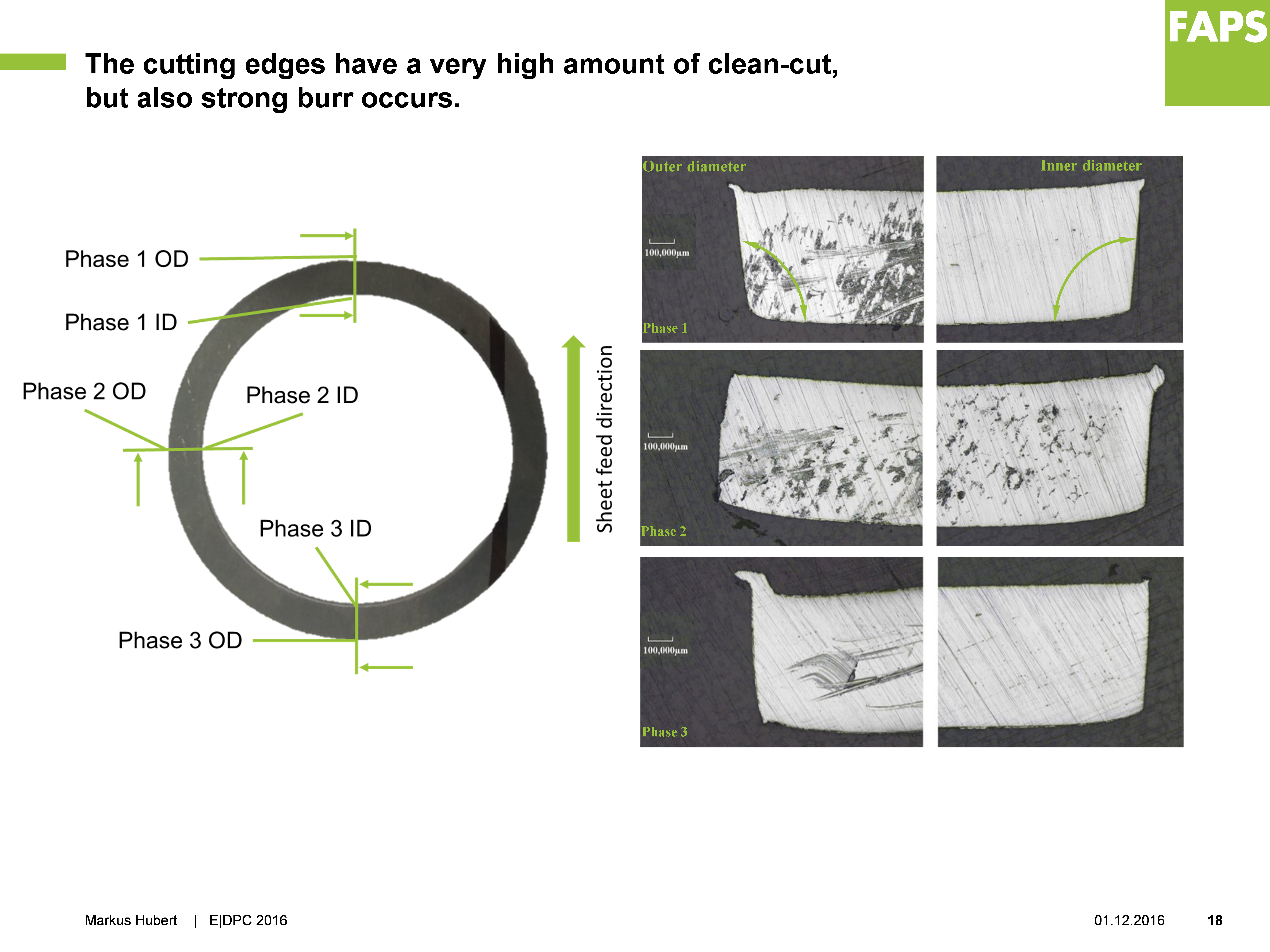 Figure 10 Microsections of rotary cut toroidal lamninations
The cutting edges of phase 1 show a typical cutting surface of shear cutting with the following areas. Top sided, there is a fractured face with burr. In the middle of the cutting edge, a smooth cutting zone is visible. Lastly, dented edges are at the bottom. Resulting from the inaccurate orientation of the cylinders, the largest burr formation is at the outer diameter of phase 3. In contrast, the inner diameter of phase 3 is nearly burr-free. Consequently, the cutting clearances of inner and outer diameter are different. The test results show that the cutting clearance of the outer diameter is too small. Moreover, it is possible that the stamp pushes against the sheet. As the cutting clearance is perfect at the inner diameter, no burr appears. The angels of all cutting edges are between 94.0° and 98.0°. These deviations arise from tilting between stamp and die. Due to the rotary movement, the angle changes constantly during cutting process. [4]
4.3. Toroidal lamination magnetic and electric properties
The electric and magnetic properties of the rotary cut toroidal cores are determined with an Brockhaus Measurements electrical steel tester. The Toroidal cores specimens consist of 20 single laminations, wrapped in tape and wound with two coils of 16 windings. [4]
To determine the hysteresis loop and the hysteresis- and eddy-current losses, measurements are carried out at polarizations of up to 1.50 T and frequencies between 50 Hz and 200 Hz. [4]
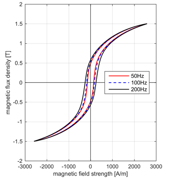 Figure 11 Hysteresis loops for rotrary cut electrical steel at 50, 100 and 200 Hz
At a frequency of 50 Hz and a field strength of 2,500 A/m, the toroidal core shows a polarization of 1.48 T. However, the hysteresis curve is very flat and does not have the desired Z-shape. Thus, the remanence is not very high after magnetizing the toroidal core. In a magnetization of 200 Hz, the remanence of the toroidal core is 0.57 T. With optimal magnetic properties, this would be as close as possible to the applied polarization of 1.5 T. [4]
According to Table 1, the total losses of the starting material at a polarization of 1.50 T and a frequency of 50 Hz are 3.30 W/kg. Although hysteresis and eddy-current losses, which are influenced by unevenness, burr formation and air gaps between the individual sheets, are significantly higher in case of the rotary cut toroidal cores, the result is typical for electric steel laminations. Due to deformation during the cutting process, cold forming occurs in the metal sheets, what is negatively effecting electrical and magnetic properties. Figure 12 shows the hysteresis and eddy-current losses of the toroidal core at different frequencies. [4]
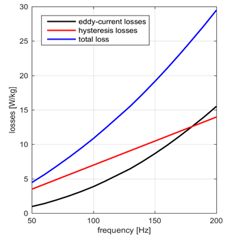 Figure 12 Hysteresis and eddy current losses of the toroidal core
The total of hysteresis and eddy current losses in the toroidal core at 50 Hz is 4.46 W/kg. This value is factor 1.35 greater than the starting value. After conventional stamping, the increasing of total losses is similar to this value. In order to achieve improvements in electrical and magnetic properties, deformation during rotary cutting has to be reduced by further development of the process. [4]
5. Conclusion
With the help of the rotary cut toroidal core samples, it has been shown that the process is generally suitable for the processing of electrical steel strip. However, the results also indicate that a great deal of development work still needs to be done. In particular, a detailed adjustment of the process parameters is necessary to achieve a stable level of high quality. To further intensify process understanding, a long-term experiment with a real application is recommended. Process stability, reproducibility and tool life can then be demonstrated.
6. Summary
This publication constitutes the state of research of rotary cutting of electrical steel strip using a toroidal core sample. Based on this analysis, a distinct statement on the technically feasible parameters is achieved and it allows a comparison with applied industrial processes.
Conflict of Interest
The authors declare no conflict of interest.
Acknowledgment
This research activity was kindly supported by the research project “Entwicklung eines Rotationsschneidverfahrens fuer duenne Elektroblechfolien (E|RoCut)” funded by the Central Innovation Programme for SMEs (ZIM) of the Federal Ministry for Economic Affairs and Energy (BMWi) in Germany.
- J. Franke et al., “Laserschneiden in der Elektroblechfertigung: Flexible und produktive Produktion dünner Elektrobleche für elektrische Traktionsmotoren in Elektrofahrzeugen,” ZWF, vol. 107, no. 9, pp. 642–646, 2012.
- M. Hubert, J. Franke, and J. Hackert, “Continuous rotational cutting of laminations for electric drives: Cutting process and tool setups for rotational cutting of laminations,” in 2014 4th International Electric Drives Production Conference (E|DPC): Proceedings: Sept. 30, 2014 – Oct. 1, 2014, Nuremberg, Germany, Piscataway, NJ: IEEE, 2014, pp. 1–5.
- M. Hubert, H. Rosenow, J. Franke, and J. Hackert, “Rotary cutting as an alternative method in the processing of electrical steel strip: Geometric and kinematic determination of the process setup,” in 2015 5th International Electric Drives Production Conference (E|DPC): Proceedings: September 15th – 16th 2015, Nuremberg, Germany, [Piscataway, New Jersey]: IEEE, 2015, pp. 1–5.
- M. Hubert et al., “Analysis of the Rotary Cutting Process of Electrical Steel on Basis of a Toroidal Core Test,” in 2016 6th International Electric Drives Production Conference (EDPC): IEEE, 2016, pp. 230–236.
- J. Hackert, “Anlage zum Rotationsschneiden von Elektroblechen,” DE 10 2013 018 995, Germany DE 10 2013 018 995 B4.
- M. Schweitzer, “Prozessspezifische Merkmale des Rotationsschneidens,” PhD Thesis, Lehrstuhl für Umformtechnik und Gießereiwesen, Technische Universität München, München, 2001.
- G. Blumauer and E. Koehler, “Beitrag zur Untersuchung des Rotationsstanzens von Karton,” PhD Thesis, Fakultaet für Maschineningenieurwesen, Technische Hochschule Karl-Marx-Stadt, Karl-Marx-Stadt, 1974.
- M. Hubert et al., “Explicit Finite Element Analysis for Rotary Cutting of Electrical Steel Sheet,” in InAES 2016 – The 6th International Annual Engineering Seminar: Conference Proceedings; August 1st – 3rd, 2016, Yogyakarta, Indonesia: IEEE, 2016.
- L. Bohdal and L. Kukielka, “The effect of selected material parameters on the stress and strain states in the process of cutting a sheet plate with circular cutters,” in vol. 4, Task Quarterley: Scientific Bulletin of Academic Computer Centre in Gdańsk, Politechnika Gdańska, Ed., 2006, pp. 391–400.
- G. R. Johnson and W. H. Cook, “A constitutive model and data for metals subjected to large strains, high strain rates and high temperatures,” Proceedings of the 7th International symposium on ballistics, pp. 541–547, 1983.